PONTIAC FIERO 1988 Service Repair Manual
Manufacturer: PONTIAC, Model Year: 1988, Model line: FIERO, Model: PONTIAC FIERO 1988Pages: 1825, PDF Size: 99.44 MB
Page 1701 of 1825
2H-4 STATIONARY GLASS - F STYLE
7. Watertest car at once using soft spray. Use warm
or hot water if available. Do not direct hard
stream of water at fresh adhesive material. If any
leaks are found, paddle in extra adhesive at leak
point using a small disposable brush or
flat-bladed tool. Water applied on top of urethane
adhesive, either during watertest or as a separate
operation, will speed up the cure of the urethane.
8. Install windshield reveal molding.
9. Install
all other previously removed parts and
clean up.
10. On windshield installations, car must remain at
normal room temperature for six hours to
complete proper cure of adhesive.
Extended Method
It will be necessary to use extended installation
method if prior service installation was made with
butyl tape or if urethane material remaining in window
opening after window removal is damaged, or must be
removed to permit refinishing of window opening.
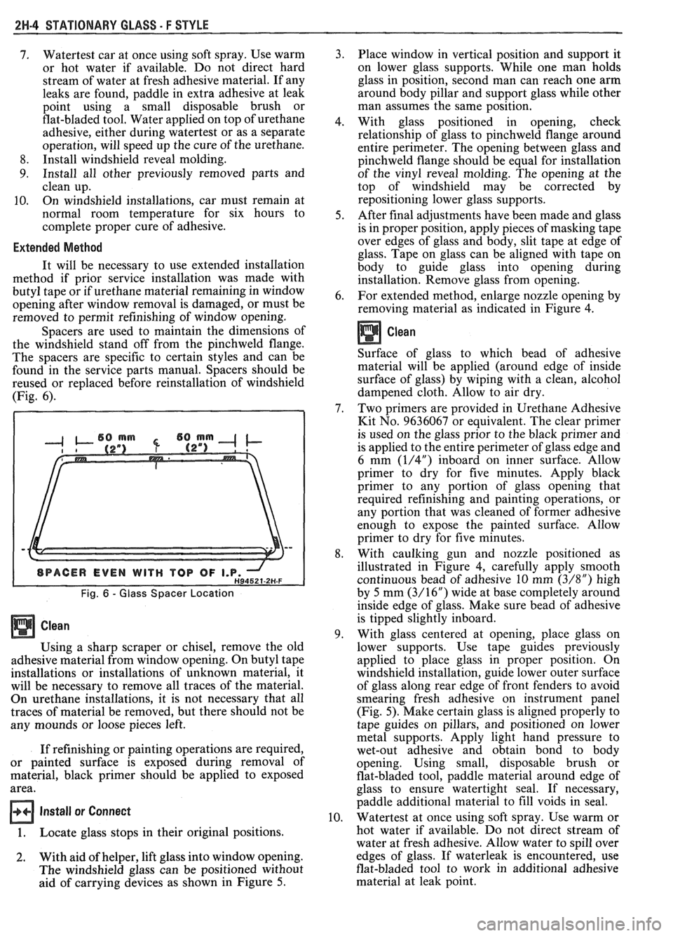
Spacers are used to maintain the dimensions of
the windshield stand off from the pinchweld flange.
The spacers are specific to certain styles and can be
found in the service parts manual. Spacers should be
reused or replaced before reinstallation of windshield
(Fig. 6).
Fig. 6 - Glass Spacer Location
Using a sharp scraper or chisel, remove the old
adhesive material from window opening. On butyl tape
installations or installations of unknown material, it
will be necessary to remove all traces of the material.
On urethane installations, it is not necessary that all
traces of material be removed, but there should not be
any mounds or loose pieces left.
If refinishing or painting operations are required,
or painted surface is exposed during removal of
material, black primer should be applied to exposed
area.
Install or Connect
1. Locate glass stops in their original positions.
2. With aid of helper, lift glass into window opening.
The windshield glass can be positioned without
aid of carrying devices as shown in Figure 5. Place window
in vertical position and support it
on lower glass supports. While one man holds
glass in position, second man can reach one arm
around body pillar and support glass while other
man assumes the same position.
With glass positioned in opening, check
relationship of glass to pinchweld flange around
entire perimeter. The opening between glass and
pinchweld flange should be equal for installation
of the vinyl reveal molding. The opening at the
top of windshield may be corrected by
repositioning lower glass supports.
After final adjustments have been made and glass
is in proper position, apply pieces of masking tape
over edges of glass and body, slit tape at edge of
glass. Tape on glass can be aligned with tape on
body to guide glass into opening during
installation. Remove glass from opening.
For extended method, enlarge nozzle opening by
removing material as indicated in Figure
4.
Clean
Surface of glass to which bead of adhesive
material will be applied (around edge of inside
surface of glass) by wiping with a clean, alcohol
dampened cloth. Allow to air dry.
Two primers are provided in Urethane Adhesive
Kit No. 9636067 or equivalent. The clear primer
is used on the glass prior to the black primer and
is applied to the entire perimeter of glass edge and
6 mm
(1/4") inboard on inner surface. Allow
primer to dry for five minutes. Apply black
primer to any portion of glass opening that
required refinishing and painting operations, or
any portion that was cleaned of former adhesive
enough to expose the painted surface. Allow
primer to dry for five minutes.
With caulking gun and nozzle positioned as
illustrated in Figure 4, carefully apply smooth
continuous bead of adhesive 10 mm
(3/8") high
by 5 mm
(3/16") wide at base completely around
inside edge of glass. Make sure bead of adhesive
is tipped slightly inboard.
With glass centered at opening, place glass on
lower supports. Use tape guides previously
applied to place glass in proper position. On
windshield installation, guide lower outer surface
of glass along rear edge of front fenders to avoid
smearing fresh adhesive on instrument panel
(Fig. 5). Make certain glass is aligned properly to
tape guides on pillars, and positioned on lower
metal supports. Apply light hand pressure to
wet-out adhesive and obtain bond to body
opening. Using small, disposable brush or
flat-bladed tool, paddle material around edge of
glass to ensure watertight seal. If necessary,
paddle additional material to fill voids in seal.
Watertest at once using soft spray. Use warm or
hot water if available. Do not direct stream of
water at fresh adhesive. Allow water to spill over
edges of glass. If waterleak is encountered, use
flat-bladed tool to work in additional adhesive
material at leak point.
Page 1702 of 1825
STATIONARY GLASS - F STYLE 2H-5
1 1.
Install windshield reveal molding.
12. Install all other previously removed parts and
clean up.
13. On windshield installations, car must remain at
normal room temperature for six hours to
complete proper cure of adhesive material.
WATERLEAK CORRECTION
Urethane glass installation waterleaks can be
corrected without removing and reinstalling glass
where accessible. This method applies only with use of
adhesive furnished in kit no. 9636067 or equivalent.
1. Remove reveal moldings in area of leak. In some
cases, it may become necessary to remove garnish
moldings or finishing lace to locate source of leak.
2. Mark location of
leak(s). Carefully push outward
on glass in area of leak to determine extent of
leak. This operation should be performed while
water is being applied to leak area. Mark extent
of leak area.
@ Clean
From outside body, clean any dirt or foreign
material from leak area with water; then dry area
with air hose.
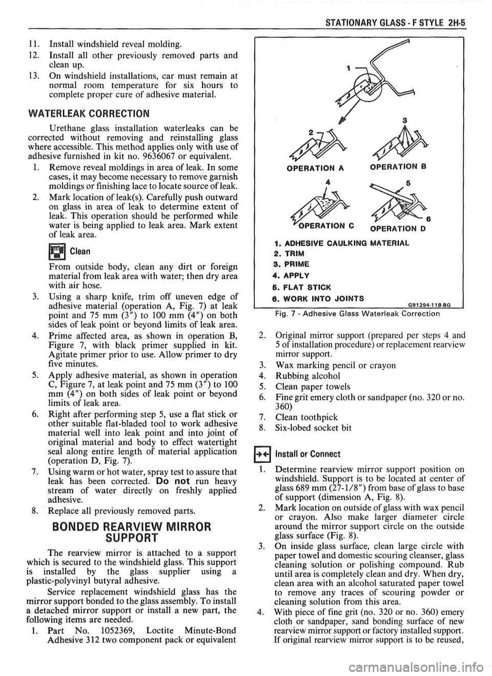
3. Using a sharp knife, trim off uneven edge of
adhesive material (operation A, Fig. 7) at leak
point and 75 mm
(3") to 100 mm (4") on both
sides of leak point or beyond limits of leak area.
4. Prime affected area, as-shown in operation B,
Figure 7, with black primer supplied in kit.
Agitate primer prior to use. Allow primer to dry
five minutes.
5. Apply adhesive material, as shown in operation
C, Figure 7, at leak point and 75 mm (3") to 100
mm (4") on both sides of leak point or beyond
limits of leak area.
6. Right after performing step 5, use a flat stick or
other suitable flat-bladed tool to work adhesive
material well into leak point and into joint of
original material and body to effect watertight
seal along entire length of material application
(operation D, Fig. 7).
7. Using warm or hot water, spray test to assure that
leak has been corrected.
Do not run heavy
stream of water directly on freshly applied
adhesive.
8. Replace all previously removed parts.
BONDED REARVIEW MIRROR
SUPPORT
The rearview mirror is attached to a support
which is secured to the windshield glass. This support
is installed by the glass supplier using a
plastic-polyvinyl butyral adhesive.
Service replacement windshield glass has the
mirror support bonded to the glass assembly. To install
a detached mirror support or install a new part, the
following items are needed.
1. Part No. 1052369, Loctite Minute-Bond
Adhesive 3 12 two component pack or equivalent
OPERATION A OPERATION B
OPERATION D
1. ADHESIVE CAULKING MATERIAL
2. TRIM
3. PRIME
4. APPLY
6. FLAT STICK
6. WORK INTO JOINTS 691294.1 18-BG
Fig. 7 - Adhesive Glass Waterleak Correction
2. Original mirror support (prepared per steps 4 and
5 of installation procedure) or replacement rearview
mirror support.
3. Wax marking pencil or crayon
4. Rubbing alcohol
5. Clean paper towels
6. Fine grit emery cloth or sandpaper (no. 320 or no.
3 60)
7. Clean toothpick
8. Six-lobed socket bit
Install or Connect
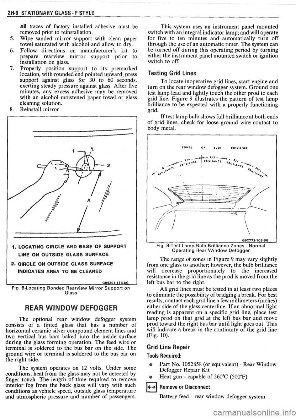
1. Determine rearview mirror support position on
windshield. Support is to be located at center of
glass 689 mm
(27-1/8") from base of glass to base
of support (dimension A, Fig.
8).
2. Mark location on outside of glass with wax pencil
or crayon. Also make larger diameter circle
around the mirror support circle on the outside
glass surface (Fig. 8).
3. On
inside glass surface, clean large circle with
paper towel and domestic scouring cleanser, glass
cleaning solution or polishing compound. Rub
until area is completely clean and dry. When dry,
clean area with an alcohol saturated paper towel
to remove any traces of scouring powder or
cleaning solution from this area.
4. With piece of fine grit (no. 320 or no. 360) emery
cloth or sandpaper, sand bonding surface of new
rearview mirror support or factory installed support.
If original
rearview mirror support is to be reused,
Page 1703 of 1825
2H-6 STATIONARY GLASS - F STYLE
all traces of factory installed adhesive must be
removed prior to reinstallation.
5. Wipe sanded mirror support with clean paper
towel saturated with alcohol and allow to dry.
6. Follow directions on manufacturer's kit to
prepare
rearview mirror support prior to
installation on glass.
7. Properly position support to its premarked
location, with rounded end pointed upward; press
support against glass for 30 to 60 seconds,
exerting steady pressure against glass. After five
minutes, any excess adhesive may be removed
with an alcohol moistened paper towel or glass
cleaning solution.
8. Reinstall mirror
4. LOCATING CIRCLE AND BASE OF SUPPORT
LINE ON OUTSIDE GLASS SURFACE
2. CIRCLE ON OUTSIDE GLASS SURFACE
INDICATES AREA TO BE CLEANED
G94301-11 B.BG
Fig. 8-Locating Bonded earv view Mirror Support on
Glass
REAR WlMBOW DEFOGGER
The optional rear window defogger system
consists of a tinted glass that has a number of
horizontal ceramic silver compound element lines and
two vertical bus bars baked into the inside surface
during the glass forming operation. The feed wire or
terminal is soldered to the bus bar on the side. The
ground wire or terminal is soldered to the bus bar on
the right side.
The system operates on 12 volts. Under some
conditions, heat from the glass may not be detected by
finger touch. The length of time required to remove
interior fog from the back glass will vary with such
conditions as vehicle speed, outside glass temperature
and atmospheric pressure and number of passengers. This
system uses an instrument panel mounted
switch with an integral indicator lamp; and will operate
for five to ten minutes and automatically turn off
through the use of an automatic timer. The system can
be turned off during this operating period by turning
either the instrument panel mounted switch or ignition
switch to off.
Testing Grid Lines
To locate inoperative grid lines, start engine and
turn on the rear window defogger system. Ground one
test lamp lead and lightly touch the other prod to each
grid line. Figure
9 illustrates the pattern of test lamp
brilliance to be expected with a properly functioning
grid.
If test lamp bulb shows full brilliance at both ends
of grid lines, check for loose ground wire contact to
body metal.
Fig. 9-Test Lamp Bulb Brilliance Zones - Normal
Operating Rear Window Defogger
The range of zones in Figure 9 may vary slightly
from one glass to another; however, the bulb brilliance
will decrease proportionately to the increased
resistance in the grid line as the prod is moved from the
left bus bar to the right.
All grid lines must be tested in at least two places
to eliminate the possibility of bridging a break. For best
results, contact each grid line a few millimeters (inches)
either side of the glass centerline. If an abnormal light
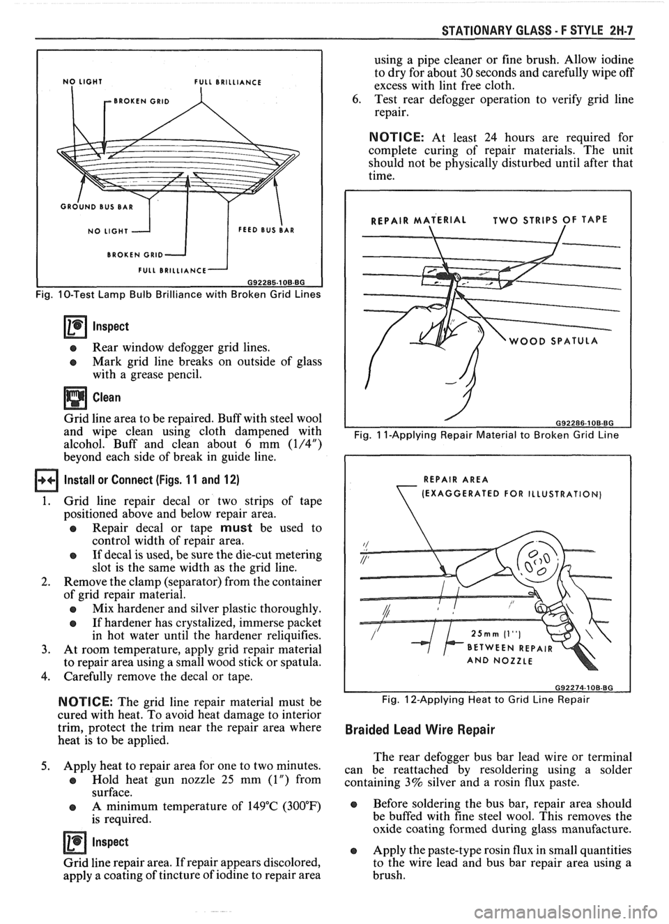
reading is apparent on a specific grid line, place test
lamp prod on that grid at the left bus bar and move
prod toward the right bus bar until light goes out. This
will indicate a break in the continuity of the grid line
(Fig.
10).
Grid Line Repair
Tools Required:
o Part No. 1052858 (or equivalent) - Rear Window
Defogger Repair Kit
e Heat gun - capable of 260°C (500°F)
Remove or Disconnect
Battery 'feed - rear window defogger system
Page 1704 of 1825
STATIONARY GLASS - F STYLE 2W.7
L BRILLIANCE
BROKEN
GRlD
BROKEN GRlD
Fig. 10-Test Lamp Bulb Brilliance with Broken Grid Lines
Inspect
e Rear window defogger grid lines.
e Mark grid line breaks on outside of glass
with a grease pencil.
Clean
Grid line area to be repaired. Buff with steel wool
and wipe clean using cloth dampened with
alcohol. Buff and clean about
6 mm (1/4")
beyond each side of break in guide line.
Install or Connect (Figs. 1 1 and 12)
1. Grid
line repair decal or two strips of tape
positioned above and below repair area.
a Repair decal or tape must be used to
control width of repair area.
e If decal is used, be sure the die-cut metering
slot is the same width as the grid line.
2. Remove the clamp (separator) from the container
of grid repair material.
a Mix hardener and silver plastic thoroughly.
e If hardener has crystalized, immerse packet
in hot water until the hardener reliquifies.
3. At room temperature, apply grid repair material
to repair area using a small wood stick or spatula.
4. Carefully remove the decal or tape.
NOTICE: The grid line repair material must be
cured with heat. To avoid heat damage to interior
trim, protect the trim near the repair area where
heat is to be applied.
5. Apply heat to repair area for one to two minutes.
a Hold heat gun nozzle 25 mm (1") from
surface.
e A minimum temperature of 149°C (300°F)
is required.
Inspect
Grid line repair area. If repair appears discolored,
apply a coating of tincture of iodine to repair area using
a pipe cleaner or fine brush. Allow iodine
to dry for about
30 seconds and carefully wipe off
excess with lint free cloth.
6. Test rear defogger operation to verify grid line
repair.
NOTICE: At least 24 hours are required for
complete curing of repair materials. The unit
should not be physically disturbed until after that
time.
WOOD SPATUL
Fig. 1 I-Applying Repair Material to Broken Grid Line
REPAIR AREA
(EXAGGERATED
FOR ILLUSTRATION)
Fig. 12-Applying Heat to Grid Line Repair
Braided Lead Wire Repair
The rear defogger bus bar lead wire or terminal
can be reattached by resoldering using a solder
containing 3% silver and a rosin flux paste.
e Before soldering the bus bar, repair area should
be buffed with fine steel wool. This removes the
oxide coating formed during glass manufacture.
e Apply the paste-type rosin flux in small quantities
to the wire lead and bus bar repair area using a
brush.
Page 1705 of 1825
2H-8 STATIONARY GLASS - F STYLE
e The soldering iron tip should be coated with the
solder and only enough solder to ensure a
solder beforehand. Use only enough heat to melt complete repair.
e Do
not overheat the wire when resoldering it to
the bus bar.
Page 1706 of 1825
UNDERBODY-F STYLE 3H-1
SECTION 3H
UNDERBODY
CONTENTS
General Body Construction .......................................................................................................... 3H- 1
Alignment Checking ................................................................................................................ 3H- I
Floor Pan Insulators ...................... .. ........................................................................................ 3H- 1
Floor Carpets ................................................................................................................................. 3H-2
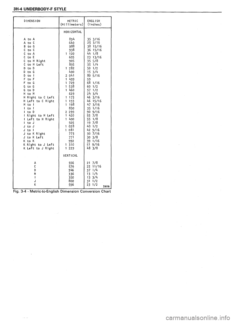
metric-to-English dimensional conversion data.
Dimensions to gage holes are measured to dead center
GENERAL BODY CONSTRUCTION of the holes and flush to adjacent surface metal unless
Information in this section pertains to unitized otherwise specified.
body construction which
incorporates integral front
and rear frame side rails. FLOOR PAN INSULATORS
Consideration must be given when checking
underbody dimensions. The engine front suspension
lower control arms are supported by a cross member.
The cross member, in turn, is bolted to the body at six
locations
-- three on each side of the engine front
compartment lower rails. Mounting provisions for the
front suspension system are shared by chassis
components (suspension lower control arms and cross
member) and body components (engine compartment
side panels). The suspension strut towers must be
dimensionally correct in relation to the remainder of
the underbody in order to maintain specified
suspension strut and
castedcamber angles.
Since the individual underbody components also
contribute directly to the overall strength of the body,
it is essential that proper welding techniques be
observed during service repair operations. The
underbody components should be properly sealed and
rustproofed whenever body repair operations destroy
or damage the original sealing and rustproofing. When
rustproofing critical underbody components, it is
essential that a good quality type of air dry primer be
used (such as corrosion resistant chromate or
equivalent material). It is not advisable to use
combination type primer-surfacers.
ALIGNMENT CHECKING
An accurate method of determining the
alignment of the underbody utilizes a measuring tram
gage. The tram gage set required to perform the
recommended measuring checks must include a
vertical pointer capable of reaching 914 mm (36").
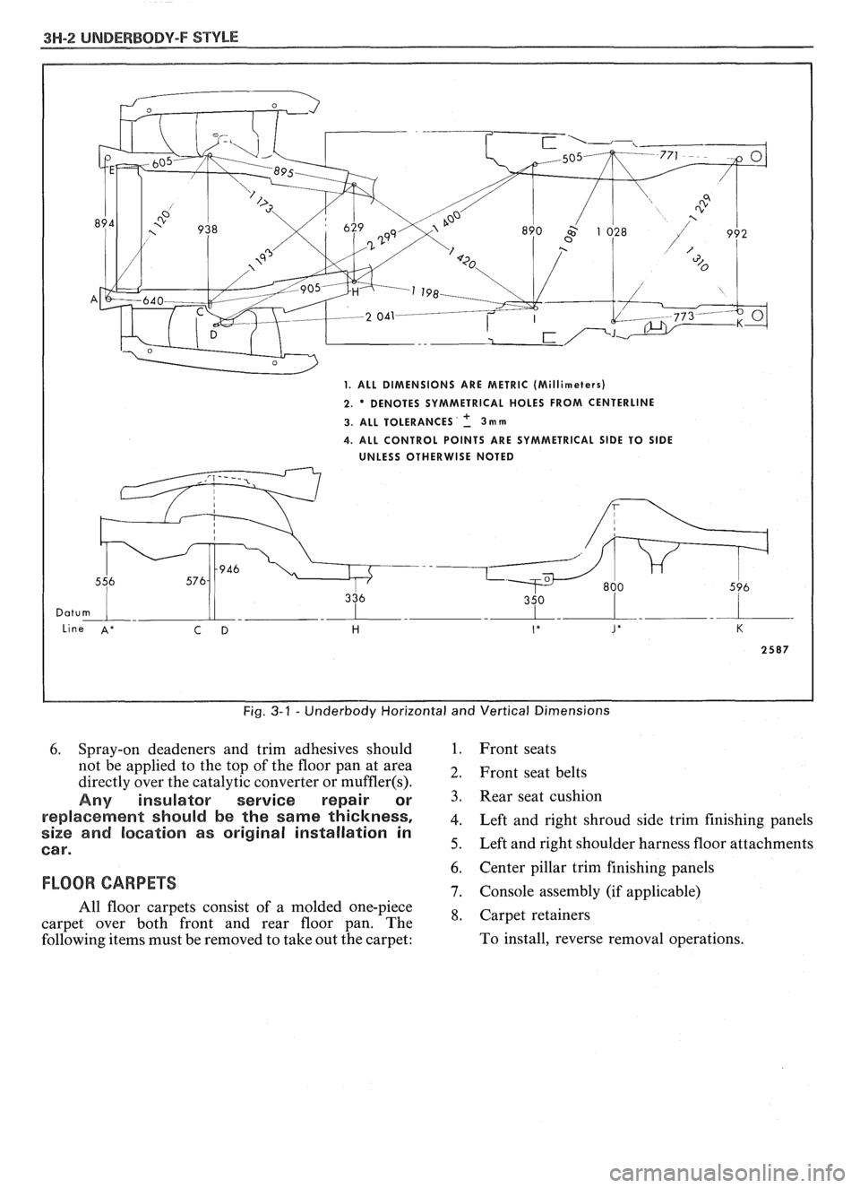
Two types of measurements can be made with
a
tram gage: direct point-to-point measurements and
measurements calculated on a horizontal
vlane (datum
line) parallel to the underbody. In the
latter case, the
vertical pointers must be set as specified for each point
to be measured (Fig. 3-1).
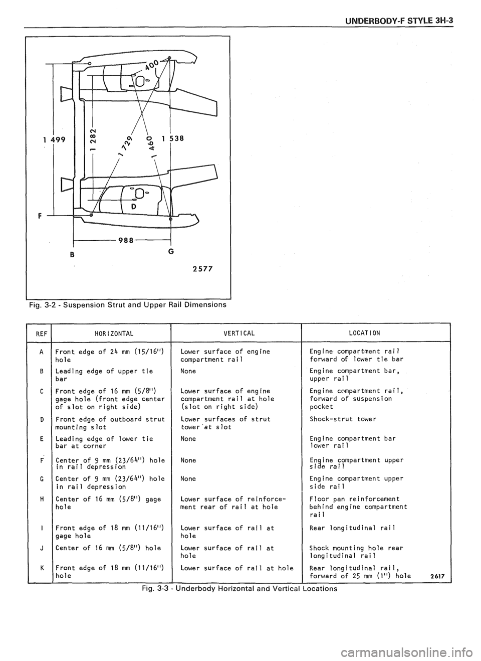
Point-to-point measurements are generally taken
only on engine compartment components (Fig. 3-2)
and simply require the vertical pointers to be equally
set.
Figure #3-3 describes the alphabetically
identified points of measurement. Figure 3-4 provides Floor
pan insulators have been designed for the
higher floor pan temperatures that result from the use
of the catalytic converter in the exhaust system.
Therefore, when servicing a vehicle in the field, it is
essential that any insulators that may have been
disturbed or removed be reinstalled in the original
sequence and location. Also, if it becomes necessary to
replace an insulator, the material specified for that
particular location on the floor pan must be used. The
types of materials are listed below. Items 1 and
2 are
rolled stock and are ordered by linear foot and cut to
fit.
1. Insulator floor pan
(cerra blanket thermal) -
consists of 10 mm (3/8") thick aluminum silica
(type 1).
2. Insulator floor pan (amberlite) - consists of 10
mm
(3/8") thick resinated fibers (type 2).
3. Insulator floor pan sheet (phenolic bonded fiber
glass)
305 mm x 457 mm (12" x 18") cut to size,
(type 3).
All of the above materials must meet
Motor Vehicle Safety Standard No. 302 for
flammability.
When servicing or replacing interior insulators,
the following instructions must be observed:
1. Insulators must be installed in the original
position and sequence. Pieces should be butted
together in order to avoid gapping or
overlapping.
2. If it is necessary to replace an insulator, the
specified material must be used.
3. Use original
part to determine the amount of
replacement material required and as a template
for cutting and fitting the new piece to the floor
pan.
4. When installing insulator, do not enlarge cutouts
or holes that are used for the attachment of
interior components such as seats or seat belts.
5. Cross body harnesses for interior components
such as power seats, lap belt warning light and
buzzer or rear speakers must be routed over the
floor pan insulators in the original location and
clipped in place.
Page 1707 of 1825
3H-2 UNDERBODY-F STYLE
Fig. 3-1 - Underbody Horizontal and Vertical Dimensions
6. Spray-on deadeners and trim adhesives should 1. Front seats
not be applied to the top of the floor pan at area
2, Front seat belts directly over the catalytic converter or muffler(s).
Any insulator service repair or 3. seat cushion
re~laeement should be the same thickness, 4. Left and right shroud side trim finishing panels size and location as original installation in
Car. 5. Left and right shoulder harness floor attachments
6. Center pillar trim finishing panels
FLOOR CARPETS 7. Console assembly (if applicable)
All floor carpets consist of a molded one-piece
*, Carpet retainers carpet over both front and rear floor pan. The
following items must be removed to take out the carpet: To
install, reverse removal operations.
Page 1708 of 1825
UNDERBODY-F STYLE 3H-3
Fig. 3-2 - Suspension Strut and Upper Rail Dimensions
Front edge of 24 mm (15/16") " ( hole
Leading edge of upper tie
( bar
C Front edge of 16 mm (5/811) gage hole (front edge center
of slot on right side)
I
Front edge of outboard strut
mounting slot
I
Leading edge of lower tie
bar at corner
F Center of 9 mm (23/6411) hole
in rail depression
G Center of 9 mm (23/6411) hole
in rail depression
H Center of 16 mm (5/811) gage / hole
I Front edge of 18 mm (11/16'~) gage hole
J Center of 16 mm (5/811) hole
Front edge of
18 mm (11/16") I hole Lower
surface of engine
compartment rail
None
Lower
compar
(slot surface
of engine
.tment rail at hole
on right side)
Lower surfaces of strut
tower 'at slot
None
None
None
Lower surface of reinforce-
ment rear of rail at hole
Lower surface of rail at
hole
Lower surface of rail at
hole
I Lower surface of rail at hole Eng
ine compartment rai
1 forward of lower tie bar
Engine compartment bar,
upper rai
1
Engine compartment rail,
forward of suspension
pocket
Shock-strut tower
Engine compartment bar
lower rail
En ine compartment upper
si e rail
I%
Engine compartment upper
side rail
Floor pan reinforcement
behind engine compartment
rai
1
Rear longitudinal rail
Shock mounting hole rear
longitudinal rail
I
Rear longitudinal rail,
forward of 25 mm (1") hole 2617
Fig. 3-3 - Underbody Horizontal and Vertical Locations
Page 1709 of 1825
3H-4 UNDERBODY-F STYLE
D IHENS ION
A to A A to C B to G C to C C to A C to E C to H Right C to H Left D to D
D to G D to I F to F F to G
G to G G to D H to H H Right to C Left H Left to C Right H to I I to I I to D I Right to H Left I Left to H Right I to J
J to J J to I J to K Right J to K Left K to K K Right to J Left K Left to J Right
=ig. 3-4 - Metric-to-English Dimension Conversion Chart
Page 1710 of 1825
FRONT END - F STYLE 41-1-1
SECTION 4H
FRONT END
NOTICE: The anti-theft label found on some major sheet metal, engines, and transmissions must be masked
prior to painting, rustproofing, undercoating, etc. The
mask must be removed following the above operations.
Failure to keep the label clean and readable may result in liability for violation of Federal Vehicle Theft Prevention
Standard, and subject the vehicle owner to possible suspicion that the part was stolen.
CONTENTS
.............................................................................................................. Body Ventilation 4H- 1
Shroud Side Trim Finishing Panel ................................................................................ 4H- 1
Pressure Relief Valve .................................................................................................. 4H- 1
Hood Latch Release Cable ............................................................................................ 4H- 1
The body ventilation system on styles without air
conditioning consists of a fresh air intake located at the
front plenum chamber. Air enters the front plenum
chamber through an air intake grille screen (Fig.
1).
Air passes through the plenum chamber to air outlet
doors. When ventilation controls are operated, air
enters past the doors and into the body from outlets in
the dash panel. The air then passes through the body,
around the rear seat, into the rear compartment to the
rear quarters and leaves the body passing through the
pressure relief valves on the rear body lock pillars (Fig.
4). For complete instructions on operation of the body
ventilation system, refer to the owner's manual.
Water entering the plenum chamber is drained
through openings provided for that purpose.
FRONT END SEALING
All potential waterleak locations are sealed in
production with high quality durable sealers. Should it
be necessary to reseal specific areas, a high quality
medium-bodied sealer which will remain flexible after
curing and can be painted should be used.
SHROUD SIDE TRIM FINISHING PANEL
Removal and Installation
1. Remove shroud side trim finishing panel screws
(Fig. 2).
2. Pull down and rearward on trim finishing panel
to release hood cable handle from slot on left side.
On right side, pull rearward to remove panel from
windshield lower side garnish (Figs.
2 and 3).
3. To install, reverse removal procedures.
PRESSURE RELIEF VALVE
The pressure relief valves are attached to rear
lock pillars (in door opening below belt) with screws.
Figure
4 shows pressure relief valve installations.
Removal and Installation
1. Remove louver-to-lock pillar screw located in the
door opening (Fig.
4).
2. Slide louver up to disengage hook-type attaching
clip to complete removal.
3. To install, reverse removal procedure.
HOOD LATCH RELEASE CABLE
The one-piece hood latch release cable includes
pull handle, control cable and housing. The control
cable is installed through the left shroud side trim
panel. A sealing grommet attached to the dash panel
completes the assembly (Figs. 2 and
5).
Removal and Installation
The shroud side finishing panels are designed
with an integral hinge pillar pinchweld finishing lace.
The left side has a cutout slot for the hood release cable
handle. There is no need to remove the cable assembly
2.
when removing the trim finishing panel. The trim 3.
finishing panel is secured to the side shroud with
self-tapping attaching screws.
4.
Raise hood and disengage cable from hood latch
assembly. Block latch to prevent hood locking
until cable has been reinstalled.
Remove left shroud side trim panel.
Disengage control assembly housing from cutout
of trim panel and remove
cable assembly from
panel.
To install, reverse the removal procedure.