boot PONTIAC FIERO 1988 Service User Guide
[x] Cancel search | Manufacturer: PONTIAC, Model Year: 1988, Model line: FIERO, Model: PONTIAC FIERO 1988Pages: 1825, PDF Size: 99.44 MB
Page 337 of 1825
582.2 POWER HEAD ASSEMBLY
GENERAL DESCRIPTION
This booster is a tandem vacuum suspended unit.
In a normal operating mode, with the service brakes in
the released position, the tandem vacuum suspended
booster operates with vacuum on both sides of its
diaphragms. When the brakes are applied, air at
atmospheric pressure is admitted to one side of each
diaphragm to provide the power assist. When the
service brake is released, the atmospheric air is shut off
from the one side of each diaphragm. The air is then
drawn from the booster through the vacuum check
valve to the vacuum source.
important
e Replace all components included in repair kits
used to service this booster.
e Lubricate rubber parts with silicone grease,
provided in kits, to ease assembly.
o Do not use lubricated shop air on brake parts as
damage to rubber parts may result.
o If any hydraulic component is removed or
disconnected, it may be necessary to bleed all or
part of the brake system.
e The torque values specified are for dry,
unlubricated fasteners.
Perform service operations on a clean bench free
from all mineral oil materials.
ON-CAR SERVICE
BOOSTER ASSEMBLY
(Figure 2)
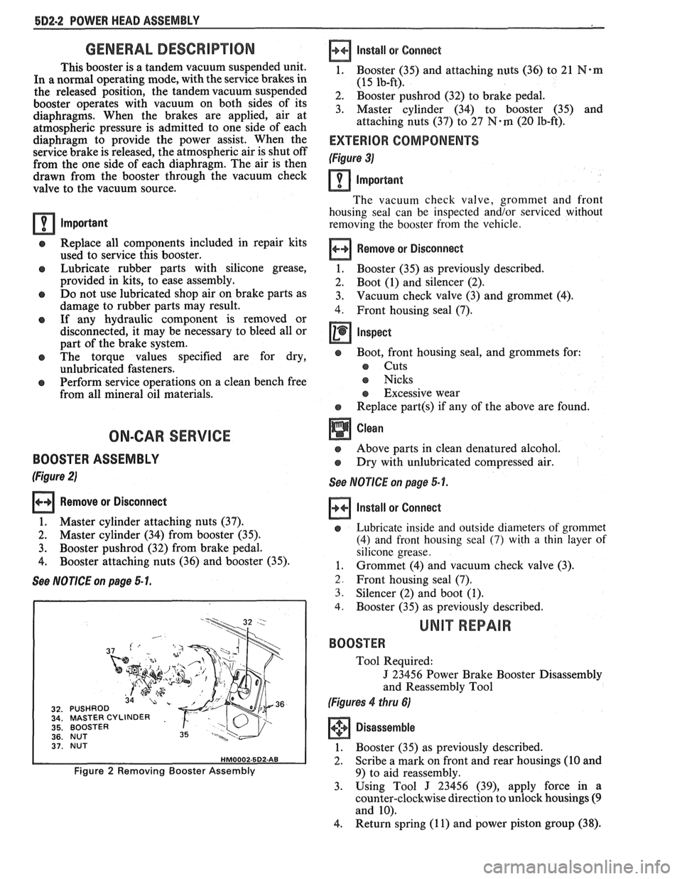
Remove or Disconnect
1. Master cylinder attaching nuts (37).
2. Master cylinder (34) from booster (35).
3. Booster pushrod (32) from brake pedal.
4. Booster attaching nuts (36) and booster (35).
See NOTICE on page 5 1.
MASTER CYLINDER
BOOSTER
NUT
BOOSTER
Figure 2 Removing Booster Assembly
Install
or Connect
1, Booster (35) and attaching nuts (36) to 21 N*m
(15 lb-ft).
2. Booster pushrod (32) to brake pedal.
3. Master cylinder (34) to booster (35) and
attaching nuts (37) to
27 N-m (20 lb-ft).
EXTERIOR COMPONENTS
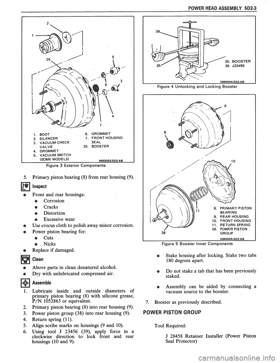
(Figure 3)
Important
The vacuum check valve, grommet and front
housing seal can be inspected and/or serviced without
removing the booster from the vehicle.
Remove or Disconnect
1. Booster (35)
as previously described.
2. Boot (1) and silencer (2).
3. Vacuum check
valve (3) and grommet (4).
4. Front housing seal (7).
Inspect
e Boot, front housing seal, and grommets for:
s Cuts
s Nicks
s Excessive wear
e Replace part(s) if any of the above are found.
Above parts in clean denatured alcohol.
Dry with unlubricated compressed air.
See NOTICE on page 5-1.
Install or Connect
e Lubricate inside and outside diameters of grommet
(4) and front housing seal
(7) with a thin layer of
silicone grease.
1. Grommet (4) and vacuum check valve (3).
2. Front housing seal (7).
3. Silencer (2) and boot (1).
4. Booster (35) as previously described.
UNIT REPAIR
BOOSTER
Tool Required:
J 23456 Power Brake Booster Disassembly
and Reassembly Tool
(Figures 4 thru 6)
Disassemble
1. Booster (35) as previously described.
2. Scribe a mark on front and rear housings (10 and
9) to aid reassembly.
3. Using Tool
J 23456 (39), apply force in a
counter-clockwise direction to unlock housings
(9
and 10).
4. Return spring
(1 1) and power piston group (38).
Page 338 of 1825
POWER HEAD ASSEMBLY 5D2-3
1. BOOT 6. GROMMET 2. SILENCER 7. FRONT HOUSING 3. VACUUM CHECK SEAL VALVE 35. BOOSTER
Figure 3 Exterior Components
5. Primary piston bearing (8) from rear housing (9).
Inspect
e Front and rear housings:
e Corrosion
e Cracks
e Distortion
e Excessive wear
e Use crocus cloth to polish away minor corrosion.
e Power piston bearing for:
e Cuts
e Nicks
e Replace if damaged.
Clean
e Above parts in clean denatured alcohol.
e Dry with unlubricated compressed air.
Assemble
1. Lubricate inside and outside diameters of
primary piston bearing (8) with silicone grease,
P/N 1052863 or equivalent.
2. Primary piston bearing (8) into rear housing (9).
3. Power piston group (38) into rear housing (9).
4. Return spring (1 1).
5. Align scribe marks on housings (9 and 10).
6. Using tool
J 23456 (39), apply force in a
clockwise direction to lock front and rear
housings (10 and 9).
8. PRIMARY PISTON BEARING 9. REAR HOUSING 10. FRONT HOUSING 11. RETURN SPRING 38. POWER PISTON
Figure 5 Booster Inner Components
e Stake housing after locking. Stake two tabs
180 degrees apart.
e Do not stake a tab that has been previously
staked.
e Assembly can be aided by connecting a
vacuum source to the booster.
7. Booster as previously described.
POWER PISTON GROUP
Tool Required:
J 28458 Retainer Installer (Power Piston
Seal Protector)
Page 345 of 1825
5F-2 SPECIFICATIONS AND SPECIAL TOOLS
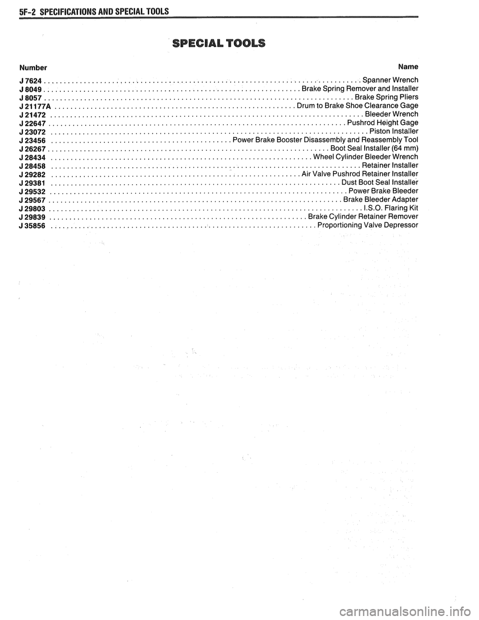
SPECIAL TOOLS
Number Name
J7624 ............................................................................... Spannerwrench
................................................................ J 8049 Brake Spring Remover and Installer
J8057 ............................................................................. Brakespringpliers
J21177A ............................................................ DrumtoBrakeShoeClearanceGage
J21472 .............................................................................. Bleederwrench
J22647 .......................................................................... PushrodHei ghtGage
J23072 ............................................................................... Pistonlnstailer
............................................. J 23456 Power Brake Booster Disassembly and Reassembly Tool
J26267 ...................................................................... BootSeallnstaller(64mm)
J28434 ................................................................. WheelCylinderBleederWrench
J28458 ............................................................................. Retainerlnstaller
.............................................................. J 29282 Air Valve Pushrod Retainer Installer
........................................................................ J 29381 Dust Boot Seal Installer
J29532 .......................................................................... PowerBrakeBleeder
J29567 ......................................................................... Br akeBleederAdapter
J29803 .............................................................................. 1.S.O.FlaringKit
................................................................ J 29839 Brake Cylinder Retainer Remover
.................................................................. J 35856 Proportioning Valve Depressor
Page 470 of 1825
IGNITION SYSTEM 6D4-1
ON SYSTEM
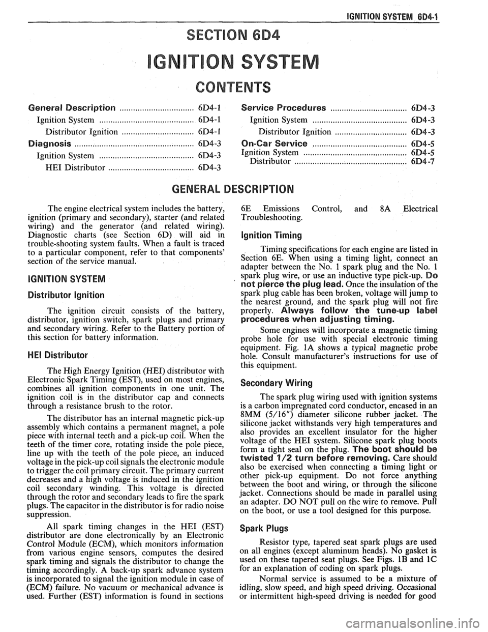
CONTENTS
General Description ............................... 6D4-1 Service Procedures ............................. 6D4-3
Ignition System .......................................... 6D4-1
Ignition System .......................................... 6D4-3
Distributor Ignition ................................ 6D4-1
Distributor Ignition ................................ 6D4 -3
Diannosis .................................................... 6D4-3 On-Car Service ......................................... 6D4-5 -
Ignition System .......................................... (334-3 Ignition System ........................... .. .............. 6D4-5
Distributor ................................................. 6D4 -7 HE1 Distributor .................................... 6D4-3
GENERAL DESCRIPION
The engine electrical system includes the battery,
ignition (primary and secondary), starter (and related
wiring) and the generator (and related wiring).
Diagnostic charts (see Section 6D) will aid in
trouble-shooting system faults. When a fault is traced
to a particular component, refer to that components'
section of the service manual.
IGNITION SYSTEM
Distributor Ignition
The ignition circuit consists of the battery,
distributor, ignition switch, spark plugs and primary
and secondary wiring. Refer to the Battery portion of
this section for battery information.
PIE1 Distributor
The Nigh Energy Ignition (HEI) distributor with
Electronic Spark Timing (EST), used on most engines,
combines all ignition components in one unit. The
ignition coil is in the distributor cap and connects
through a resistance brush to the rotor.
The distributor has an internal magnetic pick-up
assembly which contains a permanent magnet, a pole
piece with internal teeth and a pick-up coil. When the
teeth of the timer core, rotating inside the pole piece,
line up with the teeth of the pole piece, an induced
voltage in the pick-up coil signals the electronic module
to trigger the coil primary circuit. The primary current
decreases and a high voltage is induced in the ignition
coil secondary winding. This voltage is directed
through the rotor and secondary leads to fire the spark
plugs. The capacitor in the distributor is for radio noise
suppression,
All spark timing changes in the
HE1 (EST)
distributor are done electronically by an Electronic
Control Module (ECM), which monitors information
from various engine sensors, computes the desired
spark timing and signals the distributor to change the
timing accordingly.
A back-up spark advance system
is incorporated to signal the ignition module in case of
(ECM) failure. No vacuum or mechanical advance is
used. Further (EST) information is found in sections 6E
Emissions Control, and
8A Electrical
Troubleshooting.
Ignition Timing
Timing specifications for each engine are listed in
Section
6E. When using a timing light, connect an
adapter between the No. 1 spark plug and the No. 1
spark plug wire, or use an inductive type pick-up.
Do
not pierce the plug lead.
Once the insulation of the
spark plug cable has been broken, voltage will jump to
the nearest ground, and the spark plug will not fire
properly.
Always follow the tune-up label
procedures when adjusting timing.
Some engines will incorporate a magnetic timing
probe hole for use with special electronic timing
equipment. Fig.
1A shows a typical magnetic probe
hole. Consult manufacturer's instructions for use of
this equipment.
Secondary Wiring
The spark plug wiring used with ignition systems
is a carbon impregnated cord conductor, encased in an
8MM (5/16") diameter silicone rubber jacket. The
silicone jacket withstands very high temperatures and
also provides an excellent insulator for the higher
voltage of the
HE1 system. Silicone spark plug boots
form a tight seal on the plug.
The boot should be
twisted 1/2 turn before removing. Care should
also be exercised when connecting a timing light or
other pick-up equipment. Do not force anything
between the boot and wiring, or through the silicone
jacket. Connections should be made in parallel using
an adapter. DO NOT pull on the wire to remove. Pull
on the boot, or use a tool designed for this purpose.
Spark Plugs
Resistor type, tapered seat spark plugs are used
on all engines (except aluminum heads). No gasket is
used on these tapered seat plugs. See Figs.
1B and 1C
for an explanation of coding on spark plugs.
Normal service is assumed to be a mixture of
idling, slow speed, and high speed driving. Occasional
or intermittent high-speed driving is needed for good
Page 473 of 1825
684.4 IGNITION SYSTEM
a spark plug wire from a spark plug, twist the 4. Do not wipe grease from module, or distributor
boot on the spark plug and pull
on the boot to base,
if same module is to be replaced.
remove the wire, or use a special tool designed to
remove spark plug boots.
Install or Connect
Remove or Disconnect
1. Ignition switch battery feed wire and tachometer
lead (if equipped) from distributor cap. Also
release the coil connectors from the cap. (DO
NOT use a screwdriver or tool to release the
locking tabs.)
2. Distributor cap by turning four screws
counterclockwise. Move cap out of the way.
3. Four-terminal ECM harness from distributor.
4. If necessary, remove secondary wires from cap,
release wiring harness latches and remove wiring
harness retainer. The spark plug wire numbers
are indicated on the retainer.
5. Distributor clamp screw and hold-down clamp.
6. Note position of rotor, then pull distributor up
until rotor just stops turning counterclockwise
and again note position of rotor.
To insure correct timing of the distributor,
the distributor must be INSTALLED with
the rotor correctly positioned as noted.
If the engine was accidentally cranked after the
distributor was removed, the following procedure can
be used for installing:
1. Remove No. 1 spark plug.
2. Place finger over No. 1 spark plug hole and crank
engine slowly until compression is felt.
3. Align timing mark on pulley to "0" on engine
timing indicator.
4. Turn rotor to point between No. 1 and No. 8
spark plug towers on distributor cap on V8
engines, between No. 1 and No. 6 on V6 engines,
and No.
1 and No. 4 on 4 cylinder engines.
5. Install distributor and connect ignition feed wire.
6. Install distributor cap and spark plug wires.
7. Check engine timing (see Set Ignition Timing).
Install or Connect
1. Insert distributor, positioning rotor as removed.
2. Distributor hold-down clamp and screw.
3. Wiring harness retainer and secondary wires, if
removed.
4. ECM harness connector.
5. Distributor cap.
6. Coil connectors.
7. Battery wire and tachometer lead, if equipped.
Module
It is not necessary to remove the distributor from
car.
Remove or Disconnect
1. Distributor cap and rotor.
2. Two module attaching screws, and lift module
UP. 3. Leads from module. (Observe color code on leads
as these cannot be interchanged.)
NOTICE: If a new module is to be installed, a
package of silicone grease will be included with it.
Spread the grease on the metal face of the module
and on the distributor base where the module
seats. This grease is necessary for module cooling.
1. Module.
2. Module leads (observe color code).
3. Attaching screws to module.
4. Rotor.
5. Cap.
Pick-Up Coil
1. Remove distributor from car and follow
instructions in Unit Repair, as applicable.
Rotor
Fig. 1
1. Remove distributor cap.
2. The rotor is retained by two screws and is
provided with a slot which fits over a square lug,
,
so that the rotor can be installed in only one
position.
Integral Ignition Coil
Fig. I
Remove or Disconnect
1. Distributor cap.
2. Three coil cover attaching screws, and lift off
cover.
3. Coil attaching screws and lift ignition coil and
leads from cap.
Install or Connect I
1. Coil and attaching screws.
2. Coil leads.
3. Coil cover and attaching screws.
Capacitor
Fig. 1
The capacitor is part of the coil wire harness
assembly. Since the capacitor is used only for radio
noise suppression, it will seldom need replacement.
Remove or Disconnect I
1. Distributor cap and rotor.
2. Capacitor attaching screw and unplug connector
from module. It may help to loosen the module.
Install or Connect I
1. Plug into module.
2. Capacitor and hold-down screw (be sure ground
lead is under screw).
Page 474 of 1825
IGNITION SYSTEM 6014.5
3. Rotor and cap. 4. Turn off the engine and remove the timing light.
Reconnect the number one spark plug wire, if
Set Ignition Timing removed.
Spark Plug Wires 1. Refer to the tune-up label located in the engine
compartment. Follow all instructions on the Use
care when removing spark plug wire boots
label. from
spark plugs. Twist the boot
1/2 turn before
removing and pull on the
boot only to remove the
With ignition off, connect the pick-up lead of
timing light to the number one spark plug. Use
a jumper lead between the wire and plug, or an
inductive type pick-up.
DO NOT pierce the wire,
or attempt to insert a wire between the boot and
the wire. Connect the timing light power leads
according to manufacturer's instructions.
Start the engine and aim the timing light at the
timing mark. The line on the balancer or pulley
will line up at the timing mark. If a change is
necessary, loosen the distributor hold-down
clamp bolt at the base of the distributor. While
observing the mark with the timing light, slighty
rotate the distributor until the line indicates the
correct timing. Tighten the hold-down bolt and
re-check the timing. wire.
When replacing plug wires, route the wires
correctly and through the proper retainers. Failure to
route the wires properly can lead to radio ignition noise
and crossfiring of the plugs, or shorting of the leads to
ground.
Special care should be exercised when reinstalling
spark plug boots, to assure that the metal terminal
within the boot is fully seated on the spark plug
terminal and that the boot has not moved on the wire.
If boot to wire movement has occurred, the boot will
give a false visual impression of being fully seated.
A
good check to assure that boots have been properly
assembled is to push sideways on the installed boots.
If they have been correctly installed, a stiff boot, with
only slight looseness, will be noted. If the terminal has
not been properly seated on the spark plug, only the
resistance of the rubber boot will be felt when pushing
sideways.
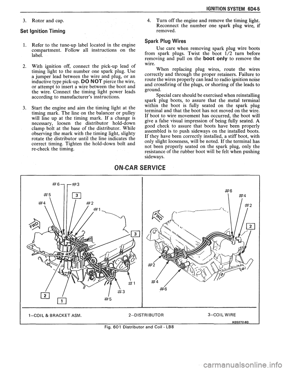
ON-CAR SERVICE
I I -COI L & BRACKET ASM. 2-DISTRIBUTOR 3-COIL WIRE I
Fig. 601 Distributor and Coil - LB8
Page 1140 of 1825
5-SPEED 77MM TRANSMISSION 7B-3
ON-VEHICLE SERVICE
SHlR CONTROL LEVER
Remove or Disconnect
1. Screws from transmission shift lever boot
retainer and slide boot up lever.
2. Shift lever attaching bolts at transmission and
remove lever.
NOTICE: The upper lever is no longer threaded
to the lower lever. The levers are bonded
together. Separation of the levers will damage the
shifter requiring replacement of the shifter
assembly.
Install or Conned
1. Shift lever and attaching bolts to transmission.
2. Shift lever boot, boot retainer and retainer
screws to transmission.
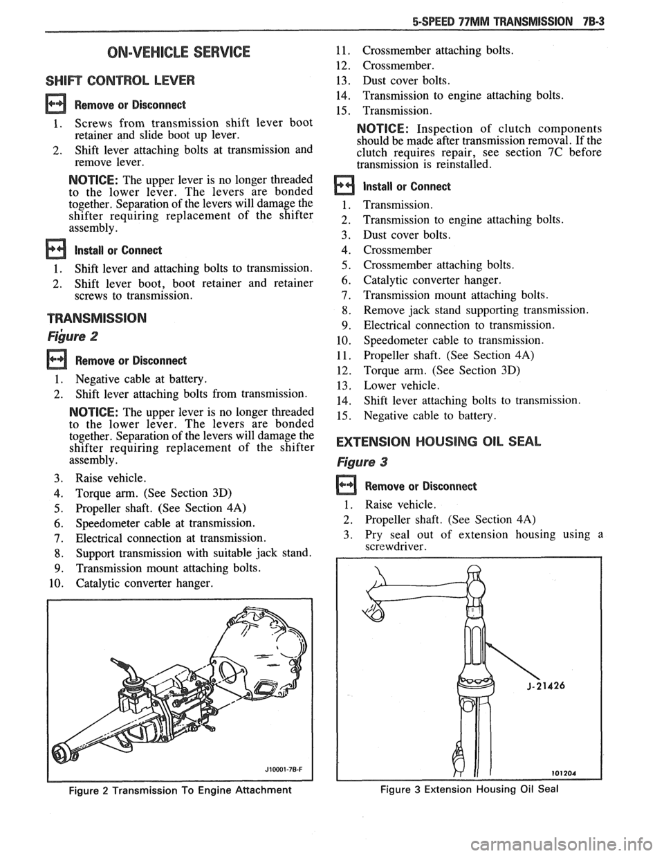
~ibure 2
Remove or Disconnect
1. Negative cable at battery.
2. Shift lever attaching bolts from transmission.
NOTICE: The upper lever is no longer threaded
to the lower lever. The levers are bonded
together. Separation of the levers will damage the
shifter requiring replacement of the shifter
assembly.
3. Raise vehicle.
4. Torque arm. (See Section 3D)
5. Propeller shaft. (See Section 4A)
6. Speedometer cable at transmission.
7. Electrical connection at transmission.
8. Support transmission with suitable jack stand.
9. Transmission mount attaching bolts.
10. Catalytic converter hanger.
Figure 2 Transmission To Engine Attachment
11. Crossmember attaching bolts.
12. Crossmember.
13. Dust cover bolts.
14. Transmission to engine attaching bolts.
15. Transmission.
NOTICE: Inspection of clutch components
should be made after transmission removal. If the
clutch requires repair, see section 7C before
transmission is reinstalled.
Install or Connect
Transmission.
Transmission to engine attaching bolts.
Dust cover bolts.
Crossmember
Crossmember attaching bolts.
Catalytic converter hanger.
Transmission mount attaching bolts.
Remove jack stand supporting transmission.
Electrical connection to transmission. Speedometer cable to transmission.
Propeller shaft. (See Section
4A)
Torque arm. (See Section 3D)
Lower vehicle.
Shift lever attaching bolts to transmission.
Negative cable to battery.
EXTENSlOM HOUSING OIL SEAL
Figure 3
Remove or Disconnect
1 . Raise vehicle.
2. Propeller shaft. (See Section 4A)
3. Pry seal out of extension housing using a
screwdriver.
Figure 3 Extension Housing Oil Seal
Page 1159 of 1825
7C-2 CLUTCH
PRELIMINARY CHECKS
Before attempting to repair the clutch,
transmission or related hydraulic components for any
reason other than
an obvious failure, the problem and
probable cause should be identified.
A large percentage
of clutch and manual transmission
problenls are
manifested by shifting difficulties such as high shift
effort, gear clash and grinding or transmission
blockout. When any of these problems occur, a careful
analysis of these difficulties should be accomplished
and the following checks and adjustments performed
in the presented sequence before removing the clutch
or transmission for repairs.
Before
removal of the clutch hydraulic system,
verify the malfunction by renloving the clutch housing
dust shield and
measure the travel of the clutch slave
cylinder push rod. With clutch pedal pushed fully to
the floor, the
slave cylinder push rod should extend
14.53mm (0.57 inch) minimum against the clutch
release lever. Do
not replace the hydraulic system if
push rod travel exceeds this distance.
If slave cylinder does not meet the travel require-
ments, check the reservoir fluid level. The slave cylinder
must be in place when checking the fluid level. The proper
level is indicated by a step on the reservoir. Fill to the
specified level with
GM Delco Supreme No. 11 Brake
Fluid or an equivalent fluid that meets DOT
3 specifica-
tions. Do not overfill. The upper portion of the reservoir
must accept fluid that is displaced from the slave cylinder
as the clutch wears.
NOTICE: Carefully clean the top and sides of the
reservoir before opening to prevent contamination of
the system with dirt, water or other foreign material.
Remove the reservoir diaphragm before adding fluid.
Carefully replace the diaphragm, cover gasket and
cover after filling.
If the reservoir requires any fluid, check the
hydraulic system components for leakage. Remove the
rubber boots from the cylinder and check for leakage
past the pistons. A slight wetting of the surfaces is
acceptable. Replace the system, if excessive leakage is
evident.
BLEEDING CLUTCH SYSTEM
allowed to fall so low that air has been drawn into the
master cylinder.
NOTICE: Never, under any circumstances, use
fluid which has been bled from a system to fill the
reservoir as it may be aerated, have too much
moisture content and possibly be contaminated.
Clean dirt and grease from the cap to ensure no
foreign substances enter the system.
Remove cap and diaphragm and
fill reservoir to
the top with approved brake fluid only. (Brake
fluid must be certified to DOT 3 specifications).
Fully loosen bleed screw which is in the slave
cylinder body next to the inlet connection.
Fluid will now begin to move from the master
cylinder down the tube to the slave. It is
important that for efficient gravity
fill, the
reservoir must be kept full at all times.
It will be noticeable at this point that bubbles will
appear at the bleed screw outlet. This means that
air is being expelled. When the slave is full, a
steady stream of fluid will come from the slave
outlet. At this point tighten bleed screw to a
torque of 2
N .m.
Assemble diaphragm and cap to the reservoir,
fluid in reservoir should be level with step.
Exert a light load (approximately 20 lbs.) to the
slave cylinder piston by pushing release lever
towards the cylinder and loosen bleed screw.
Maintain a constant light load, fluid and any air
that is left will be expelled through the bleed port.
Tighten bleed screw when a steady flow of fluid
and no air is being expelled.
Renew fluid level in reservoir, assemble
diaphragm and cap. If necessary, repeat Steps
7
and 8.
Exert light load to release lever as in Step 7 (do
not open bleed screw), piston in slave will move
slowly down bore. Repeat 2-3 times, fluid
n~oven~ent will force any air left in the system into
the reservoir.
The hydraulic system should now be fully bled
and should release the clutch. Check vehicle by
starting, pushing clutch pedal to the floor and
selecting reverse gear. There should be no grating
of gears, if there is, the hydraulic system could
still contain air. If this is the case, repeat bleed
The process of removing air from the
line and procedure.
cylinders is known as "bleeding" and is necessary Check push rod travel at the
slave cylinder to insure
whenever the level of fluid in the reservoir has been the minimum travel
of
14.53mm (0.57 inch) for V-8
and 1 lrnm (0.43 inch) for V-6.
Page 1163 of 1825
7C-6 CLUTCH
6. Clutch master cylinder push rod to clutch pedal.
7. Install brake switch.
8. Install hush panel.
9. Install steering column trim cover.
10. Install clutch reservoir to bracket.
1 1. Hoist vehicle.
12. Pilot slave cylinder into clutch fork.
NOTICE: With a new system, the slave cylinder
contains a shipping strap that pre-positions the
push rod for installation, and also provides a
bearing insert.
Follojving installation of the slave
cylinder, the first actuation of the clutch pedal will
break the shipping strap and give
normal system
operation.
13. Install slave cylinder and heat shield to bell
housing.
14.
Lojver vehicle.
15. Connect negative battery cable.
CLUTCH ASSEMBLY
Removal
1. Remove the transmission as outlined in
transmission section.
2. Remove the slave cylinder heat shield and slave
cylinder
from flywheel housing.
3. Reniove the flywheel housing.
4. Slide clutch fork from ball stud and remove fork
from dust boot. Ball stud is threaded into clutch
housing and is easily replaced, if necessary.
5. Install Tool 5-33169 to support the clutch
assen~bly during removal. Look for mark or white
painted letter on clutch cover and
"X" mark on
flywheel. If
"Xu or letter is not evident, mark
flywheel and clutch cover for indexing purposes
during installation.
6. Loosen clutch-to-flywheel attaching bolts evenly
1 turn at a time until spring pressure is released.
7. Remove clutch and pressure plate assembly.
lnspection
Inspect the flywheel for cracks, heat checking or
other defects. Replace or repair as required.
Installation
Pressure plate and flywheel face, (They should be
free of oil, grease, metal deposits or burned spots.)
Installation
1. Position clutch disc and pressure plate in relative
installed position and support them with
alignment Tool J-33169 or a drive gear.
The driven disc is installed with the damper
springs to the transmission. The flywheel side is
marked.
2. Turn clutch assembly until "X" mark or white
painted letter on cover lines up with
"X" mark on flywheel,
then align cover bolt holes to nearest
flywheel holes.
3. Install a bolt in every hole and tighten down
evenly and gradually until tight to avoid possible
clutch distortion. (Cover loads are as high as
1- 1/4 tons).
4. Remove the pilot tool.
5. Unhook clutch fork and lubricate ball socket and
fork fingers at release bearing end with a high
melting point grease such as graphite and
reinstall fork on ball stud.
6. Lubricate recess on inside of release bearing
collar and the clutch fork groove with light coat
of graphite grease. Refer to Figure 7C-6.
7. Install the clutch fork and dust boot into clutch
housing and install release bearing to fork, then
install flywheel housing.
8. Install the transmission as outlined in
transmission section.
9. Install the clutch slave cylinder and bracket.
CLUTCH PEDAL
Removal
Disconnect the negative cable at battery.
Remove the steering column trim cover.
Remove the hush panel from under dash.
If equipped, disconnect cruise control switch at
clutch pedal.
Disconnect the neutral start switch at clutch
pedal.
Renlove the turn signal and hazard flasher
mounting bracket attaching screws.
Disconnect the clutch master cylinder push rod
from pedal.
Remove the nut from clutch pedal pivot bolt. Pull
bolt out far enough for pedal removal.
Inspection
Clean and inspect all components and replace as
necessary. Do not clean bushings with a cleaning
solvent, simply wipe with a clean cloth.
Relubricate all bushings and moving parts.
Installation
1. Reverse the removal procedure.
PILOT BEARING (FIGURE 7C-7)
Replacement
The clutch pilot bearing is an oil impregnated type
bearing pressed into the crankshaft. This bearing requires
attention when the clutch is removed from the vehicle, at
which time it should be cleaned and inspected for exces-
sive wear or damage and should be replaced if necessary.
To remove, install Tool
J 23907 and remove bearing
from crankshaft, as shown in Figure
7C-7. In replacing
this bearing, use Tool
J 1522. Place bearing on pilot of
tool with radius in bore of bearing next to shoulder on tool
and drive into crankshaft. Lubricate with several drops of
machine oil.
Page 1798 of 1825
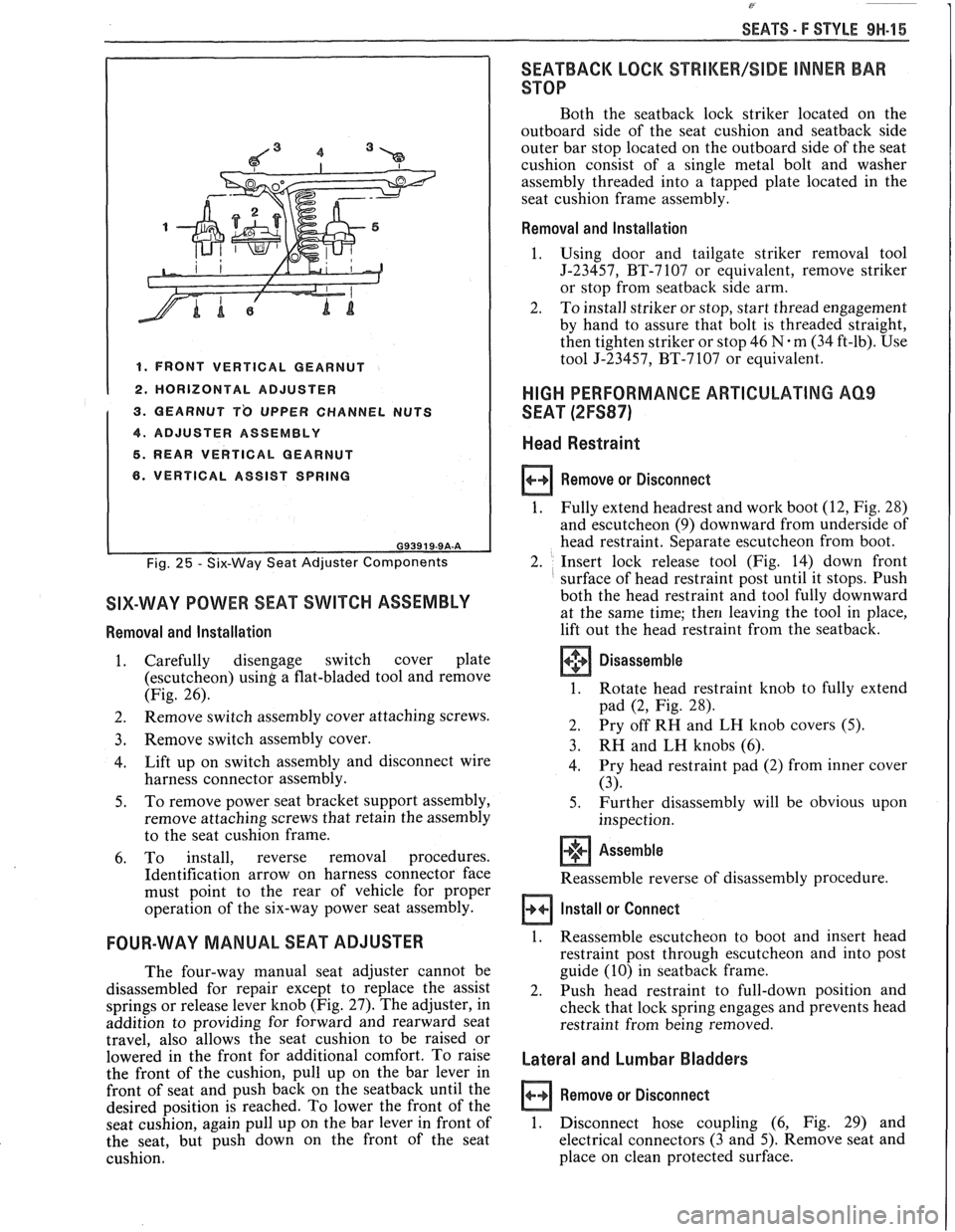
SEATS - F STYLE 9H-15
I 1. FRONT VERTICAL GEARNUT I 1 2. HORIZONTAL ADJUSTER
1 3. QEARNUT T'O UPPER CHANNEL NUTS
1 4. ADJUSTER ASSEMBLY I 5. REAR VERTICAL GEARNUT
6. VERTICAL ASSIST SPRING
Fig. 25 - Six-Way Seat Adjuster Components
SIX-WAY POWER SEAT SWITCH ASSEMBLY
Removal and Installation
1. Carefully disengage switch cover plate
(escutcheon)
using a flat-bladed tool and remove
(Fig. 26).
2. Remove
switch assembly cover attaching screws.
3. Remove switch assembly cover.
4. Lift
up on switch assembly and disconnect wire
harness connector assembly.
5. To
remove power seat bracket support assembly,
remove attaching screws that retain the assembly
to the seat cushion frame.
6. To install, reverse removal procedures.
Identification arrow on harness connector face
must point to the rear of vehicle for proper
operation of the six-way power seat assembly.
FOUR-WAY MANUAL SEAT ADJUSTER
The four-way manual seat adjuster cannot be
disassembled for repair except to replace the assist
springs or release lever knob (Fig.
27). The adjuster, in
addition to providing for forward and rearward seat
travel, also allows the seat cushion to be raised or
lowered in the front for additional comfort. To raise
the front of the cushion, pull up on the bar lever in
front of seat and push back on the
seatback until the
desired position is reached. To lower the front of the
seat cushion, again pull up on the bar lever in front of
the seat, but push down on the front of the seat
cushion.
SEATBACK LOCK %%RIMEW/SIDE INNER BAR
STOP
Both the seatback lock striker located on the
outboard side of the seat cushion and
seatback side
outer bar stop located on the outboard side of the seat
cushion consist of a single metal bolt and washer
assembly threaded into a tapped plate located in the
seat cushion frame assembly.
Removal and Installation
1.
Using door and tailgate striker removal tool
J-23457, BT-7107 or equivalent, remove striker
or stop from
seatback side arm.
2. To install striker or stop, start thread engagement
by hand to assure that bolt is threaded straight,
then tighten striker or stop 46
N.m (34 ft-lb). Use
tool J-23457, BT-7107 or equivalent.
HIGH PERFORMANCE ARTICULATING AQ9
SEAT (2FS87)
Head Restraint
Remove or Disconnect
1.
Fully extend headrest and work boot (12, Fig. 28)
and escutcheon
(9) downward from underside of
head restraint. Separate escutcheon from boot.
2. Insert lock release tool (Fig. 14) down front
surface of head restraint post until it stops. Push
both the head restraint and tool fully downward
at the same time;
then leaving the tool in place,
lift out the head restraint from the seatback.
Disassemble
1. Rotate head restraint knob to fully extend
pad
(2, Fig. 28).
2. Pry
off RH and LH knob covers
(5).
3. RH and LH knobs (6).
4. Pry
head restraint pad (2) from inner cover
(3).
5. Further disassembly will be obvious upon
inspection.
+'+ Assemble [I]
Reassemble reverse of disassembly procedure.
Install or Connect
1. Reassemble escutcheon to boot and insert head
restraint post through escutcheon and into post
guide (10) in
seatback frame.
2. Push head restraint to full-down position and
check that lock spring engages and prevents head
restraint from being removed.
Lateral and Lumbar Bladders
Remove or Disconnect
1. Disconnect hose coupling (6, Fig. 29) and
electrical connectors (3 and 5). Remove seat and
place on clean protected surface.