sensor PONTIAC FIERO 1988 Service Repair Manual
[x] Cancel search | Manufacturer: PONTIAC, Model Year: 1988, Model line: FIERO, Model: PONTIAC FIERO 1988Pages: 1825, PDF Size: 99.44 MB
Page 1277 of 1825
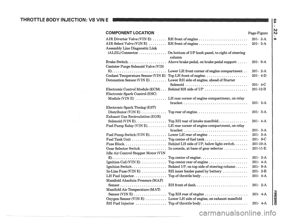
THROTTLE BODY INJECTION: V8 VIN E
COMPONENT LOCATION Page-Figure
AIR Diverter Valve (VIN E)
....... RH front of engine .........................
AIR Select Valve (VIN E) ......... RH front of engine .........................
Assembly Line Diagnostic Link
(ALDL) Connector
.............. On bottom of IIP hush panel, to right of steering
column
Brake Switch.
................... Above brake pedal, on brake pedal support .....
Canister Purge Solenoid Valve (VIN
E)
............................ Lower LH front corner of engine compartment ..
Coolant Temperature Sensor (VIN E) Top LH front of engine. .....................
Detonation Sensor (VIN E) ........ Lower RK side of engine, ahead of Starter
Solenoid
................................
Electronic Control Module (ECM) ... Behind RH side of IIP ......................
Electronic Spark Control (ESC)
Module (VIN E)
................ LH rear corner of engine compartment, on relay
................................. bracket
Electronic Spark Timing (EST)
Distributor (VIN E)
............. Top rear of engine. .........................
Exhaust Gas Recirculation (EGR)
Solenoid (VIN E).
............... Top RH rear of intake manifold. ..............
Fuel Pump Relay (VIN E). ......... LH rear corner of engine compartment, on relay
................................. bracket
Fuel Pump Switch (VIN E).
........ Lower LH rear of engine ....................
Fuel Tank Unit .................. Top center of fuel tank. .....................
Fuse Block. ..................... Behind LH side of IIP, below light switch. ......
Gear Selector Switch ............. In console, at base of gear selector ............
Idle Air Control Stepper Motor (VIN
E)
............................ Topcenterofengine ........................
Ignition Coil (VIN E) ............. Top center rear of engine ....................
Ignition Switch. ................. Behind IIP, on top side of steering column ......
In-Line Fuse (VIN E) ............. RW inner fender panel by battery .............
LW Fuel Injector. ................ Top of throttle body. .......................
Manifold Absolute Pressure (MAP)
Sensor
........................ RH front of dash. ..........................
Manifold Air Temperature (MAT)
Sensor (VIN
E) ................. Top RK rear of engine ......................
Oxygen Sensor (VIN E) ........... Lower LH side of engine, on exhaust manifold
RH Fuel Injector
................ Top of throttle body. .......................
Page 1278 of 1825

THROTTLE BODY INJECTION: V8 VIN E
COMPONENT LOCATION Page-Figure
........................ Throttle Position Sensor (VIN E) ... Top center of engine 201- 4-A
............. Vehicle Speed Sensor Buffer ....... Behind RN side of IIP. near ECM 201-13-A
.. el00 (42 cavities) ................ LH front of dash. left of brake master cylinder 201- 0-A
...... C113 (1 cavity) (VIN E) ............ Taped to engine harness. RH front of dash 201- 2-A
............ C114 (1 cavity) (VIN E) Taped
to engine harness. above rear of engine
C143 (1 cavity) (VIN E) ............ Lower LH side of engine .................... 201- 3-A
C207 (15
cavities) ................ Behind RN side of IIP. near ECM ............. 201-13-A
C313
(3 cavities) ................. Below center of back seat .................... 201- 9-6
6112 (VIN E) ................... Rear of LH cylinder head .................... 201- 3-C
. 6118 (VIN E) ................... Rear of RH cylinder head .................... 201- 5-B
6200
.......................... Behind IIP. left of steering colulm ............ 201-10-A
6304
.......................... Under rear seat. on support bracket
S142 (VIN E) .................... Engine harness. behind RN side of IIP
S143 (VINE) .................... Engine harness. RH front of dash ............. 201- 2-A
S145
(VIN E) .................... Engine harness. above rear of engine .......... 201- 3-C
S146 (VIN E) .................... Engine harness. behind RH side of IIP
S164 ........................... IIP harness. above Fuse Block ................ 201-10-A
S166 (VINE) .................... Engine harness. above rear of engine .......... 201- 3-C
S172 (VIN E) .................... Engine harness. RN front of dash ............. 201- 2-8
S174 (VIN E) .................... Engine harness. RH front of dash ............. 201- 2-8
S175 (VIM E) .................... Engine harness. above LH rear of engine ....... 201- 3-A
S176
(VIN E) .................... Engine harness. behind RH side of IIP
S186 ........................... Engine harness. R W. front of dash ............. 281- 2-A
S201
........................... IIP harness. behind instmmend cluster ......... 201-10-A
S202 ........................... IIP harness. behind RH side of IIP ............ 201-13-A
S204 ........................... IIP harness. be&d instnnment cluster ......... 201-10-A
S205
........................... IIP harness. behind instrument cluster ......... 201-10-A
S217 ........................... IIP harness. bebd center of IIP .............. 201-18-A
S218
........................... Engine harness. lower RH comer of engine
compartment
............................ 201- 2-8
S242 ........................... IIP harness. bebd RH side of IIP ............ 201-13-A
S276 ........................... IIP harness. behind RW side of Ill? ............ 201-13-A
Page 1281 of 1825
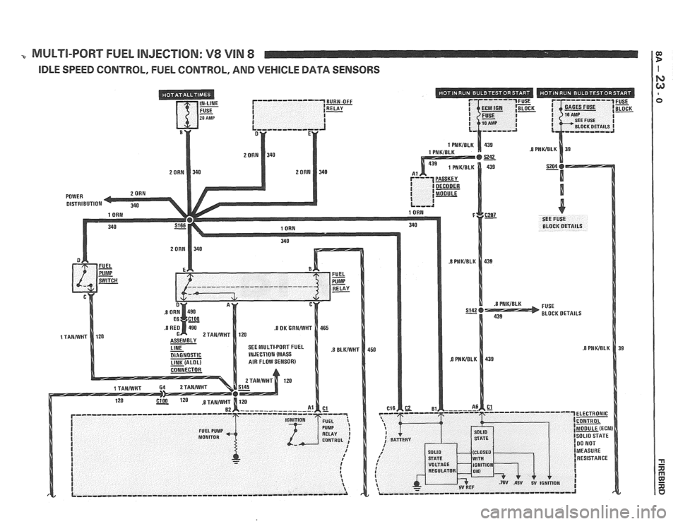
MULTI-PORT FUEL INJECTION: V8 VIN 8
IDLE SPEED CONTROL, FUEL CONTROL, AND VEHICLE DATA SENSORS
Page 1285 of 1825
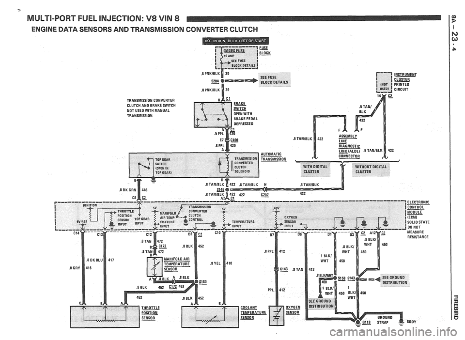
MULTI-PORT FUEL INJECTION: V8 VIN 8
ENGINE DATA SENSORS AND TRANSMlSSlOlU CONVERTER CLUTCH
Page 1286 of 1825
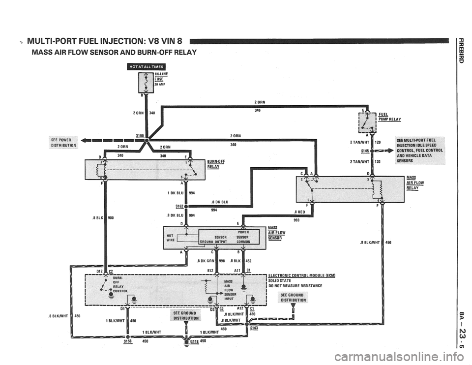
-c MULTI-PORT FUEL INJECTION: V8 VIN 8
MASS AIR FLOW SENSOR AND BURN-OFF RELAY
Page 1289 of 1825
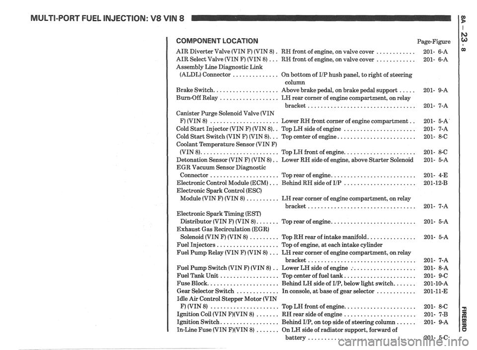
MULTI-PORT FUEL INJECTION: V8 VIN 8 It
COMPONENT LOCATION Page-Figure
. ............ AIR Diverter Valve (VIN F) (VIN 8)
RN front of engine. on valve cover 201- 6-A
............ AIR Select Valve (VIN F) (VIN 8) ... RW front of engine. on valve cover 201- 6-A
Assembly Line Diagnostic Link
(ALDL) Connector
.............. On bottom of I/P hush panel. to right of steering
column
..... Brake Switch .................... Above brake pedal. on brake pedal support 201- 9-A
Burn-Off Relay
.................. LH rear corner of engine compartment. on relay
bracket
................................. 201- 7-A
Canister Purge Solenoid Valve (VIN
.. F) (VIN 8) ..................... Lower RH front corner of engine compartment 201- 5-A'
.. ...................... Cold Start Injector (VIN F) (VIN 8) Top LH side of engine 201- 7-A
........................ Cold Start Switch (VIN F) (VIN 8) ... Top center of engine 201- 8-6
Coolant Temperature Sensor (VIN F)
...................... (VIN 8) ........................ Top LN front of engine 201- 8-C
Detonation Sensor (VIN F) (VIN 8)
. . Lower RN side of engine. above Starter Solenoid 201- 5-A
EGR Vacuum Sensor Diagnostic
.......................... Connector ..................... Top rear of engine 201- 4-E
...................... Electronic Control Module (ECM) ... Behind RH side of IIP 201-12-B
Electronic Spark Control (ESC)
Module (VIN F) (VIN 8)
.......... LH rear corner of engine compartment. on relay
bracket
................................. 201- 7-A
Electronic Spark Timing (EST)
.......................... Distributor (VIN F) (VIN 8) ....... Top rear of engine 201- 5-A
Exhaust Gas Recirculation (EGR)
............... Solenoid (VIN F) (VIN 8) ......... Top RN rear of intake manifold 201- 5-A
Fuel Injectors
................... Top of engine. at each intake cylinder
Fuel Pump Relay (VIN F) (VIN 8)
... LH rear corner of engine compartment. on relay
bracket
................................. 201- 7-A
.. ................... Fuel Pump Switch (VIN F) (VIN 8)
Lower LH side of engine : 201- 8-A
...................... Fuel Tank Unit .................. Top center of fuel tank 201- 9-C
....... Fuse Block ...................... Behind LH side of IIP. below light switch 201-10-A
............ Gear Selector Switch ............. In console. at base of gear selector 201-11-E
Idle Air Control Stepper Motor (VIN
...................... F) (VIN 8) ..................... Top LN front of engine 201- 8-C
...................... Ignition Coil (VIN F)(VIN 8) ....... RH rear side of engine 201- 7-B
...... Ignition Switch .................. Behind IIP. on top side of steering column 201- 9-A
In-Line Fuse (VIN F)(VIN 8) ....... On LH side of radiator support. forward of
battery
................................. 201- 5-C
Page 1290 of 1825
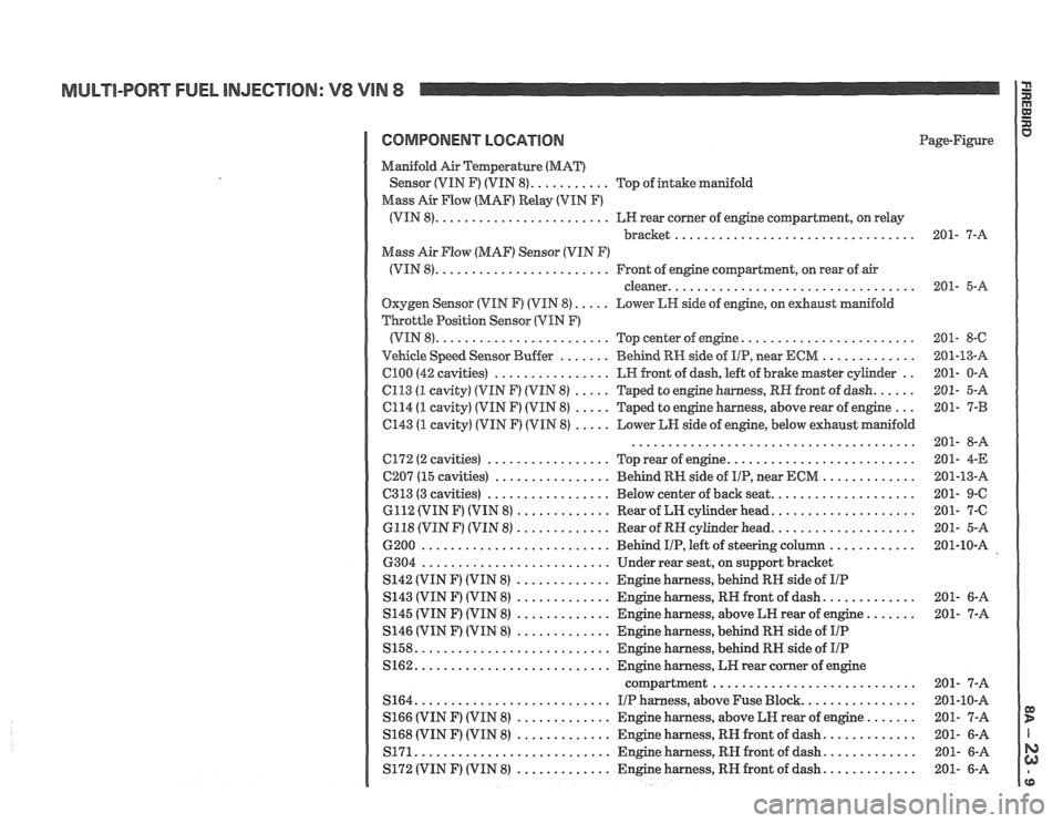
MULTI-PQRT FUEL INJECTION: V8 VIN 8
COMPONENT LOCATION Page-Figure
Manifold
Air amperatwe (MAT)
........... Sensor (VIN F) (VIN 8) Top of intake manifold
Mass
Air Flow (MAF) Relay (VIN F)
........................ (VIN 8) LH rear corner of engine compartment. on relay
bracket
.................................
Mass Air Flow (MAF) Sensor (VIN F)
........................ (VIN 8) Front of engine coqartment. on rear of air
.................................. cleaner
Oxygen Sensor (VIN F) (VIN 8) ..... Lower LW side of engine. on exhaust manifold
Throttle Position Sensor (VIN
F)
........................ (VIN 8)
Top center of engine ........................
....... ............. Vehicle Speed Sensor Buffer BeGnd RH side of IIP. near ECM
................ C100 (42 cavities) LH front of dash. left of brake master cylinder ..
6113 (1 cavity) (VIN F) (VIM 8) ..... Taped to engine harness. RH front of dash ......
C114 (1 cavity) (VIN F) (VIN 8) ..... Taped to engine harness. above rear of engine ...
C143 (1 cavity) (VIN F) (VIN 8) ..... Lower LH side of engine. below exhaust manifold
.......................................
.......................... ................. C172 (2 cavities)
Top rear of engine
................ C207 (15 cavities)
Behind RI-I side of IIP. near ECM .............
................. .................... C313 (3 cavities) Below center of back seat
............. GI12 (VIN F) (VIN 8)
Rear of LN cylinder head ....................
............. .................... 6118 (VIN F) (VIN 8) Rear of RH cylinder head
.......................... 6200
Behind IIP. left of steering column ............
.......................... 6304
Under rear seat. on support bracket
............. S142 (VIN F) (VIN 8)
Engine harness. behind RH side of IIP
............. ............. S143 (VIN F) (VIN 8) Engine harness. RH front of dash
............. S145 (VIN F) (VIN 8)
Engine harness. above LH rear of engine .......
............. S146 (VIN F) (VIN 8)
Engine harness. behind RH side of IIP
........................... S158
Engine harness. behind RN side of IIP
........................... S162 Engine harness. LK rear corner of engine
compartment
............................
........................... S164 I/P harness. above Fuse Block ................
............. S166 (VIN F) (VIN 8) Engine harness.
above LN rear of engine .......
............. ............. S168 (VIN F) (VIN 8) Engine harness. RH front
of dash
........................... ............. S171 Engine harness. RN front of dash
1 S172 (VIN F) (VIN 8) ............. ~n& harness. RH front of dash .............
Page 1309 of 1825
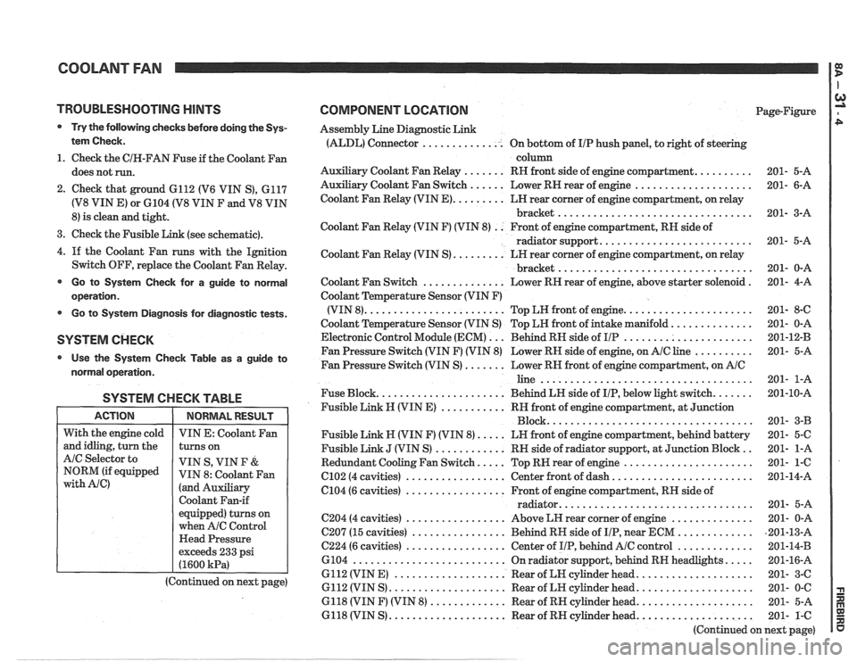
COOLANT FAN I g
TROUBLESHOOTING HINTS
@ Try the following checks before doing the Sys-
tem Check.
1. Check the CIH-FAN Fuse if the Coolant Fan
does not run.
2. Check that ground 6112 (V6 VIN S), 6117
(V8 VIN E) or 6104 (V8 VIN F and V8 VIN
8) is clean and tight.
3. Check the Fusible Link (see schematic).
4.
If the Coolant Fan runs with the Ignition
Switch OFF, replace the Coolant Fan Relay.
@ Go to System Check for a guide to normal
operation.
Go to System Diagnosis for diagnostic tests.
SYSTEM CHECK
Use the System Checlc Table as a guide to
normal operation.
SYSTEM CHECK TABLE
I ACTION I NORMALRESULT 1
COMPONENT LOCATION Page-Figure
Assembly Line Diagnostic Link
(ALDL) Connector .............. On bottom of IIP hush panel, to right of steering
column
Auxiliary Coolant Fan Relay
....... RH front side of engine compartment. ......... 201- 5-A
Auxiliary Coolant Fan Switch
...... Lower RN rear of engine .................... 201- 6-A
Coolant Fan Relay (VIN
E). ........ LH rear corner of engine compartment, on relay
bracket
................................. 201- 3-A
Coolant Fan Relay (VIN F) (VIN 8)
. . Front of engine compartment, RN side of
radiator support.
......................... 201- 5-A
Coolant Fan Relay (VIN S)
......... LH rear corner of engine compartment, on relay
................................. bracket 201- 0-A
Coolant Fan Switch
.............. Lower RH rear of engine, above starter solenoid . 201- 4-A
Coolant Temperature Sensor (VIN F)
(VIN 8).
....................... Top LW front of engine. ..................... 201- 8-C
Coolant Temperature Sensor (VIN S) Top LH front of intake manifold.
............. 201- 0-A
Electronic Control Module (ECM)
... Behind RN side of IIP ...................... 201-12-B
Fan Pressure Switch (VIN F) (VIN 8) Lower RH side of engine, on
AIC line .......... 201- 5-A
Fan Pressure Switch (VIN S)
....... Lower RN front of engine compartment, on AIC
line .................................... 201- 1-A
Fuse Block.
..................... Behind LN side of IIP, below light switch. ...... 201-10-A
Fusible Link
N (VIN E) ........... RH front of engine compartment, at Junction
Block ................................... 201- 3-B
Fusible Link N (VIN F) (VIN 8).
.... LN front of engine compartment, behind battery 201- 5-C
Fusible Link
J (VIN S) ............ RN side of radiator support, at Junction Block .. 201- 1-A
Redundant Cooling Fan Switch.
.... Top RW rear of engine ...................... 201- 1-6
C102 (4 cavities) ................. Center front of dash. ....................... 201-14-A
6104 (6 cavities)
................. Front of engine compartment, RH side of
................................ radiator. 201- 5-A
C204 (4 cavities) ................. Above LH rear corner of engine .............. 201- 0-A
C207 (15 cavities)
................ Behind RH side of IIP, near ECM ............. ,201-13-A
C224 (6 cavities) ................. Center of IIP, behind AIC control ............. 201-14-B
6104
.......................... On radiator support, behind RN headlights. .... 201-16-A
6112 (VIN E)
................... Rear of LN cylinder head. ................... 201- 3-C
6112 (VIN S)
.................... Rear of LH cylinder head. ................... 201- 0-C
6118 (VIN F) (VIN 8)
............. Rear of RH cylinder head. ................... 201- 5-A
6118 (VIN S)
.................... Rear of RH cylinder head. ................... 201- 1-C
(Continued on next page)
With
the engine cold
and idling, turn the
AIC Selector to
NORM (if equipped
with Ale)
VIN E: Coolant Fan
turns on
VIN S, VIN
F &
VIN 8: Coolant Fan
(and Auxiliary
Coolant Fan-if
equipped) turns on
when
A/C Control
Head Pressure
exceeds 233 psi
(1600
kPa)
(Continued on next page)
Page 1315 of 1825
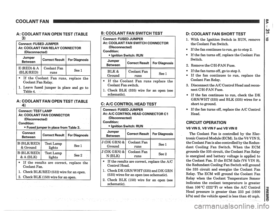
COOLANT FAN I $
A: COOLANT FAN OPEN TEST (TABLE
3)
Connect: FUSED JUMPER
At: COOLANT FAN RELAY CONNECTOR
(Disconnected)
Jumper Correct Result For Diagnosis
Between
1. Leave fused jumper in place and go to
Table
4.
E (RED) & A
(BLKIRED)
A: COOLANT FAN OPEN TEST (TABLE
41
Connect: TEST LAMP
At: COOLANT FAN CONNECTOR
(Disconnected)
Condition:
Fused jumper in place from Table
3.
If the Coolant Fan runs, replace the
Coolant Fan Relay. Coolant
Fan
runs
-. -. See --
B: COOLANT FAN SWITCH TEST
Connect
Between
B (BLKtRED)
& Ground
B (BLKIRED)
& A (BLK)
Connect: FUSED JUlVlPER
At: COOLANT FAN SWITCH CONNECTOR
(Disconnected)
Condition: lgnition Switch: RUN
Jumper
Between Correct
Result For Diagnosis
Coolant Fan
Ground
runs
If the Coolant Fan runs replace the
Coolant Fan switch.
1. Check BLK (335) wire for an open (see
schematic).
6: AIC CONTROL HEAD TEST
If the results are correct, replace the
Coolant Fan.
1. Check BLKIRED (532) wire for an open.
2. Check BLK (150) wire for an open.
Correct Result
Test Lamp
lights
Test Lamp
lights
Connect: FUSED JUMPER
At:
A/C CONTROL HEAD CONNECTOR Cl
(Disconnected)
Condition:
lgnition Switch: RUN
For Diagnosis
See 1
See 2
Jumper
Between I Correct Result I For Diagnosis I
".' Ground
J (DK GRN) & Coolant Fan See N (BLK) runs
If the results are correct, replace the
AIC
Control Head.
1. Check DK GRNIWHT (335) and DK GRN
(535) wires for an open (see schematic).
2. Check BLK (150) wire for an open (see
schematic).
D: COOLANT FAN SHORT TEST
1. With the Ignition Switch in RUN, remove
the Coolant Fan Switch.
If the fan continues to
run, go to step 2.
If the fan turns off, replace the Coolant Fan
Switch.
2. Remove the CIH-FAN Fuse.
If the fan turns off, go to step 3.
If the fan continues to run, replace the
Coolant Fan Relay.
3. Disconnect the
AIC Control Head and recon-
nect CIH-FAN Fuse.
If the fan continues to run,
check the DK
GRNIWHT (335) and BLK (335) wires for a
short to ground.
If the fan turns off, replace the
AIC Control
Head.
CIRCUIT OPERATION
V6 VIN S, V8 VIN F and V8 VIN 8
The Coolant Fan is controlled by the Elec-
tronic Control Module (ECM). In the V6 VIN S,
the Coolant Fan is also controlled by the Redun-
dant Cooling Fan Switch. When the ECM
grounds the 335 circuit, the Coolant Fan Relay
is energized and battery voltage is applied to
the Coolant Fan.
If the ECM fails (V6 VIN S),
the Redundant Cooling Fan Switch will ground
the 335 circuit and energize the Coolant Fan
Relay. The ECM will ground the Coolant Fan
Relay when the Coolant Temperature Sensor
indicates the coolant temperature is greater
than 106
OC (222 OF) or when the AIC Control
Head pressure is greater than 233 psi (1600
kPa) and the vehicle speed is less than 40 mph.
Page 1317 of 1825
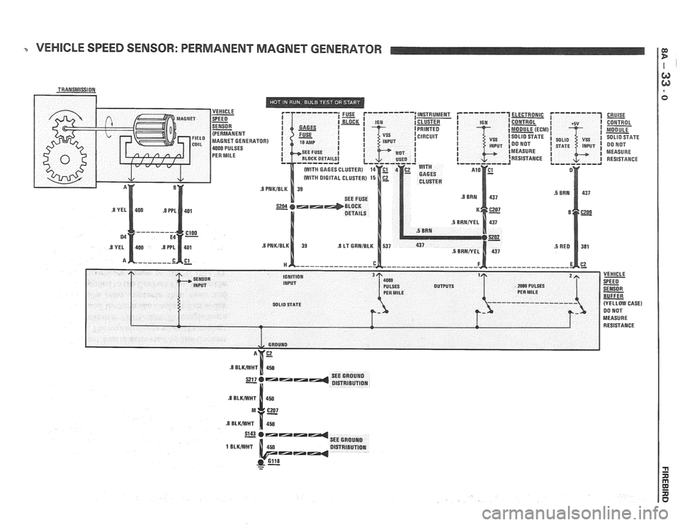
VEHICLE SPEED SENSOR: PERMANENT MAGNET GENERATOR
ELECTRONIC
CONTROL
MODULE (ECM
SOLID STATE
DO NOT
MEASURE RESISTANCE CRUISE
- CONTROL
MODULE
SOLID SFATE DO NOT
MEASURE RESISTANCE