sensor PONTIAC FIERO 1988 Service Repair Manual
[x] Cancel search | Manufacturer: PONTIAC, Model Year: 1988, Model line: FIERO, Model: PONTIAC FIERO 1988Pages: 1825, PDF Size: 99.44 MB
Page 1318 of 1825
VEHICLE SPEED SENSOR
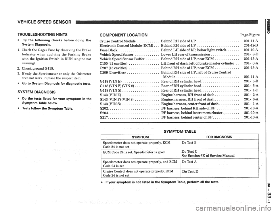
TROUBLESHOOTING HINTS
0 Try the following checks before doing the
System Diagnosis
.
1
. Check the Gages Fuse by observing the Brake
Indicator when applying the Parking Brake
wrth the Ignition Switch in RUN (engine not
running)
.
2 . Check ground 6118 .
3 . If only the Speedometer or only the Odometer
does not work. replace the suspect item
.
Go to System Diagnosis for diagnostic tests .
SYSTEM DlAGNOSlS
Do the tests listed for your symptom in the
Symptom Table below
.
Tests follow the Syrnptom Table .
COMPONENT LOCATION Page-Figure
Cruise Control Module
............ Behind RN side of IlP ...................... 201-11-A
Electronic Control Module (ECM)
... Behind RN side of IIP ...................... 201-12-B
Fuse Block
...................... Behind LN side of IIP. below light switch ....... 201-10-A
Vehicle Speed Sensor
............. Lower LEI rear of transmission ............... 201- 8-D
Vehicle Speed Sensor Buffer
....... Behind RH side of IIP. near ECM ............. 201-13-A
ClOO (42 cavities) ................ LN front of dash. left of brake master cylinder .. 201- 0-A
C207 (15 cavities) ................ Behind RH side of IIP. near ECM ............. 201-13-A
C209 (2 cavities)
................. Behind RN side of IIP. left of Cruise Control
................................. Module 201-11-A
6118 (VIN E)
................... Rear of RH cylinder head .................... 201- 5-B
6118 (VIN F) (VIN 8) ............. Rear of RN cylinder head .................... 201- 5-A
6118 (VIN S)
.................... Rear of RN cylinder head .................... 201- 1-C
S143 (VINE)
.................... Engine harness. RH front of dash ............. 201- 2-A
S143 (VIN F) (VIN
8) ............. Engine harness. RN front of dash ............. 201- 6-A
S143 (VIN S)
.................... Engine harness. center front of dash ........... 201- 1-A
S202
........................... IIP harness. behind RH side of IIP ............ 201-13-A
S204
........................... IIP harness. behind instrument cluster ......... 201-10-A
S217 ........................... IIP harness. behind center of IIP .............. 201-10-A
SYMPTOM TABLE
I SYMPTOM I FOR DIAGNOSIS I
=liter does not operate properly. ECM I Do Test B
code 24 is not set
ECM Code
24 is set. Speedometer is good
e If your symptom is not listed in the Symptom Table. pedorm all the tests .
Do Test C
See Section 6E of Service Manual
Speedometer does not operate properly. and ECM
Code
24 is set
Cruise Control does not operate properly. ECM
Code
24 is not set Do
Test
A
Do Test D
Page 1319 of 1825
VEHICLE SPEED SENSOR
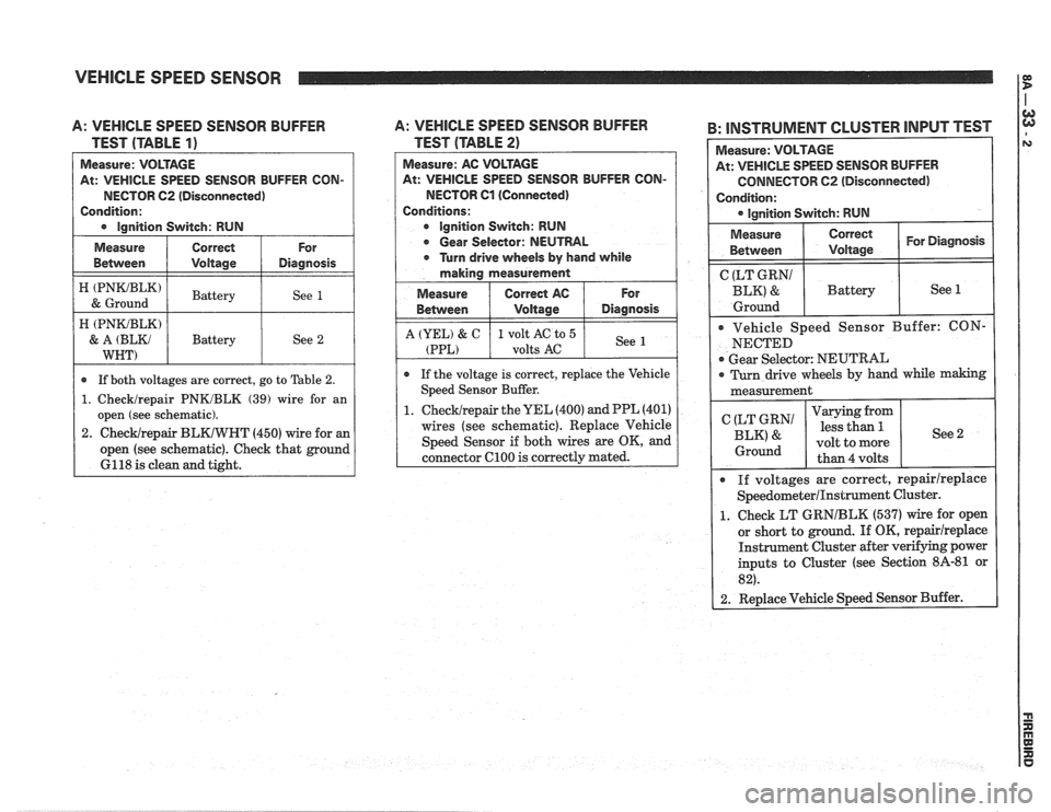
A: VEHICLE SPEED SENSOR BUFFER
TEST (TABLE
1)
At: VEHICLE SPEED SENSOR BUFFER CON-
NECTOR
62 (Disconnected)
Condition:
I e lnnition Switch: RUN I
I ztmz) I Battery I See 1 /
Measure
Between
A: VEHICLE SPEED SENSOR BUFFER
TEST (TABLE
2)
Measure: AC VOLTAGE
At: VEHICLE SPEED SENSOR BUFFER CON-
NECTOR Cl (Connected)
Conditions:
e Ignition Switch: RUN
e Gear Selector: NEUTRAL
e Turn drive wheels by hand while
making measurement
Measure
I Correct AC 1 For
Correct
Voltage
H (PNKJBLK)
& A (BLKJ
WNT)
B: INSTRUMENT CLUSTER INPUT TEST I
For
Diagnosis Measure:
VOLTAGE
At: VEHICLE SPEED SENSOR BUFFER
CONNECTOR C2 (Disconnected)
Condition: lgnition Switch: RUN
* If both voltages are correct, go to Table 2.
1. Checklrepair PNKJBLK (39) wire for an
open (see schematic).
2.
ChecWrepair BLKIWHT (450) wire for an
open (see schematic). Check that ground
6118 is clean and tight. Battery
See
2
Measure
Between Correct I For Diagnosis I I Voltage
Between
A (YEL) & C
(PPL)
( CgEg?' I Battery I See 1
e If the voltage is correct, replace the Vehicle
Speed Sensor Buffer.
1.
ChecWrepair the UEL (400) and PPL (401)
wires (see schematic). Replace Vehicle
Speed Sensor if both wires are OK, and
connector
C100 is correctly mated.
Voltage
1 volt AC to 5
volts
AC
Ground I
Vehicle Speed Sensor Buffer: CON-
NECTED
Gear Selector: NEUTRAL
Diagnosis
See
I 0 Turn drive wheels by hand while making I
measurement
I
If voltages are correct, repairlreplace
SpeedometerIInstrument Cluster.
1. Check LT GRNIBLK (537) wire for open
or short to ground. If OK,
repairireplace
Instrument Cluster after verifying power
inputs to Cluster (see Section
8A-81 or
82).
2. Replace Vehicle Speed Sensor Buffer.
(LT GRN1
BLK' &
Ground
Varying from
less than
5.
volt to more
than 4 volts See 2
Page 1320 of 1825
VEHICLE SPEED SENSOR
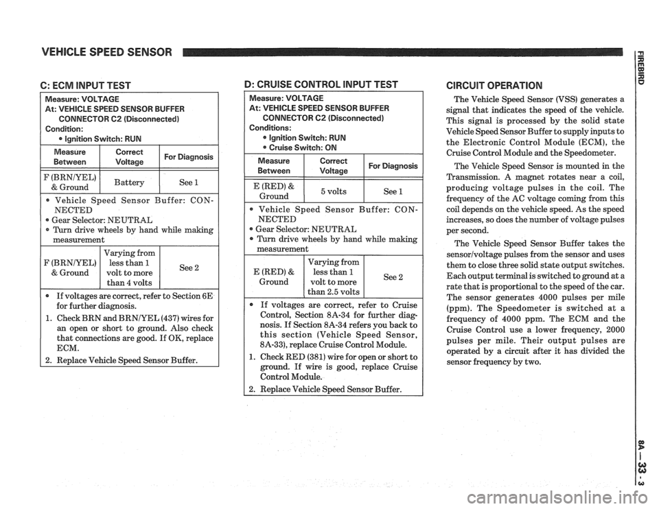
C: ECM INPUT TEST
At: VEHICLE SPEED SENSOR BUFFER
CONNECTOR
62 (Disconnected)
Gear Selector: NEUTRAL
1. Check BRN and
BRNIYEL (437) wires for
an open or short to ground. Also check
that connections are good. If
OK, replace
1 2. Replace Vehicle Speed Sensor Buffer.
At: VEHICLE SPEED SENSOR BUFFER
CONNECTOR
C2 (Disconnected)
Gear Selector: NEUTRAL
nosis. If Section 8A-34 refers you back to
this section (Vehicle Speed Sensor,
8A-33), replace Cruise Control Module.
1. Check RED (381) wire for open or short to
ground. If wire is good, replace Cruise
Control Module.
D: CRUISE CONTROL lNPUT TEST CIRCUIT OPERATION
The Vehicle Speed Sensor (VSS) generates a
signal that indicates the speed of the vehicle.
This signal is processed by the solid state
Vehicle Speed Sensor Buffer to supply inputs to
the Electronic Control Module (ECM), the
Cruise Control Module
and the Speedometer.
The Vehicle Speed Sensor is mounted in the
Transmission.
A magnet rotates near a coil,
producing voltage pulses in the coil. The
frequency of the AC voltage coming from this
coil depends on the vehicle speed. As the speed
increases, so does the number of voltage pulses
per second.
The Vehicle Speed Sensor Buffer takes the
sensorlvoltage pulses from the sensor and uses
them to close three solid state output switches.
Each output terminal is switched to ground at a
rate that is proportional to the speed of the car.
The sensor generates 4000 pulses per mile
(ppm). The Speedometer is switched at
a
frequency of 4000 ppm. The ECM and the
Cruise Control use a lower frequency, 2000
pulses per mile. Their output pulses are
operated by a circuit after it has divided the
sensor frequency by two.
Page 1322 of 1825
r--------------------------------------------------------------------------------------------------------------- I I IGNITION
I I I I SERVO I VACUUM I
I POSITION I
I SENSOR I INPUT I
CONNECTED
TO THROTTLE
Page 1323 of 1825
CRUISE CONTROL
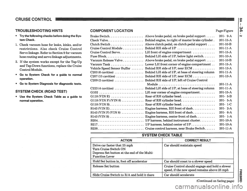
TROUBLESHOOTING HINTS
Try the following checks before doing the Sys-
tem Check
.
1 . Check vacuum hose for leaks. kinks. andlor
restrictions . Also check Cruise Control
Servo linkage
. Refer to Section 9 for vacuum
hose routing and servo linkage adjustments
.
2 . If the system works except for the Tap-Up
and
TapDown functions. replace the Cruise
Control Module
.
Go to System Check for a guide to normal
operation
.
Go to System Diagnosis for diagnostic tests .
SYSTEM CHECK (ROAD TEST)
Use the System Check Table as a guide to
normal operation
.
COMPONENT LOCATION Page-Figure
Brake Switch
.................... Above brake pedal. on brake pedal support ..... 201- 9-A
Check Valve
..................... Behind engine. to right of master brake cylinder . 201-15-A
Clutch Switch
................... Above clutch pedal. on clutch pedal support .... 201-10-B
Cruise Control Module
............ Behind RH side of IIP ...................... 201-11-A
Cruise Control Servo .............. LH front of engine compartment ............. 201-15-A
Fuse Block
...................... Behind LH side of IIP. below light switch ....... 201-10-A
Vacuum Release Valve
............ Above brake pedal. on brake pedal support ..... 201-10-B
Vacuum Tank ................... Lower LH front corner of engine compartment .. 201-15-A
Vehicle Speed Sensor Buffer
....... Behind RH side of IIP. near ECM ............. 201-13-A
C203 (6 cavities) ................. Behind LH side of IIP. at base of steering column 201-11-A
C207 (15 cavities) ................ Behind RH side of IIP. near ECM ............. 201-13-A
C209 (2 cavities) ................. Behind RH side of IIP. left of Cruise Control
................................. Module 201-11-A
C223 (4 cavities) ................. Behind LH side of IIP. at base of steering column 201-11-A
6102 .......................... LN rear corner of engine compartment ......... 201-15-A
6118 (VIN E)
................... Rear of RH cylinder head .................... 201- 5-B
6118 (VIN F) (VIN 8)
............. Rear of RN cylinder head .................... 201- 5-A
6118 (VIN S)
.................... Rear of RN cylinder head .................... 201- 1-C
S143 (VIN E) .................... Engine harness. RH front of dash ............. 201- 2-A
S143 (VIN
F) (VIN 8) ............. Engine harness. RN front of dash ............. 201- 6-A
S143 (VIN S)
.................... Engine harness. center front of dash ........... 201- 1-A
S204
........................... IIP harness. behind instrument cluster ......... 201-10-A
S217
........................... IIP harness. behind center of IIP .............. 201-10-A
S238
........................... Cruise control harness. near Brake Switch ...... 201-11-A
SYSTEM CHECK TABLE
Car should maintain speed
(Continued on facing page)
Page 1327 of 1825
CRUISE CONTROL
(Continued from previous page)
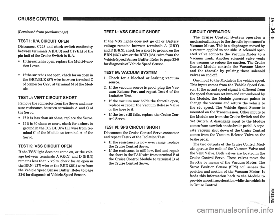
TEST I: RIA CIRCUIT OPEN
Disconnect C223 and check switch continuity
between terminals A (BLU) and C (YEL) of the
pin half of the Cruise Switch in RIA.
0 If the switch is open, replace the Multi-Func-
tion Lever.
If the switch is not open, check for an open in
the
GRYIBLK (87) wire between terminal C
of connector C223 at terminal M of the Mod-
ule.
TEST J: VENT CIRCUIT SHORT
Remove the connector from the Servo and mea-
sure resistance between terminals
A and C of
the Servo.
If it is less than 30 ohms, replace the Servo.
If it is 30 ohms or more, check for a short to
ground in the DK
BLUIWHT wire from ter-
minal C of the Module to terminal A of the
Servo.
TEST K: VSS ClRCUlT OPEN
If the VSS light does not come on, or the volt-
age between terminals A (GRY) and D (BRN)
remains less than 7 volts, check for an open in
the BRN (437) wire or the RED (381) wire from
the Vehicle Speed Sensor Buffer. Refer to page
33-0 for diagnosis of Vehicle Speed Sensor.
TEST L: VSS CIRCUIT SHORT
If the VSS lights does not go off or Battery
voltage remains between ter
and D
(BRN), check for a short to ground on the
BRN (437) wire or the RED (381) wire from the
Vehicle Speed Sensor Buffer. Refer to page 33-0
for diagnosis of Vehicle Speed Sensor.
TEST M: VACUUM SYSTEM
1. Check for a blocked or leaking vacuum
source.
2. If the vacuum source is good, plug the Vac-
uum Release Port and repeat Test
6 of the
Isolation Test.
If the vacuum now holds the throttle open,
replace or repair the Vacuum Release Valve
or the hose to it.
If the test still fails, replace the Cruise Con-
trol Servo.
TEST N: SPS CIRCUIT SHORT
Disconnect the Cruise Control Servo connector
and repeat Test 7 of the Isolation Test.
If the resistance is now over range, replace
the Cruise Control Servo.
If the resistance is still low, find and repair
the short in the TAN wire from terminal F of
the Cruise Control Module to terminal B of
the Cruise Control Servo.
ClRCUlT OPERATION
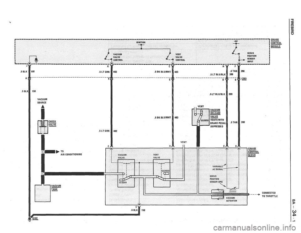
The Cruise Control System operates a
mechanical linkage to the throttle by means of a
Vacuum Motor. This is a diaphragm moved by
a vacuum applied to one side. A solenoid oper-
ated valve connects the Vacuum Motor to a
Vacuum Tank. Another solenoid valve vents
the vacuum to reduce the suction. The Cruise
Control Module controls the Vacuum Motor
and the throttle by pulsing these solenoid
valves on and off.
One input to the Module is the vehicle speed.
This input comes from the Vehicle Speed Sen-
sor. If the actual speed signal is different from
the speed that was set into and remembered by
the Module, the Module generates pulses to
change the vacuum and return the vehicle to
the set speed. The Vehicle Speed Sensor is
mounted on the Transmission. Other inputs to
the Module are from the Cruise Switch and the
Set Switch. A disengage input to the Module
comes from a switch on the brake pedal. A
sepe-
rate vacuum shut down of the Cruise Control
comes from the Vacuum Release Valve on the
brake pedal.
The two outputs of the Cruise Control Mod-
ule operate the coils of the Vacuum Valve and
the Vent Valve. Both valves are located in the
Cruise Control Servo. These valves move the
throttle be means of the Vacuum Motor. The
Servo Position Sensor
(SPS) coil senses the
position and motion of the Vacuum Motor. It
feeds this information back to the Module to
provide smooth acceleration while the vehicle is
in Cruise Control.
Page 1411 of 1825
(Continued from previous page)
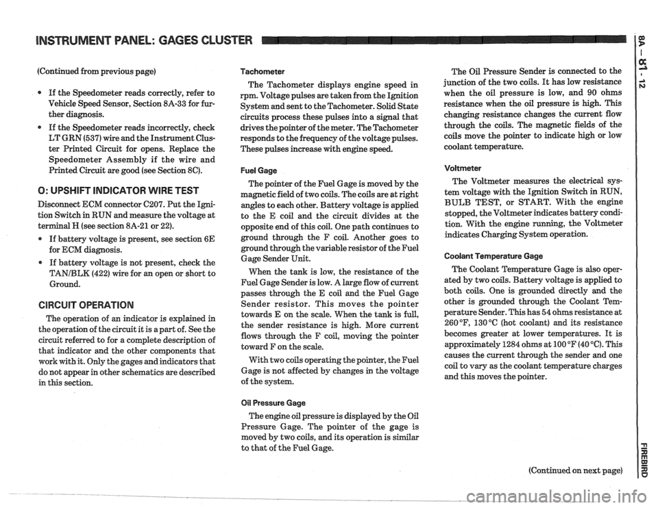
If the Speedometer reads correctly, refer to
Vehicle Speed Sensor, Section
8A-33 for fur-
ther diagnosis.
If the Speedometer reads incorrectly, check
LT GRN (537) wire and the Instrument Clus-
ter Printed Circuit for opens. Replace the
Speedometer Assembly if the wire and
Printed Circuit are good (see Section
8C).
O: UPSHIFT INDICATOR WIRE TEST
Disconnect ECM connector C207. Put the Igni-
tion Switch in RUN and measure the voltage at
terminal
H (see section 8A-21 or 22).
If battery voltage is present, see section
6E
for ECM diagnosis.
If battery voltage is not present, check the
TANIBLK (422) wire for an open or short to
Ground.
CIRCUIT OPERATION
The operation of an indicator is explained in
the operation of the circuit it is apart of. See the
circuit referred to for a complete description of
that indicator and the other components that
work with it. Only the gages and indicators that
do not appear in other schematics are described
in this section.
Tachometer
The Tachometer displays engine speed in
rpm. Voltage pulses are taken from the Ignition
System and sent to the Tachometer. Solid State
circuits process these pulses into a signal that
drives the pointer of the meter. The Tachometer
responds to the frequency of the voltage pulses.
These pulses increase with engine speed.
Fuel Gage
The pointer of the Fuel Gage is moved by the
magnetic field of two coils. The coils are at right
angles to each other. Battery voltage is applied
to the E coil and the circuit divides at the
opposite end of this coil. One path continues to
ground through the F coil. Another goes to
ground through the variable resistor of the Fuel
Gage Sender Unit.
When the tank is low, the resistance of the
Fuel Gage Sender is low. A large flow of current
passes through the E coil and the Fuel Gage
Sender resistor. This moves the pointer
towards E on the scale. When the tank is
full,
the sender resistance is high. More current
flows through the F coil, moving the pointer
toward F on the scale.
With two coils operating the pointer, the Fuel
Gage is not affected by changes in the voltage
of the system.
011 Pressure Gage
The engine oil pressure is displayed by the Oil
Pressure Gage. The pointer of the gage is
moved by two coils, and its operation is similar
to that of the Fuel Gage. The
Oil Pressure Sender is connected to the
junction of the two coils.
It has low resistance
when the oil pressure is low, and 90 ohms
resistance when the oil pressure is high. This
changing resistance changes the current flow
through the coils. The magnetic fields of the
coils move the pointer to indicate high or low
coolant temperature.
Voltmeter
The Voltmeter measures the electrical sys-
tem voltage with the Ignition Switch in RUN,
BULB TEST, or START. With the engine
stopped, the Voltmeter indicates battery condi-
tion. With the engine
running, the Voltmeter
indicates Charging System operation.
Coolant Temperature Gage
The Coolant Temperature Gage is also oper-
ated by two coils. Battery voltage is applied to
both coils. One is grounded directly
and the
other is grounded through the Coolant Tem-
perature Sender. This has 54 ohms resistance at
260
OF, 130 "C (hot coolant) and its resistance
becomes greater at lower temperatures. It is
appr~ximately 1284 ohms at 100 OF (40 '6). This
causes the current through the sender and one
coil to vary as the coolant temperature charges
and this moves the pointer.
Page 1412 of 1825
INSTRUMENT PANEL: GAGES CLUSTER
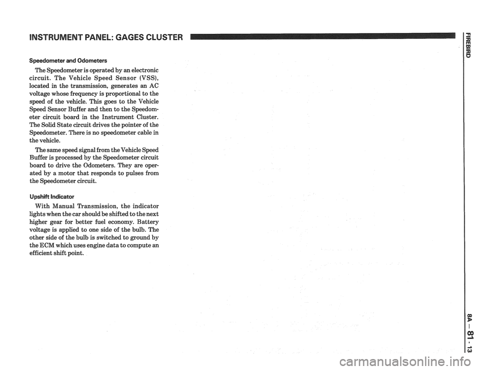
Speedorneter and Odometers
The Speedometer is operated by an electronic
circuit. The Vehicle Speed Sensor (VSS),
located in the transmission, generates an AC
voltage whose frequency is proportional to the
speed of the vehicle. This goes to the Vehicle
Speed Sensor Buffer and then to the Speedom-
eter circuit board in the Instrument Cluster.
The Solid State circuit drives the pointer of the
Speedometer. There is no speedometer cable
in
the vehicle.
The same speed signal from the Vehicle Speed
Buffer is processed by the Speedometer circuit
board to drive the Odometers. They are oper-
ated by a motor that responds to pulses from
the Speedometer circuit.
UpshiN Indicator
With Manual Transmission, the indicator
lights when the car should be shifted to the next
higher gear for better fuel economy. Battery
voltage is applied to one side of the bulb. The
other side of the bulb is switched to ground by
the ECM which uses engine data to compute an
efficient shift point.
Page 1416 of 1825
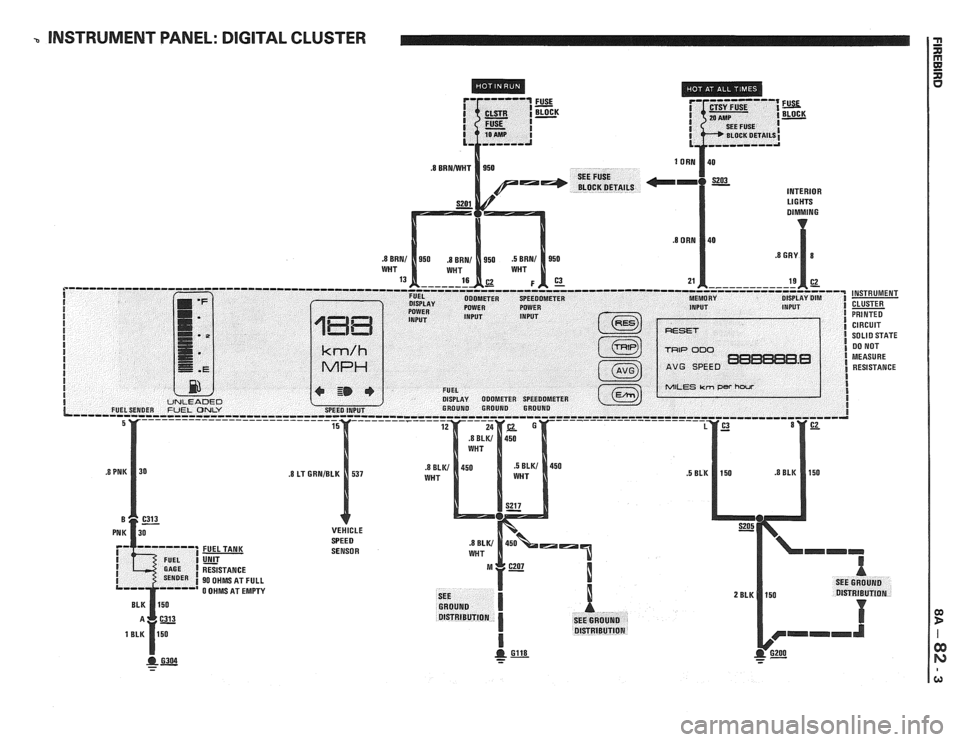
b INSTRUMENT PANEL: DIGITAL CLUSTER
INTERIOR Ll G HTS
SENSOR
- - -
Page 1427 of 1825
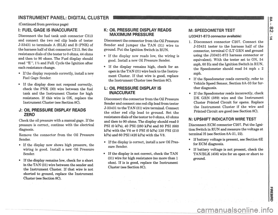
BNS'TWUMENT PANEL: DIGITAL CLUSTER a B
(Continued from previous gage)
I: FUEL GAGE IS INACCUWTE
Disconnect the fuel tank unit connector C313
and connect the two red clip leads of tester
5-33431 to
terminals A (BLK) and B (PNK) of
the harness half of that connector
C313. Set the
resistance
dials of the tester to 0 ohms, 44 ohms
and then to 90 ohms. The Fuel display should
read
"E ", 11/2 and Full. Cycle the Ignition after
each resistance change.
If the display responds correctly, install a new
Fuel Gage Sender.
If the display does not respond correctly,
check the PNK (30) wire between the fuel
tank and the Instrument Cluster for high
resistance.
If this wire is OK, replace the
Instrument Cluster (see Section
8C).
J: OIL PRESSURE DISIDWY READS
ZERO
Check the oil pressure with a manual gage. If the
pressure is correct, continue with the electrical
diagnosis.
Remove the connector from the Oil Pressure
Sender.
If the display now shows high pressure, the
wiring is good. Install a new Oil Pressure
Sender.
If the display remains low, check for a short
in the TAN (31)
wire between the sender and
the Instrument Cluster. If that wire is not
shorted to ground, replace the Instrument
Cluster (see Section
8C).
K: OIL PRESSURE DISPWY RWDS
MMlMklM PRESSURE
Disconnect the connector from the Oil Pressure
Sender and jumper the TAN (31) wire to
ground. Put the Ignition Switch in RUN.
If the display now reads low, the wiring is
good. Install a new
Oil Pressure Sender.
* If the display remains high, check for an
open in the TAN (31) wire back to the Instru-
ment Cluster. If that wire is good, replace
the Instrument Cluster (see Section
8C).
L: OIL PRESSURE BlSPLAV IS
llUAGCll RATE
Disconnect the connector from the Oil Pressure
Sender and connect one red clip lead from tester
5-3343
1 to the TAN (3 1) wire terminal. Connect
the other red clip lead to ground. Set the
resistance dials of the
testor to 0 ohms, 43 ohms
and then to 90 ohms. The display should read 0
PSI (0
kPa), 40 PSI (280 kPa) and 80 PSI (660
kPa) with the V6 or 0 PSI (0 kPa) 130 PSI (210
kPa) and 60 PSI (420 kPa) with the V8.
r If the display is correct, install a new Oil Pres-
sure Sender.
If the display is not correct, check the TAN
(31) wire for high resistance (no more than
1
ohm). If is is good, replace the Instrument
Cluster (see Section
8C).
M: SPEEDOMETER BEST
(533431 -873 conneetor available)
1. Disconnect connector C207. Connect the
5-33431 tester to the harness
half of the
connector, terminal
C (LT GRN and ground
using the
533431-873 harness connector or
equivalent). With the tester set to
ON, 54
mph, 60
Hz and the Ignition Switch in RUN,
the Speedometer should read 54
qh + 2
mph.
If the Speedometer reads correctly, refer to
Vehicle Speed Sensor, Section
8A-33 for fur-
ther diagnosis.
If the Speedometer reads incorrectly, check
DK GRN (389) wire and the Instrument
Cluster Printed Circuit for opens. Replace
the Instrument Cluster if the wire and
Printed Circuit are good (see Section
8C).
N: UPSHIFT lNDlCATOR WIRE TEST
Disconnect ECM connector C207. Put the Igni-
tion Switch
in RUN and measure the voltage at
terminal
N (see Section 8A-21,221.
If battery voltage is present, see Section 6E
for ECM diagnosis.
If battery voltage is not present, check the
TANIBLK (456) wire for an open or short to
ground.