PONTIAC FIERO 1988 Service Repair Manual
Manufacturer: PONTIAC, Model Year: 1988, Model line: FIERO, Model: PONTIAC FIERO 1988Pages: 1825, PDF Size: 99.44 MB
Page 591 of 1825
6E2-CZ-16 DRIVEABILITY AND EMISSIONS - 5.OL (WIN E)
CHART C-2C
IDLE AIR CONTROL (IAC) VALVE CHECK
5.OL (VIN E) "F'" SERIES (TBI)
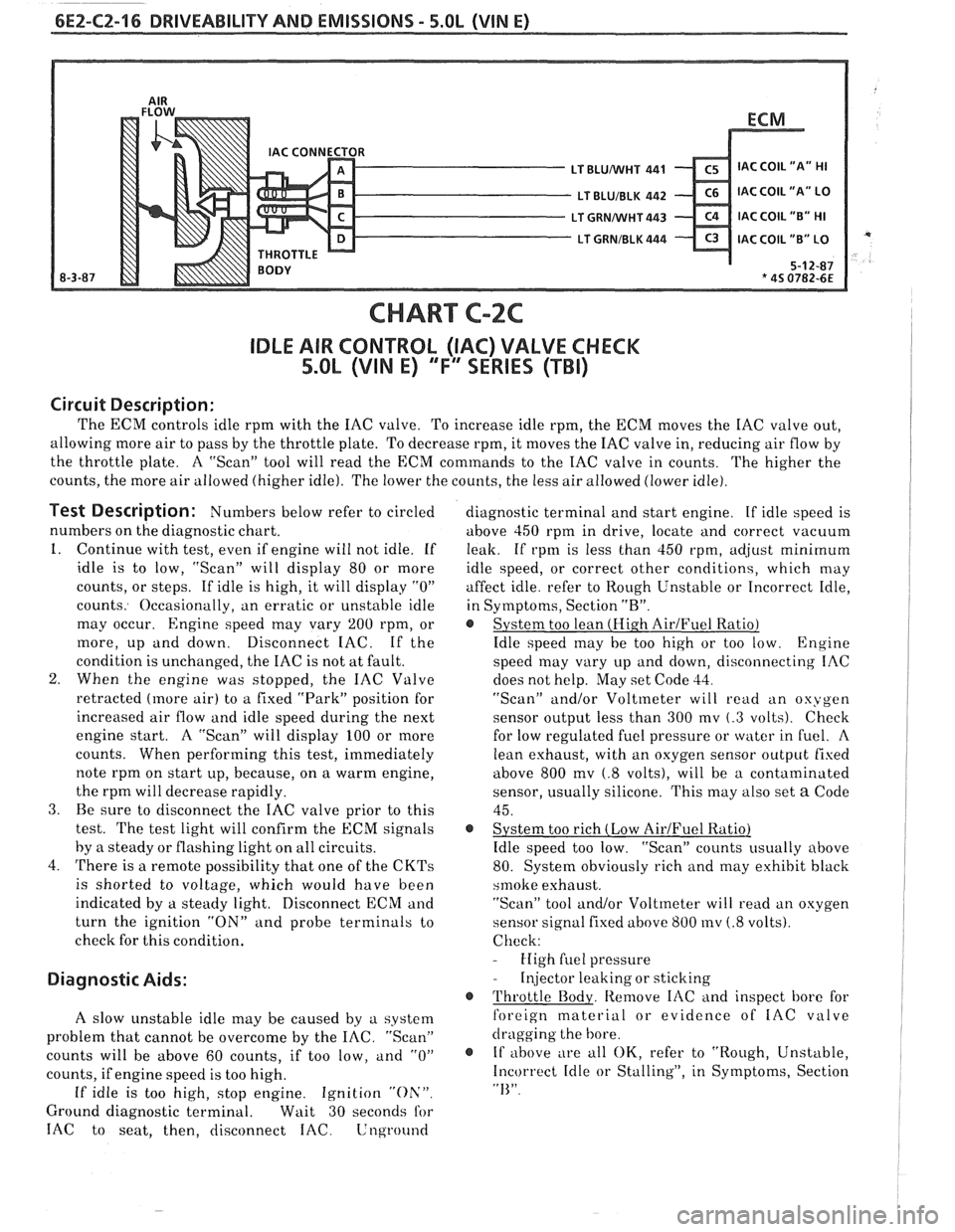
Circuit Description:
The ECM controls idle rprn with the IAC valve. To increase idle rpm, the ECM moves the IAC valve out,
allowing more air to pass by the throttle plate. To decrease rpm, it moves the IAC valve in, reducing air flow by
the throttle plate. A "Scan" tool will read the
ECM commands to the IAC valve in counts.
The higher the
counts, the more air allowed (higher idle). The lower the counts, the less air allowed (lower idle).
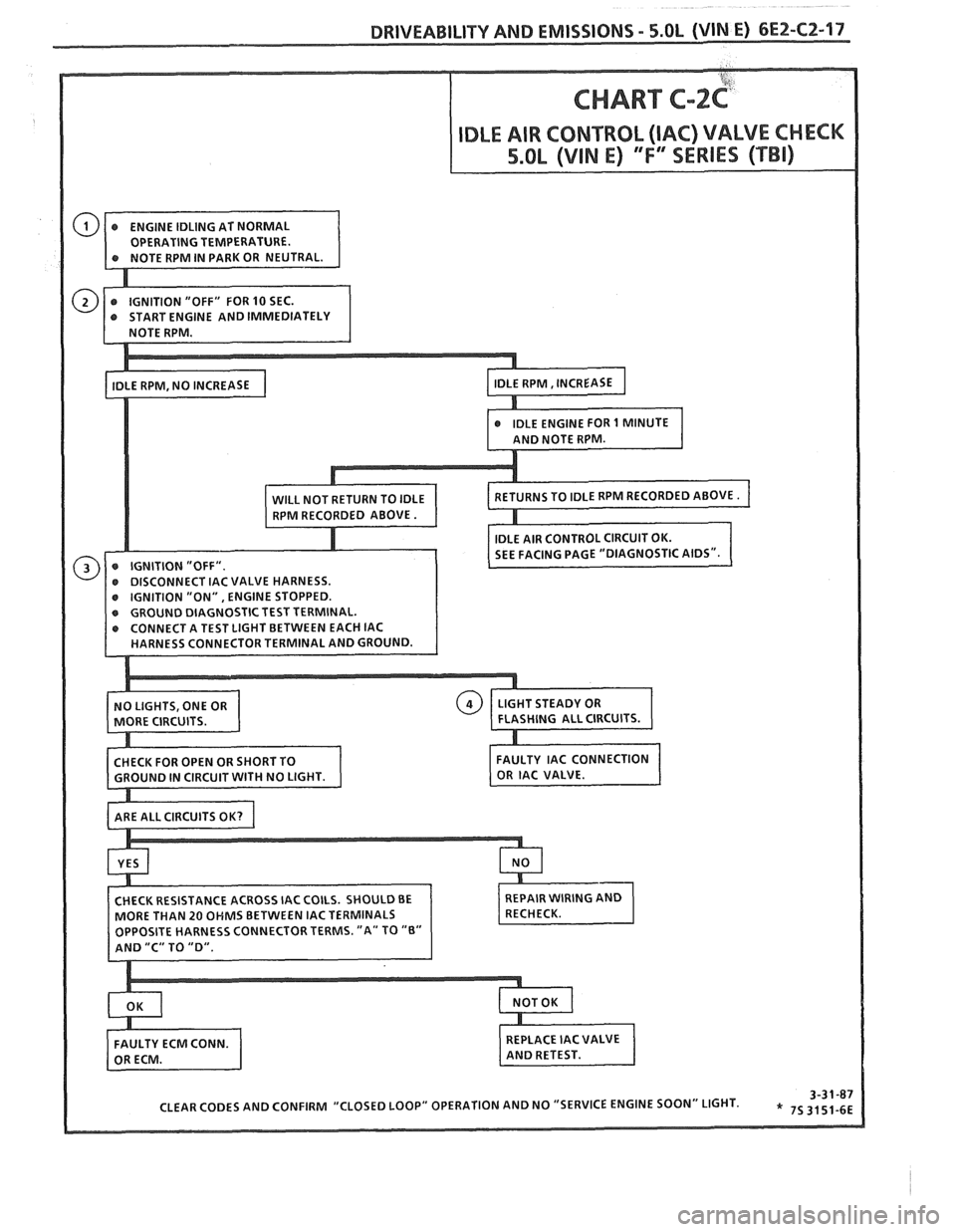
Test Description: Numbers below refer to circled
numbers on the diagnostic chart.
1. Continue with test, even if engine will not idle. If
idle is to low, "Scan" will display 80 or more
counts, or steps. If idle is high, it will display
"0"
counts. Occasionally, an erratic or unstable idle
may occur.
Engine speed may vary 200 rpm, or
more, up and down. Disconnect IAC. If the
condition is unchanged, the IAC is not at fault.
2. When the engine was stopped, the IAC Valve
retracted (more air) to a fixed "Park" position for
increased air flow and idle speed during the next
engine start. A "Scan" will display 100 or more
counts. When performing this test, immediately
note rprn on start up, because, on a warm engine,
the rprn will decrease rapidly.
3. Be sure to disconnect the IAC valve prior to this
test.
The test light will confirm the ECM signals
by
a steady or flashing light on all circuits.
4. There is a remote possibility that one of the
CKTs
is shorted to voltage, which would have been
indicated by a steady light. Disconnect ECM and
turn the ignition
"ON" and probe terminals to
check for this condition.
Diagnostic Aids:
A slow unstable idle may be caused by a system
problem that cannot be overcome by the
IAC. "Scan"
counts will be above 60 counts, if too low,
and "0"
counts, if engine speed is too high.
If idle is too high, stop engine. Ignition "Oh'".
Ground diagnostic terminal. Wait 30 seconds for
IAC to seat, then, disconnect IAC. Lnground
diagnostic terminal and start engine. If idle speed is
above 450 rprn in drive, locate and correct vacuum
leak. If rpm is less than 450 rpm,
ad,jrlst minimum
idle speed, or correct other conditions, which may
affect idle. refer to Rough Unstable or Incorrect Idle,
in Symptoms, Section
"R".
@ System too lean (Hi.gh AirJFuel Ratio)
Idle speed may be too high or too low. Engine
speed may vary up and down, disconnecting IAC
does not help. May set Code
33.
"Scan" and/or Voltmeter will read an oxygen
sensor output less than 300 mv
(.3 volts). Check
for low regulated fuel pressure or water in
fuel. A
lean exhaust, with an oxygen sensor outpirt fixed
above 800
mv (.8 volts), will be a contaminated
sensor, usually silicone. This may also set
a Code
45.
@ System too rich (Low AirIFuel Ratio)
Idle speed too low. "Scan" counts usually above
80. System obviously rich and may exhibit black
srnoke exhaust.
"Scan" tool and/or Voltmeter will
read an oxygen
sensor signal fixed above 800
mv (.8 volts).
Check:
- High fuel pressure
- Injector leaking or sticking
@ Throttle Body. Remove IAC and inspect bore for
foreign material or evidence of
IAC valve
dragging the bore.
@ If above ;
e all OK, refer to "Rough, Unstable,
Incorrect Idle or Stalling", in Symptoms, Section
"I<".
Page 592 of 1825
DRIVEABILITY AND EMISSIONS - 5.OL (VIN E) 6E2-C2-17
ST TERMINAL.
ETWEEN EACH IAC
Page 593 of 1825

6E2-CZ-18 DRIVEABILITY AND EMISSIONS - 5.OL (VIN E)
BLANK
Page 594 of 1825
DRIVEABILITY AND EMISSIONS 5.8L (VIN E) 6EZ-C3-1
SECTION C3
EVAPORATIVE EMISSION CONTROL SVSEENI (EECS)
CONTENTS
........................ GENERAL DESCRIPTION ............... C3-1 DIAGNOSIS C3-2
.......... PURPOSE ........................ C3-1 VISUAL CHECK OF CANISTER C3-2
.......... VAPOR CANISTER.. ................. C3-1 CANISTER PURGE SOLENOID C3-2
................. EVAPORATIVE EMISSION SYSTEM.. ..... C3-1 ON-CAR SERVICE C3-2
............ IN-TANK PRESSURE CONTROL VALVE . . C3-2 FUEL VAPOR CANISTER R/R C3-2
.................. RESULTS OF INCORRECT OPERATION .... C3-2 CANISTER HOSES.. C3-2
................ PARTS INFORMATION C3-2
GENERAL DESCRIPTION
PURPOSE
The basic evaporative emission control system
(EECS) used on all vehicles is the charcoal canister
storage method. This method transfers fuel vapor
from the fuel tank to an activated carbon (charcoal)
storage device (canister) to hold the vapors when the
vehicle is not operating. When the engine is running,
the fuel vapor is purged from the carbon element by
intake air flow and consumed in the normal
combustion process.
VAPOR CANISTER
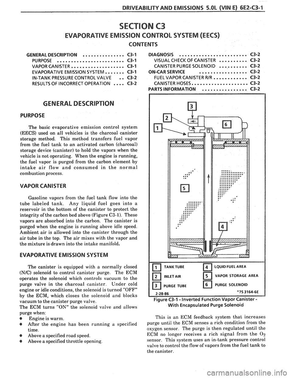
Gasoline vapors from the fuel tank flow into the
tube labeled tank. Any liquid
fuel goes into a
reservoir in the bottom of the canister to protect the
integrity of the carbon bed above (Figure C3-1). These
vapors are absorbed into the carbon. The canister is
purged when the engine is running above idle speed.
Ambient air is allowed into the canister through the
air tube in the top. The air mixes with the vapor and
the mixture is drawn into the intake manifold.
EVAPORATIVE EMISSION SYSTEM
The canister is equipped with a normally closed
(N/C) solenoid to control canister purge. The ECM
operates the solenoid which controls vacuum to the
purge valve in the charcoal canister. Under cold
engine or idle conditions, the solenoid is turned "OFF"
by the ECM, which closes the solenoid and blocks
vacuum to the canister purge valve.
The ECM turns "ON" the solenoid valve and allows
purge when:
@ Engine is warm.
@ After the engine has been running a specified
time.
@ Above a specified road speed.
@ Above a specified throttle opening.
TANKTUBE LQUID FUEL AREA
INLET AIR VAPOR STORAGE AREA
PURGE TUBE PURGE
SOLENOID
Figure C3-1 - Inverted Function Vapor Canister -
With Encapsulated Purge Solenoid
This is an ECM feedback system that increases
purge until the ECM senses a rich condition from the
oxygen sensor. The purge
is then regulated until the
ECM no longer receives a rich signal from the
O2
sensor. This system uses an in-tank pressure control
valve to control the flow of vapors from the fuel tank to
the canister.
Page 595 of 1825
ILIT'V AND EMISSIONS
IN-TANK PRESSURE CONTROL VALVE VISUAL
CHECK OF CANISTER
The in-tank pressure control valve, a combination
roll-over, integral pressure and vacuum relief valve, is
located with the fuel sending unit in the fuel tank.
When vapor pressure in the tank exceeds 1" Hg
(5
kPa! the valve opens and allows vapors to vent to the
canister and then be purged. When the tank pressure
drops below the opening point of the valve it will close,
keeping vapors in the fuel tank. The valve provides
vacuum relief to protect against vacuum build up in
the fuel tank and roll- over protection to prevent
liquid fuel from entering the canister during normal
driving maneuvers.
RESULTS OF INCORRECT OPERATION
Poor idle, stalling and poor driveability can be
caused by:
- Inoperative purge solenoid. Cracked or
damaged, replace canister.
ON-CAR SERVICE
FUEL VAPOR CANISTER
Remove or Disconnect
1. Hoses from canister. Mark hoses to install on
new canister.
2. Canister.
Install or Connect
1. Canister as removed
2. Hoses. Make sure connections are correct.
CANISTER HOSES
- Damaged canister.
- Hoses split, cracked and, or not connected to Refer to Vehicle
Emission Control Information
the proper tubes. Label for
routing of canister hoses.
~videnEe ;f fuel loss or fuel vapor odor can be
caused by: PARTS INFORMATION
- Liquid fuel leaking from fuel lines.
- Cracked or damaged canister. PART NAME GROUP
- Disconnected,
misrouted, kinked, deteriorated
or damaged vapor hoses, or control hoses. Canister, Fuel
Vapor . . . . . . . . . . . . . . . . . . 3.130
DIAGNOSIS
The canister purge solenoid operation is covered in
CHART C-3 at the end of this section.
A failure in the
solenoid or connections may result in a Code
26.
Page 596 of 1825
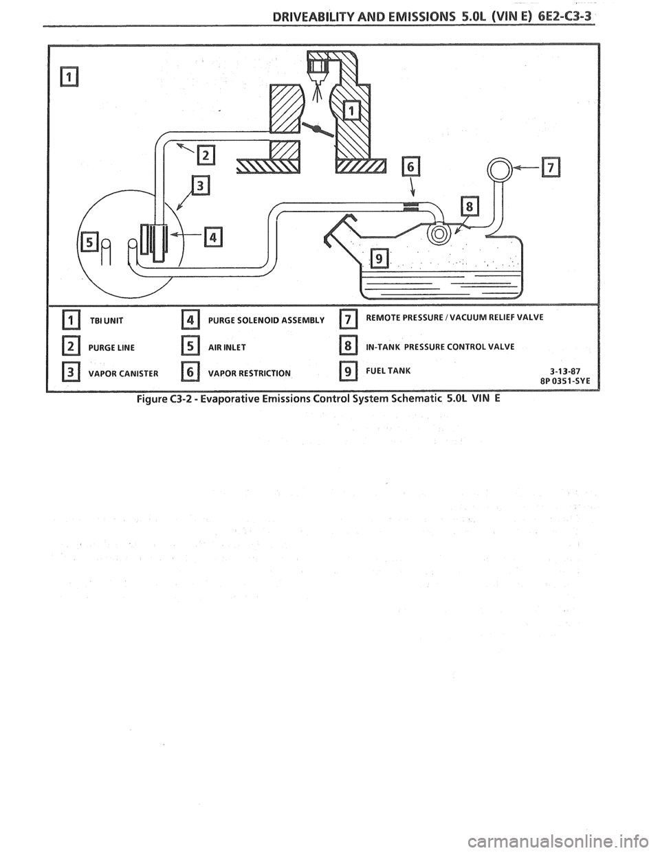
DRIVEABILITY AND EMISSIONS 5.OL (VIN E) 6E2-C3-3
PURGE SOLENOID ASSEMBLY
Figure C3-2 - Evaporative Emissions Control System Schematic 5.OL VIN E
Page 597 of 1825
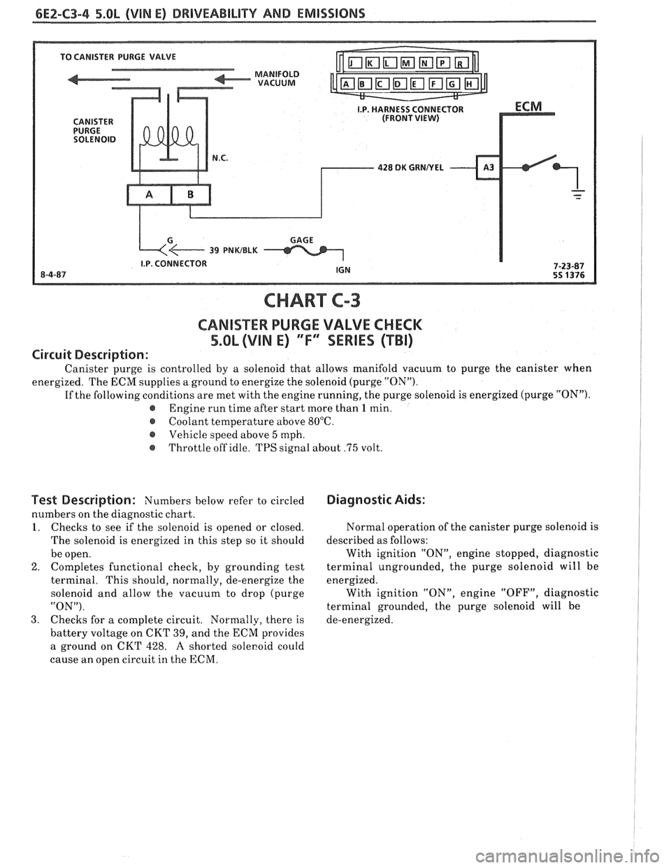
6E2-C3-4 5.OL (VIN E) DRIVEABILITY AND EMISSIONS
428 DK GRNNEL
CHART C-3
CANlSTER PURGE VALVE CHECK
5.OL (VIN E) "F"' SERlES (TBI)
Circuit Description:
Canister purge is controlled by a solenoid that allows manifold vacuum to purge the canister when
energized. The ECM supplies a ground to energize the solenoid (purge "ON").
If the following conditions are met with the engine running, the purge solenoid is energized (purge "ON").
@ Engine run time after start more than 1 min.
@ Coolant temperature above 80°C.
Vehicle speed above
5 mph.
@ Throttle off idle. TPS signal about .75 volt.
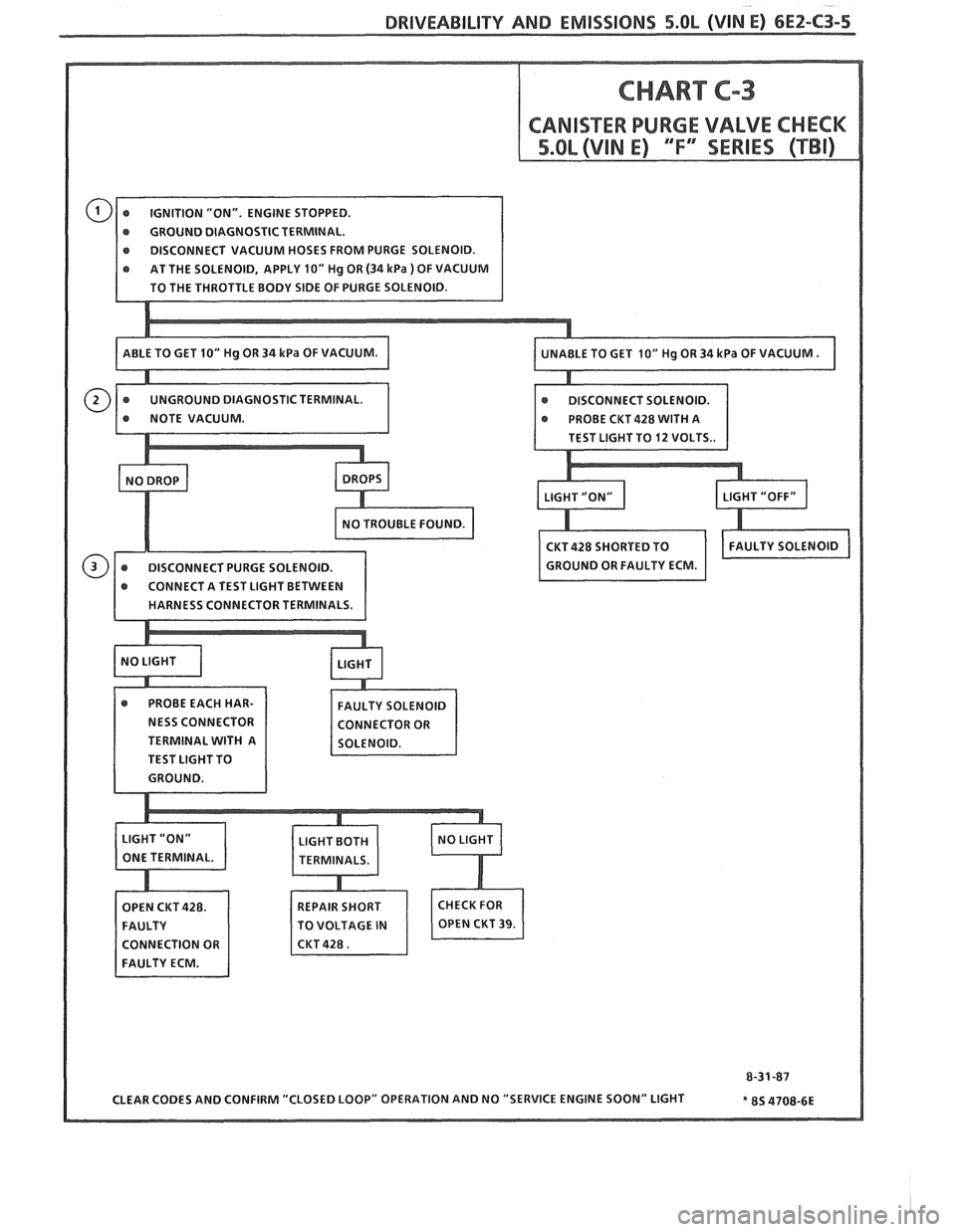
Test Description: Numbers below refer to circled
numbers on the diagnostic chart.
I. Checks to see if the solenoid is opened or closed.
The solenoid is energized in this step so it should
be open.
2. Completes functional check,
by grounding test
terminal. This should, normally, de-energize the
solenoid and allow the vacuum to drop (purge
"ON").
3. Checks for
a complete circuit. Normally, there is
battery voltage on CKT 39, and the ECM provides
a ground on CKT 428.
A shorted sole~oid could
cause an open circuit in the ECM.
Diagnostic Aids:
Normal operation of the canister purge solenoid is
described as follows:
With ignition "ON", engine stopped, diagnostic
terminal ungrounded, the purge solenoid will be
energized. With ignition "ON", engine "OFF", diagnostic
terminal grounded, the purge solenoid will be
de-energized.
Page 598 of 1825
DRIVEABILITY AND EMISSIBNO 5.OL (VIN E) 6E2-C3-5
r GROUND DIAGNOSTIC TERMINAL.
e DISCONNECT VACUUM HOSES FROM PURGE SOLENOID.
NESS CONNECTOR
TERMINAL WITH A
TEST LIGHT TO
REPAIR SHORT
TO VOLTAGE
IN
Page 599 of 1825

6EZ-C3-6 5.OL (VIN E) DRIVEABILITY AND EMISSIONS
BLANK
Page 600 of 1825
DRIVEABILITY AND EMISSIONS 5.QL (VIN E) 6Ef-C4-1
SECTION C4
IGNITION SYSTEM 1 (EST)
CQN"FEB\BTO
GENERAL DESCRIPTION ............... C4-1
PURPOSE ........................ C4-1
OPERATION
............*......... C4-1
DIAGNOSIS
........................ C4-1
..... RESULTS OF INCORRECT EST OPER. C4-1
HOW CODE 42 IS DETERMINED ....... C4-2
GENERAL DESCRIPTION
PURPOSE
The High Energy Ignition (HE11 system controls
fuel combustion by providing a spark to ignite the
compressed
aidfuel mixture at the correct time. To
provide improved engine performance, fuel economy,
and control of exhaust emissions, the ECM controls
distributor spark advance (timing) with the Electronic
Spark Timing (EST) system.
Only the Electronic Spark 'Timing (EST) system
will be described here. Additional information on the
HE1 system is found in Section 6D.
OPERATION
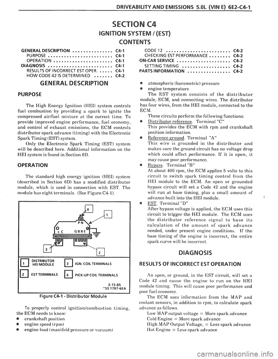
The standard high energy ignition (HEI) system
(described in Section 6D) has a modified distributor
module, which is used in connection with EST.
The
module has eight terminals. (See Figure C4-1).
IGN. COIL TERMINALS
EST TERMINALS PICK-UP
COIL TERMINALS
Figure C4-1 - Distributor Module
To properly control ignition/combustion timing,
the ECM needs to know:
@ crankshaft position
@ engine speed (rpm)
@ engine load (manifold pressure or vacuum)
CODE12 ........................ C4-2
CHECKING EST PERFORMANCE ........ C4-2
ON-CAR SERVICE ...a.e.............. C4-2
SETTING TIMING
.................. C4-2
PARTSINFORMATION ................ C4-2
@ atmospheric (barometric) pressure
@ engine temperature
The EST system consists of the distributor
module, ECM, and connecting wires. The distributor
has four wires, from the
HE1 module, connected to the
ECM.
These circuits perform the following functions:
@ Distributor reference. Terminal "C"
This provides the ECM with rpm and crankshaft
position information.
@ Reference ground. Terminal "A"
'I'his wire is grounded in the distributor and
makes sure the ground circuit has no voltage drop
which could affect performance. If it is open, it
may cause poor performance.
@ Bypass. Terminal "BJ'
At about 400 rpm, the ECM applies 5 volts to this
circuit to switch spark timing control
from the
HE1 module to the ECM. An open or grounded
bypass circuit will set a Code 42 and the engine
will run at base timing, plus a small
amount of
advance built into the
HE1 module.
@ EST. 'Terminal "D"
After bypass voltage is applied, the ECM uses this
circuit to trigger the
HE1 module. The ECM uses
the distributor reference signal to base its
calculation of the amount of spark advance
needed, under present engine conditions.
Lf the
base timing of the engine is incorrect, the entire
spark curve will be incorrect.
RESULTS OF INCORRECT EST OPERATION
An open, or ground, in the EST circuit, will set a
Code 42 and cause the engine to run on the HE1
module timing. 'I'his will cause poor performance and
poor fuel economy.
'I'he ECM uses information from the MAP and
coolant sensors, in addition to rpm, to calculate spark
advance as follows.
I,ow MAP output voltage = More spark advance
Cold Engine
= More spark advance
High
MAP Output Voltage, = Less spark advance
IIot 12ngine = 1,ess spark advance