PONTIAC FIERO 1988 Service Repair Manual
Manufacturer: PONTIAC, Model Year: 1988, Model line: FIERO, Model: PONTIAC FIERO 1988Pages: 1825, PDF Size: 99.44 MB
Page 661 of 1825
DIAGNOSTIC CIRCUIT CHECK
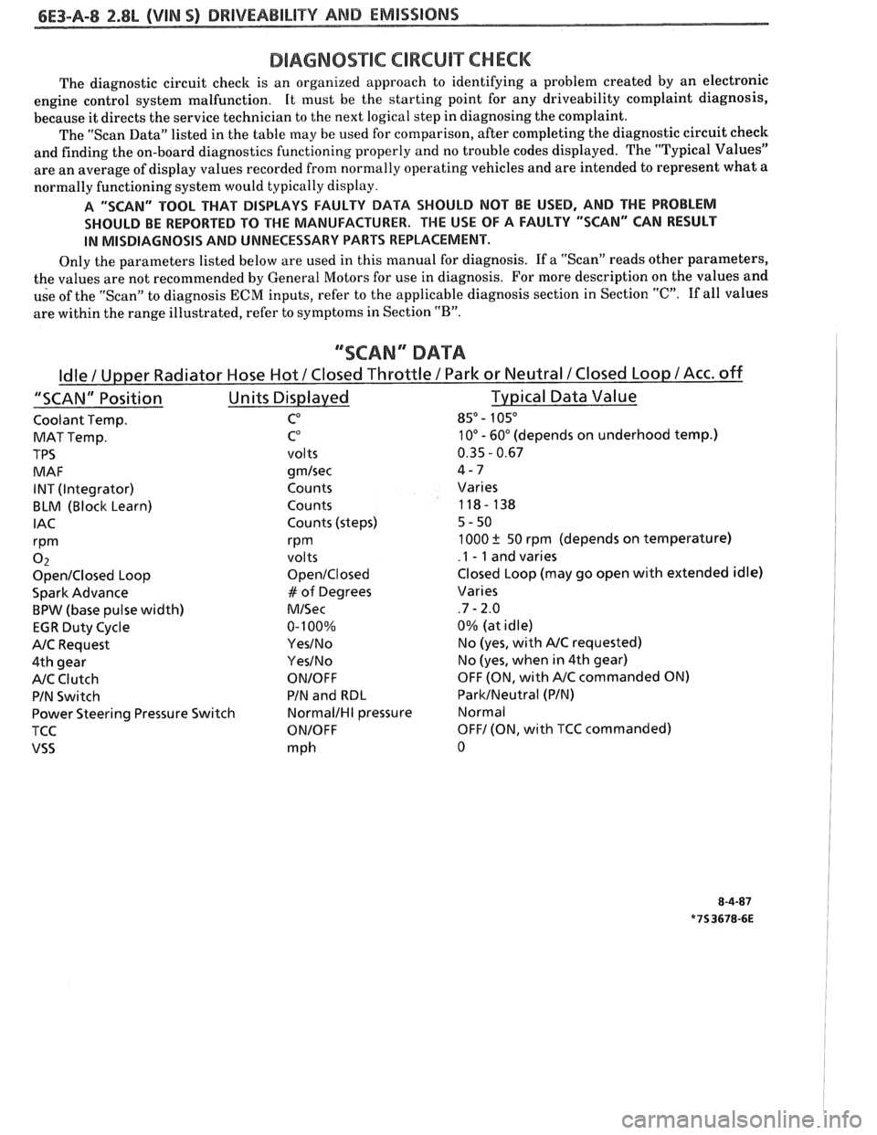
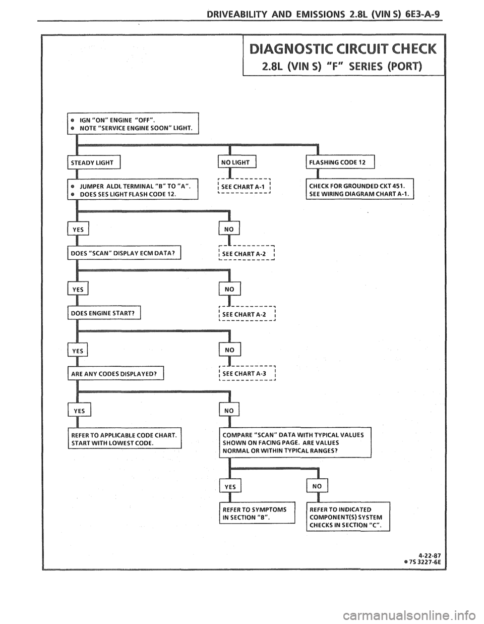
The diagnostic circuit check is an organized approach to identifying a problem created by an electronic
engine control system malfunction. It
must be the starting point for any driveability complaint diagnosis,
because it directs the service technician to the next logical step in diagnosing the complaint.
The "Scan Data" listed in the table may be used for comparison, after completing the diagnostic circuit check
and finding the on-board diagnostics functioning properly and no trouble codes displayed. The "Typical Values"
are an average of display values recorded from normally operating vehicles and are intended to represent what a
normally functioning system would typically display.
A "SCAN" TOOL THAT BiSPLAYS FAULTY DATA SHOULD NOT BE USED, AND THE PROBLEM
SHOULD BE REPORTED
TO THE MANUFACTURER. THE USE OF A FAULTY "SCAN" CAN RESULT
IN MISDIAGNOSIS AND UNNECESSARY PARTS REPLACEMENT.
Only the parameters listed below are used in this manual for diagnosis. If a "Scan" reads other parameters,
the values are not recommended by General Motors for use in diagnosis. For more description on the values and
use of the "Scan" to diagnosis
ECM inputs, refer to the applicable diagnosis section in Section "C". If all values
are within the range illustrated, refer to symptoms in Section
"B".
""SCAN" DATA
Coolant Temp. CO 85" - 105"
MAT Temp. C0 10" - 60" (depends on underhood temp.)
TPS
volts 0.35 - 0.67
MAF
gmlsec 4-7
INT (Integrator) Counts Varies
BLM (Block Learn) Counts 118- 138
IAC Counts (steps) 5-50
rPm rPm 1000 ? 50 rpm (depends on temperature)
0 2 volts .I - 1 and varies
OpenIClosed Loop OpenIClosed Closed Loop (may go open with extended idle)
Spark Advance
# of Degrees Varies
BPW (base pulse width) MISec .7 - 2.0
EGR Duty Cycle 0-
100% 0%
(at idle)
NC Request YesINo No (yes, with NC requested)
4th gear
YesINo No (yes, when in 4th gear)
NC Clutch ONIOFF OFF (ON, with NC commanded ON)
PIN Switch PIN
and
RBL ParkINeutral (PIN)
Power Steering Pressure Switch
NormalIHI pressure Normal
TCC
ONIOFF OFF1 (ON, with TCC commanded)
VSS mph 0
Page 662 of 1825
DRIVEABILITY AND EMISSIONS 2.8L (VlN S) 6E3-A-9
Page 663 of 1825
6E3-A-"I 2.8L (VlN S) DRIVEABILITY AND EMlSSlONS
TO OIL PRESS. SW.
&FUEL PUMP RELAY
FUSE
81 HOLDER BATTERY 12 V .. m.. . n.
. . . . . . . . FUSIBLE LINK
439 PNWBLK
419 BRNNVHT
SERIAL
DATA
451
WHTJBLK
450 BLKNVHT
ALDL CONNECTOR
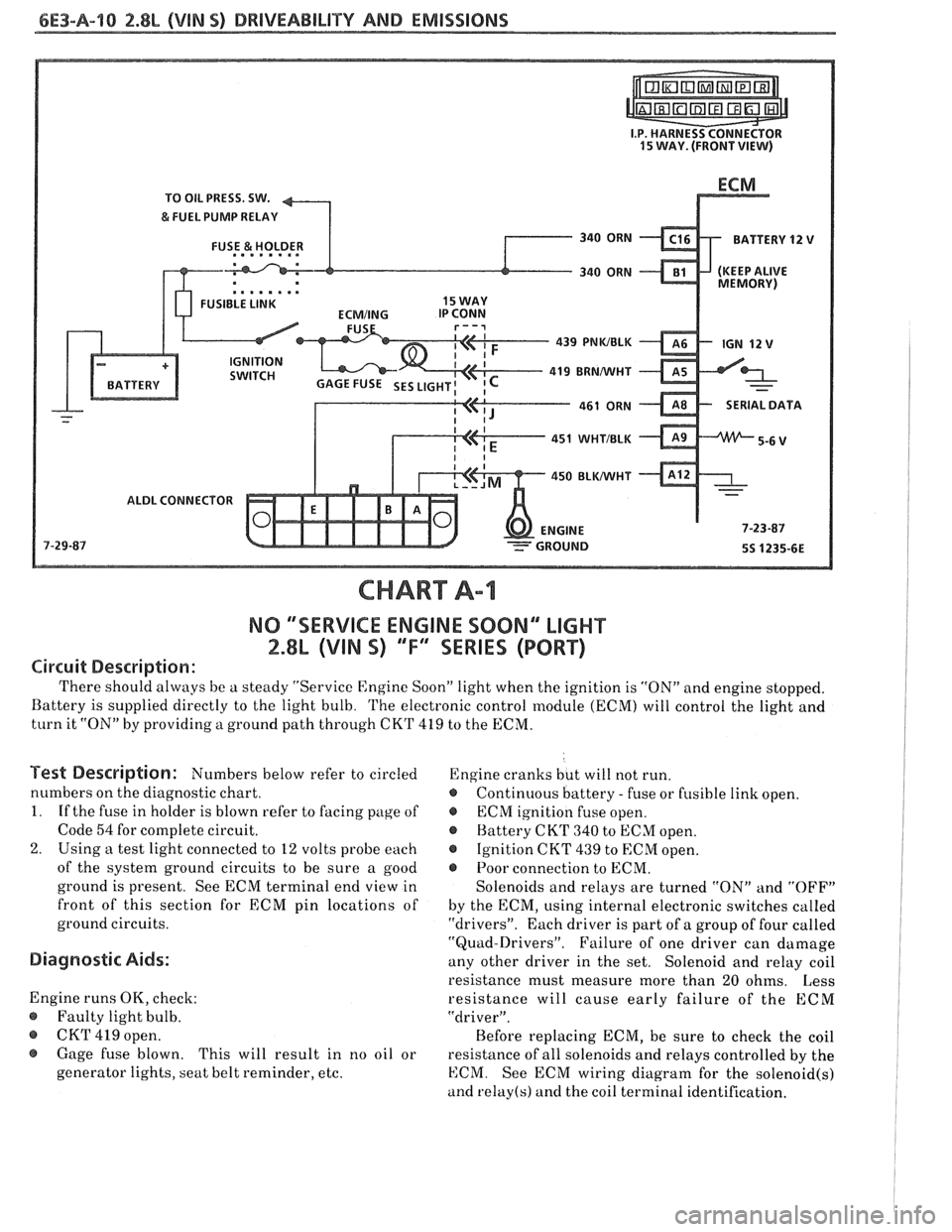
NO "SERVICE ENGlNE SOON" "LIGHT
2.8b (VIM 5) 'T" "SERIES (PORT)
Circuit Description:
There should always be a steady "Service Engine Soon" light when the ignition is "ON" and engine stopped.
Battery is supplied directly to the light bulb. The electronic control module
(ECNI) will control the light and
turn it "ON" by providing a ground path through CKT 419 to the ECM.
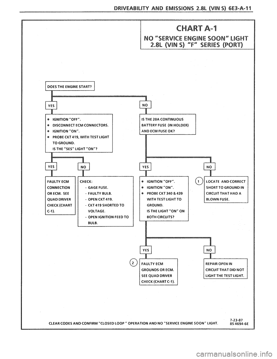
Test Description: Numbers below refer to circled
numbers on the diagnostic chart.
1. If the fuse in holder is blown refer to facing page of
Code
54 for complete circuit.
2. Using a test light connected to 12 volts probe each
of the system ground circuits to be sure a good
ground is present. See ECM terminal end view in
front of this section for
ECM pin locations of
ground circuits.
Diagnostic Aids:
Engine runs OK, check:
@ Faulty light bulb.
@ CKT 419 open.
@ Gage fuse blown.
This will result in no oil or
generator lights, seat belt reminder, etc. Engine
cranks but will not run.
@ Continuous battery - fuse or fusible link open.
@ ECM ignition fuse open.
@ Battery CKT 340 to ECM open.
@ Ignition CKT 439 to ECM open.
e Poor connection to ECM.
Solenoids and relays are turned "ON"
and "OFF"
by the ECM, using internal electronic switches called
"drivers". Each driver is part of a group of four called
"Quad-Drivers". Failure of one driver can damage
any other driver in the set. Solenoid and relay coil
resistance must measure more than 20 ohms. Less
resistance will cause early failure of the ECM
"driver".
Before replacing ECM, be sure to check the coil
resistance of all solenoids and relays controlled by the
ECM. See ECM wiring diagram for the
solenoid(s)
and relay(s) and the coil terminal identification.
Page 664 of 1825
DRIVEABILITY AND EMISSIONS 2.8L (VIN 5) 6E3-A-l l
CHART A-1
CLEAR CODES AND CONFIRM "CLOSED LOOP " OPERATION AND NO "SERVICE ENGINE SOON" LIGHT.
DISCONNECT
ECM CONNECTORS. BATTERY
FUSE (IN HOLDER)
IGNITION "ON".
PROBE
CUT 419, WITH TEST LIGHT
TO GROUND.
- GAGE FUSE. SHORT TO GROUND IN
- FAULTY BULB. @ PROBE CKT 340 & 439 CIRCUIT THAT HAD A
- OPEN CUT 419. WITH TEST LIGHT TO
- CKT 419 SHORTED TO
REPAIR OPEN IN
GROUNDS OR ECM. CIRCUIT THAT DID NOT
SEE QUAD DRIVER
CHECK (CHART
C-1).
Page 665 of 1825
6E3-A-92 2.8b (VIN SI DRIVEABILITY AND EMISSIONS
TO OIL PRESS. SW.
&FUEL PUMP RELAY
FUSE
& HOLDER BATTERY 12
V
.. am.. . FUSIBLE LINK 15 WAY
439
PNWBLK
- 419 BUNNVHT
SERIAL DATA
451
WHTIBLK
450 BLWHT
ALDL CONNECTOR
CHART A-2
NO ALDL OR WONT FLASH CODE 12
""SERVICE ENGlNE SOON" MGHT ""8N13SPEADY
2.8L (VIN S) ""FYSERlES (PORT)
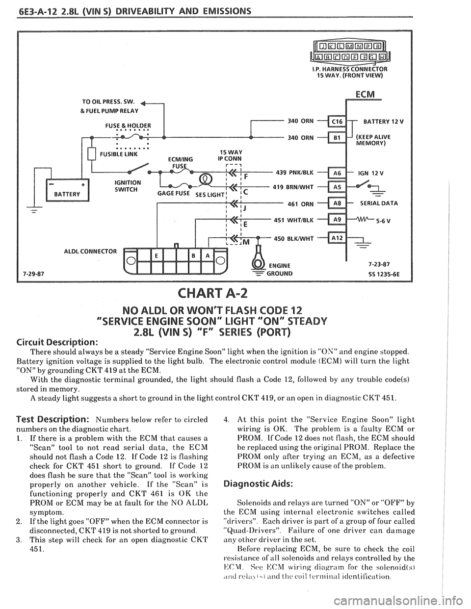
Circuit Description:
There should always be a steady "Service Engine Soon" light when the ignition is "ON" and engine stopped.
Battery ignition voltage is supplied to the light bulb. The electronic control module
(ECM) will turn the light
"ON" by grounding CKT
419 at the ECM.
With the diagnostic terminal grounded, the light should flash
a Code 12, followed by any trouble code(s)
stored in memory.
A steady light suggests a short to ground in the light control CKT 419, or an open in diagnostic CKT 451.
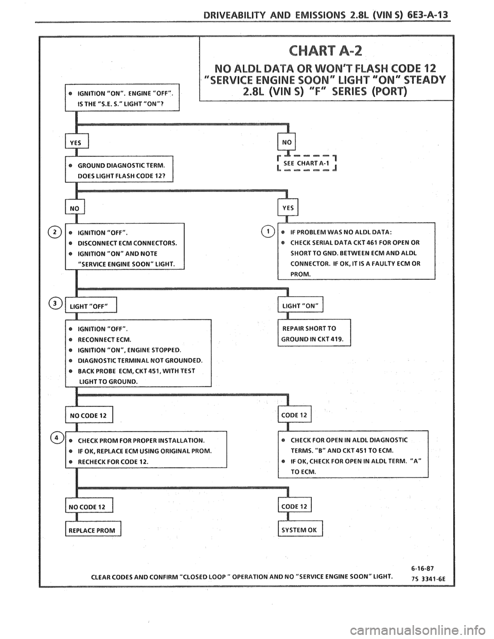
Test Description: Numbers below refer to circled
numbers on the diagnostic chart.
1. If there is a problem with the ECM that causes a
"Scan" tool to not read serial data, the ECM
should not flash a Code 12. If Code 12 is flashing
check for CKT
451 short to ground. If Code 12
does flash be sure that the "Scan" tool is working
properly on another vehicle. If the "Scan" is
functioning properly and CKT 461 is OK the
PROM or ECM may be at fault for the NO
AL,DI,
symptom.
2. If
the light goes "OFF" when the ECM connector is
disconnected, CKT 419 is not shorted to ground.
3. This step will check for an open diagnostic CKrl'
451.
4. At this point the "Service Engine Soon" light
wiring is OK. The problem is a faulty ECM or
PROM. If Code 12 does not flash, the ECM should
he replaced using the original PROM. Replace the
PROM only after trying an ECM, as a defective
PROM is an unlikely cause of the problem.
Diagnostic Aids:
Solenoids and relays are turned "ON" or "OFF" by
the ECM using internal electronic switches called
"drivers". Each driver is part of a group of four called
"Quad-l)rivers". Failure of one driver can damage
any other driver in the set.
Hefore replacing ECM, be sure to check the coil
resistance of
all solenoids and relays controlled by the
14:CM. Set: I':C%f wiring cliugrntn for the solcnoid(s)
.c~~cl rel;~ (-1 ~ititl lllc coil tcrtriitlul itlentilication.
Page 666 of 1825
DRIVEABILITY AND EMISSIONS 2.8b (VIN 5) 6E3-A-13
CHART A-2
NO ALDL DATA OR WONRT FLASH CODE 12
DISCONNECT ECM CONNECTORS.
IGNITION "ON" AND NOTE SHORT TO
GND. BETWEEN ECM AND ALDL
IGNITION "ON", ENGINE STOPPED.
KT
451, WITH TEST
IF OK, REPLACE ECM USING ORIGINAL PROM. TERMS.
"B" AND CKT 451 TO ECM.
Page 667 of 1825
6E3-A-14 2.8L (VIN S) DRIVEABILITY AND EMISSIONS
PICK-UP COIL
CHART A-3
(Page 1 of 2)
ENGINE CRANKS BUT WON'T RUN
2.8L (VIN S) ""F'" SERIES (PORT)
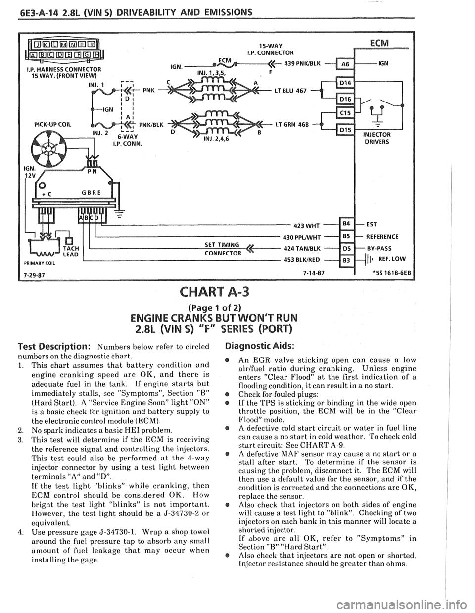
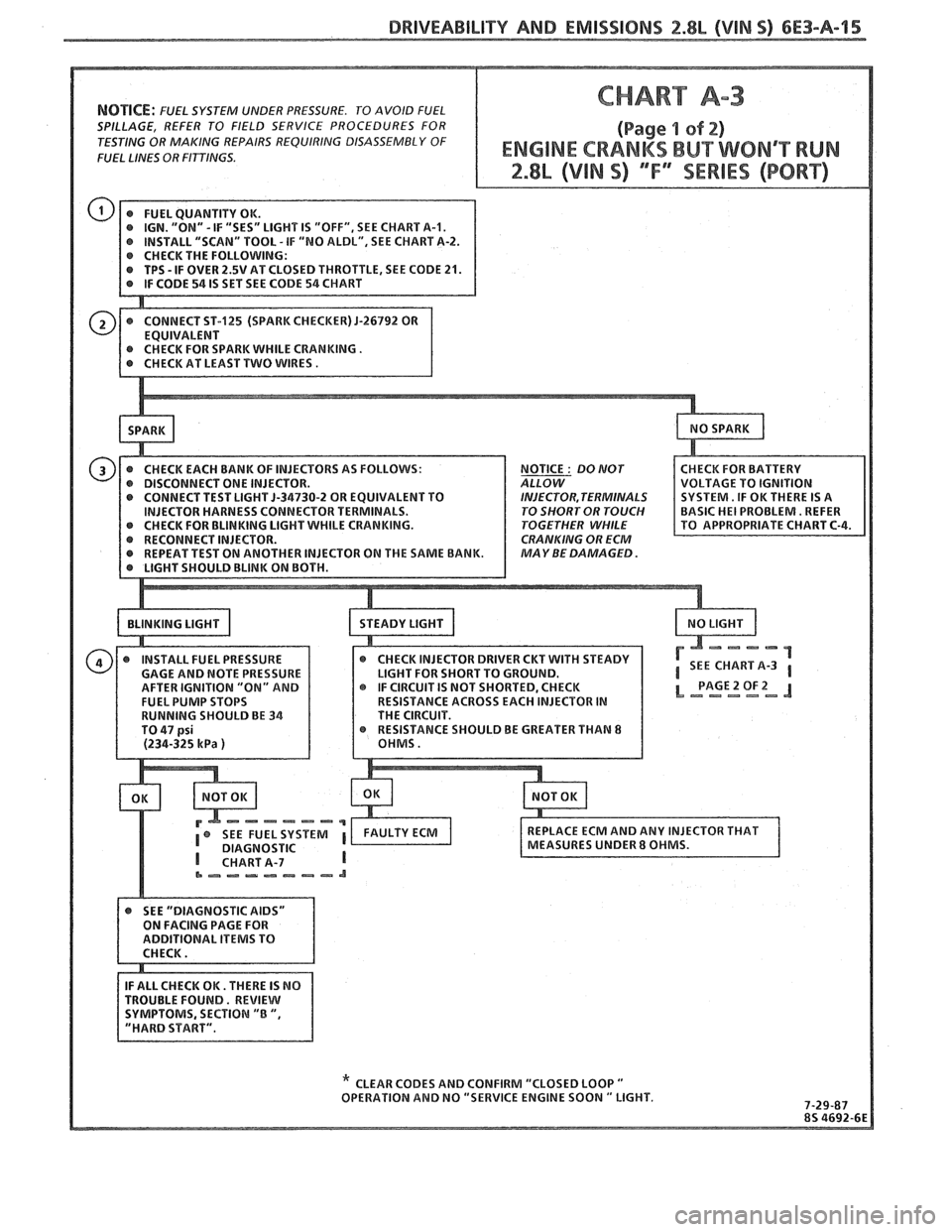
Test Description: Numbers below refer to circled
numbers on the diagnostic chart.
1. This chart
assunles that battery condition and
engine cranking speed are OK, and there is
adequate fuel in the tank. If engine starts but
immediately stalls, see "Symptoms", Section
"B"
(Hard Start). A "Service Engine Soon" light "ON"
is a basic check for ignition and battery supply to
the electronic control module
(ECM).
2. No sparlc indicates a basic HE1 problem.
3. This test will determine if the ECM is receiving
the reference signal and controlling the injectors.
This test could also be performed at the 4-way
injector connector by using a test light between
terminals
"A" and "D".
If the test light "blinks" while cranking, then
ECM control should be considered OK.
How
bright the test light "blinks" is not important.
However, the test light should be a
5-34730-2 or
equivalent.
4. Use pressure gage 5-34730-1. Wrap a shop towel
around the fuel pressure tap to absorb any small
amount of fuel leakage that may occur when
installing the gage.
Diagnostic Aids:
@ An EGR valve sticking open can cause a low
airlfuel ratio during cranking. Unless engine
enters "Clear Flood" at the first indication of a
flooding condition, it can result in a no start.
@ Check for fouled plugs:
@ If the TPS is sticking or binding in the wide open
throttle position, the ECM will be in the "Clear
Flood" mode.
@ A defective cold start circuit or water in fuel line
can cause a no start in cold weather.
To check cold
start circuit: See CHART
A-9.
e A defective MAF sensor may cause a no start or a
stall after start. 'I'o determine if the sensor is
causing the problem, disconnect it. The ECM will
then use a default value for the sensor, and if the
condition is corrected and the connections are OK,
replace the sensor.
@ Also check that injectors on both sides of engine
will cause a test light to "blink". Checking of two
injectors on each bank in this manner will locate a
shorted injector.
If
above are all OK, refer to "Symptoms" in
Section
"R" "Hard Start".
@ Also checlc that injectors are not open or shorted.
Injector resistance should be greater than ohms.
Page 668 of 1825
NOTICE: FUEL SYSTEM UNDER PRESSURE. TO AVOID FUEL
SPILLAGE, REFER TO FIELD SERVICE PROCEDURES FOR
TESTING OR MAKING REPAIRS
REQUlRlNG DISASSEMBLY OF
FUEL
LINES OR FITTINGS.
IGN. "ON" -IF "SES" LIGHT IS "OFF", SEE CHART A-I. r INSTALL "SCAN" TOOL - IF "NO ALDL", SEE CHART A-2. r CHECK THE FOLLOWING: r TPS - IF OVER 2.5V AT CLOSED THROTTLE, SEE CODE 21.
NOTICE
: 80 MOT
OR EQUIVALENT TO INJECTOR, TERMINALS R TERMINALS. TO SHORT OR TOUCH ILE CRANKING. TOGETHER WHILE
CRANKING OR ECM
MAY BE
DAMAGED.
SHOULD BE GREATER THAN 8
DIAGNOSTIC
&-,-m.---&?-a
TROUBLE FOUND. REVIEW
" CLEAR CODES AND CONFIRM "CLOSED LOOP " OPERATION AND NO "SERVICE ENGINE SOON " LIGHT.
Page 669 of 1825
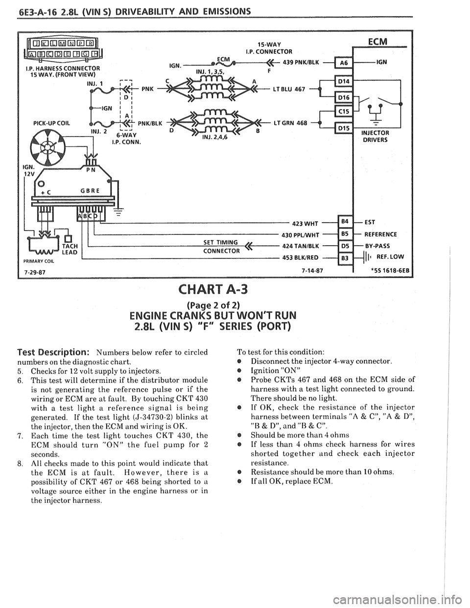
CHART A-3
(Page 2 of 2)
ENGINE CRANKS BUT WONT WN
2.8L (VIN S) ""FYSERIES (PORT)
Test Description: Numbers below refer to circled
numbers on the diagnostic chart.
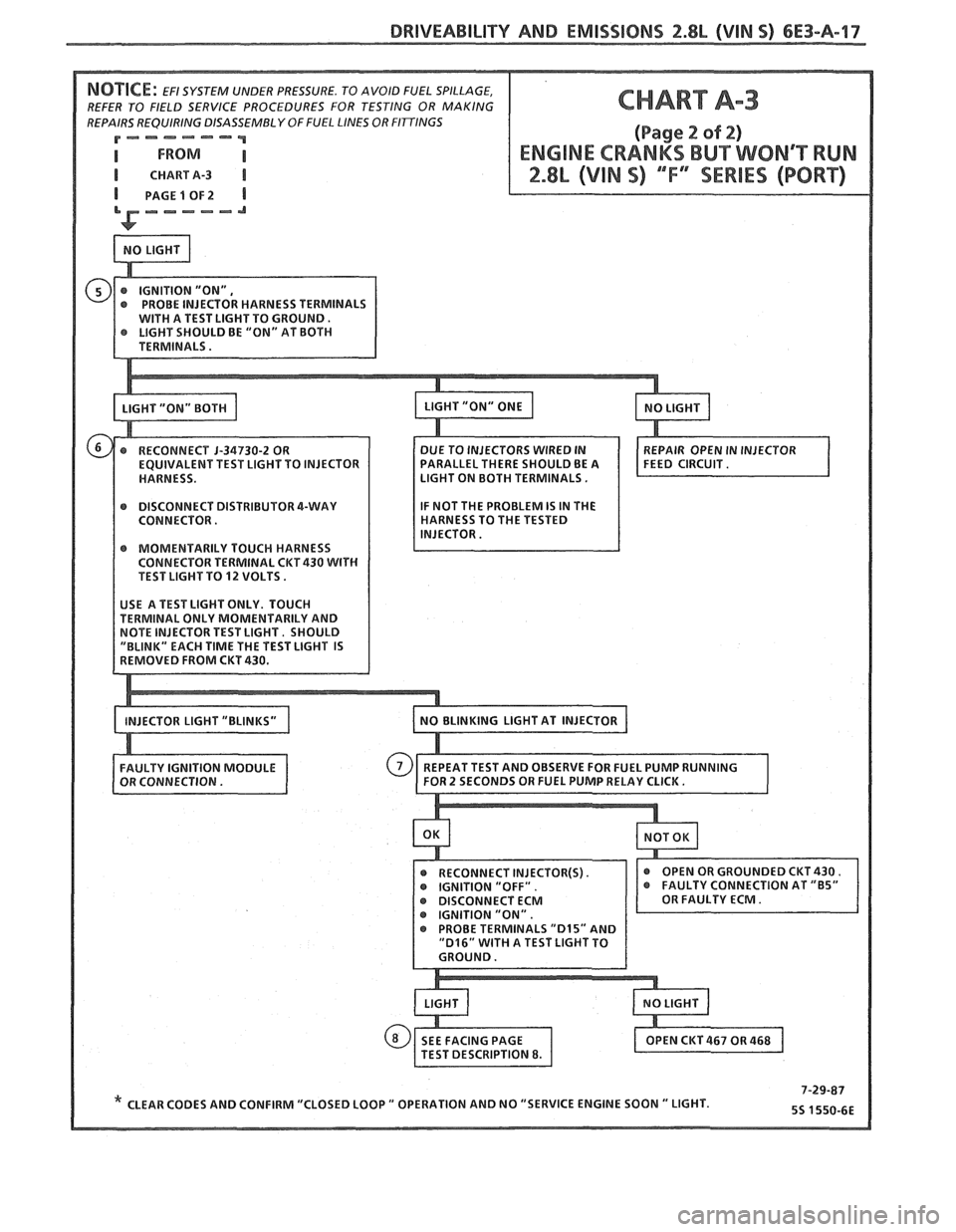
5. Checks for 12 volt supply to injectors.
6. This
test will determine if the distributor module
is not generating the reference pulse or if the
wiring or ECM are at fault. By touching CKT 430
with a test light a reference signal is being
generated. If the test light
(5-34730-2) blinks at
the injector, then the ECM and wiring is OK.
7. Each time
the test light touches CKT 430, the
ECM should turn "ON" the fuel
punlp for 2
seconds.
8. All
checks made to this point would indicate that
the ECM is at fault. However, there is
a
possibility of CKT 467 or 468 being shorted to a
voltage source either in the engine harness or in
the injector harness. To
test for this condition:
@ Disconnect the injector 4-way connector.
@ Ignition "ON"
Probe
CKTs 467 and 468 on the ECM side of
harness with a test light connected to ground.
There should be no light.
@ If OK, check the resistance of the injector
harness between terminals
"A & C", "A & D",
"B & D", and .'B & C".
@ Should be more than 4 ohms
@ If less than 4 ohms check harness for wires
shorted together and check each injector
resistance.
@ Resistance should be more than 10 ohms.
@ If all OK, replace ECM.
Page 670 of 1825
DRIVEABILITY AND EMISSIONS 2.8L (VIM 5) 6E3-A-17
REFER TO FIELD SERVICE PROCEDURES FOR TESTING OR MAKING
REPAIRS REQUIRING DISASSEMBLY
OFFUEL LINES OR FInlNGS
P=---=-'-"""
I CHARTA-3 I
PAGE 1 OF2
ARALLEL THERE SHOULD BE A IGHT ON BOTH TERMINALS.
r DISCONNECT DISTRIBUTOR 4-WAY
CONNECTOR.
r MOMENTARILY TOUCH HARNESS
CONNECTOR TERMINAL CKT 430 WITH TEST LIGHT TO 12 VOLTS.
* CLEAR CODES AND CONFIRM "CLOSED LOOP " OPERATION AND NO "SERVICE ENGINE SOON " LIGHT.