climate control Ram 2500 2020 User Guide
[x] Cancel search | Manufacturer: RAM, Model Year: 2020, Model line: 2500, Model: Ram 2500 2020Pages: 553, PDF Size: 21.99 MB
Page 66 of 553

64GETTING TO KNOW YOUR VEHICLE
Faceplate Auto Button
Touchscreen Auto Button AUTO
Press and release this button on the touchscreen, or push the button on the faceplate, to change the current setting. The
AUTO indicator illuminates when AUTO is on. This feature automatically controls the interior cabin temperature by adjusting
airflow distribution and amount. Toggling this function will cause the system to switch between manual mode and
automatic modes. Refer to “Automatic Operation” within this section for more information.
Front Defrost Button
Press and release the Front Defrost button on the touchscreen, or push and release the button on the faceplate, to change
the current airflow setting to Defrost mode. The Front Defrost indicator illuminates when Front Defrost is on. Air comes from
the windshield and side window demist outlets. When the defrost button is selected, the blower level may increase. Use
Defrost mode with maximum temperature settings for best windshield and side window defrosting and defogging. When
toggling the front defrost mode button, the climate system will return to previous setting.
Rear Defrost Button
Push and release the Rear Defrost button on the touchscreen, or push and release the button on the faceplate, to turn on
the rear window defroster and the heated outside mirrors (if equipped). The Rear Defrost indicator illuminates when the
rear window defroster is on. The rear window defroster automatically turns off after 15 minutes.
Icon
Description
20_DJD2_OM_EN_USC_t.book Page 64
Page 67 of 553
GETTING TO KNOW YOUR VEHICLE65
Faceplate Temperature
Knobs
Touchscreen
Temperature Buttons Driver and Passenger Temperature Up and Down Buttons
Provides the driver and passenger with independent temperature control. Push the red button (or rotate knob if equipped)
on the faceplate or touchscreen, or press and slide the temperature bar towards the red arrow button on the touchscreen
for warmer temperature settings. Push the blue button (or rotate knob if equipped) on the faceplate or touchscreen, or
press and slide the temperature bar towards the blue arrow button on the touchscreen for cooler temperature settings.
NOTE:
The numbers within the temperature display will only appear if the system is equipped with an automatic climate control
system.
Up and down buttons are only available on vehicles equipped with a 12-inch display.
SYNC
Press the SYNC button on the touchscreen to toggle the SYNC feature on/off. The SYNC indicator illuminates when SYNC is
on. SYNC synchronizes the passenger temperature setting with the driver temperature setting. Changing the passenger’s
temperature setting while in SYNC will automatically exit this feature.
NOTE:
The SYNC button is only available on the touchscreen.
Icon Description
2
20_DJD2_OM_EN_USC_t.book Page 65
Page 68 of 553
66GETTING TO KNOW YOUR VEHICLE
Faceplate Blower Knob
Touchscreen Blower Buttons Blower Control
Blower Control regulates the amount of air forced through the climate system. There are seven blower speeds available.
The speeds can be selected using either the blower control knob on the faceplate or the buttons on the touchscreen.
Faceplate: The blower speed increases as you turn the blower control knob clockwise from the lowest blower setting. The
blower speed decreases as you turn the blower control knob counterclockwise.
Touchscreen:
Use the small blower icon to reduce the blower setting and the large blower icon to increase the blower
setting. Blower can also be selected by pressing the blower bar area between the icons.
NOTE:
On Uconnect 4C NAV With 12–inch display radios, pressing the blower control button below one turns the Climate Control
system OFF.
Faceplate Mode Button
Touchscreen Mode Buttons Mode Control
Mode Control regulates the airflow distribution. The airflow distribution outlets are: instrument panel outlets, floor outlets,
defrost outlets, and demist outlets. Faceplate: Push the Mode Button to change the airflow distribution mode.
Touchscreen: Press one of the “MODE” buttons to change the airflow distribution mode.
The Mode settings are as follows:
Icon
Description
20_DJD2_OM_EN_USC_t.book Page 66
Page 69 of 553
GETTING TO KNOW YOUR VEHICLE67
Panel ModePanel Mode
Air comes from the outlets in the instrument panel. Each of these outlets can be individually adjusted to direct the flow of
air. The air vanes of the center outlets and outboard outlets can be moved up and down or side to side to regulate airflow
direction. There is a shut off wheel located below the air vanes to shut off or adjust the amount of airflow from these
outlets.
Bi-Level Mode Bi-Level Mode
Air comes from the instrument panel outlets and floor outlets. A slight amount of air is directed through the defrost and
side window demister outlets.
NOTE:
Bi-Level mode is designed under comfort conditions to provide cooler air out of the panel outlets and warmer air from the
floor outlets.
Floor Mode
Floor Mode
Air comes from the floor outlets. A slight amount of air is directed through the defrost and side window demister outlets.
Mix Mode Mix Mode
Air is directed through the floor, defrost, and side window demister outlets. This setting works best in cold or snowy
conditions that require extra heat to the windshield. This setting is good for maintaining comfort while reducing moisture on
the windshield.
Climate Control OFF Button
Press and release this button to turn the Climate Control ON/OFF.
Icon Description
2
20_DJD2_OM_EN_USC_t.book Page 67
Page 70 of 553

68GETTING TO KNOW YOUR VEHICLE
Climate Control Functions
A/C (Air Conditioning)
The Air Conditioning (A/C) button allows the
operator to manually activate or deactivate the
air conditioning system. When the air condi -
tioning system is turned on, cool dehumidified
air will flow through the outlets into the cabin.
For improved fuel economy, press the A/C
button to turn off the air conditioning and manu -
ally adjust the blower and airflow mode settings.
Also, make sure to select only Panel, Bi-Level, or
Floor modes.
NOTE:
For Manual Climate Controls, if the system is
in Mix, Floor or Defrost Mode, the A/C can be
turned off, but the A/C system shall remain
active to prevent fogging of the windows.
If fog or mist appears on the windshield or
side glass, select Defrost mode, and increase
blower speed if needed.
If your air conditioning performance seems
lower than expected, check the front of the
A/C condenser (located in front of the radi -
ator), for an accumulation of dirt or insects. Clean with a gentle water spray from the front
of the radiator and through the condenser.
MAX A/C
MAX A/C sets the control for maximum cooling
performance.
Press and release to toggle between MAX A/C
and the prior settings. The button illuminates
when MAX A/C is on.
In MAX A/C, the blower level and mode position
can be adjusted to desired user settings.
Pressing other settings will cause the MAX A/C
operation to switch to the selected setting and
MAX A/C to exit.
Recirculation
In cold weather, use of Recirculation mode may
lead to excessive window fogging. The Recircu -
lation feature may be unavailable (button on
the touchscreen greyed out) if conditions exist
that could create fogging on the inside of the
windshield.
On systems with Manual Climate Controls, if
equipped, the Recirculation mode is not
allowed in Defrost mode to improve window
clearing operation. Recirculation is disabled
automatically if this mode is selected. Attempting to use Recirculation while in this
mode causes the LED in the control button to
blink and then turns off.
Automatic Temperature Control (ATC)
Automatic Operation
1. Push the AUTO button on the faceplate, or the AUTO button on the touchscreen on the
Automatic Temperature Control (ATC)
Panel.
2. Next, adjust the temperature you would like the system to maintain by adjusting the
driver and passenger temperature control
buttons. Once the desired temperature is
displayed, the system will achieve and auto -
matically maintain that comfort level.
3. When the system is set up for your comfort level, it is not necessary to change the
settings. You will experience the greatest
efficiency by simply allowing the system to
function automatically.
20_DJD2_OM_EN_USC_t.book Page 68
Page 72 of 553

70GETTING TO KNOW YOUR VEHICLE
Outside Air Intake
Make sure the air intake, located directly in
front of the windshield, is free of obstructions,
such as leaves. Leaves collected in the air
intake may reduce airflow, and if they enter the
plenum, they could plug the water drains. In
Winter months, make sure the air intake is clear
of ice, slush, and snow.
Cabin Air Filter
The climate control system filters out dust and
pollen from the air. Contact an authorized
dealer to service your cabin air filter, and to
have it replaced when needed.
Operating Tips Chart
WINDOWS
Power Windows
Power Window Controls
Power Window Switches
The power window controls located on the
driver's door trim panel have up-down switches
that give you fingertip control of all power
windows. There is a single opening and closing
switch on the front passenger door for
passenger window control and on the rear
doors for rear window control. The windows will
operate when the ignition switch is placed in the
ON/RUN or ACC position, and for up to
10 minutes after the ignition is placed in the
OFF position or until a front door is opened.
WEATHER CONTROL
SETTINGS
Hot Weather And
Vehicle Interior Is Very Hot Set the mode control
to , on, and
blower on high. Roll
down the windows for a minute to flush out
the hot air. Adjust the
controls as needed to achieve comfort.
Warm Weather Turn on and set
the mode control to the position.
Cool Sunny Operate in
position.
Cool & Humid Conditions Set the mode control
to position and turn on to keep windows clear.
Cold Weather Set the mode control
to the position. If windshield fogging
starts to occur, move the control to the position.
WEATHER CONTROL
SETTINGS
20_DJD2_OM_EN_USC_t.book Page 70
Page 93 of 553
GETTING TO KNOW YOUR VEHICLE91
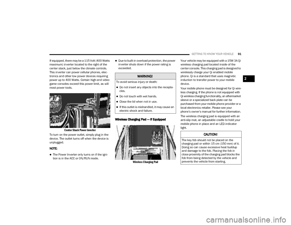
If equipped, there may be a 115 Volt (400 Watts
maximum) inverter located to the right of the
center stack, just below the climate controls.
This inverter can power cellular phones, elec -
tronics and other low power devices requiring
power up to 400 Watts. Certain high-end video
game consoles exceed this power limit, as will
most power tools.
Center Stack Power Inverter
To turn on the power outlet, simply plug in the
device. The outlet turns off when the device is
unplugged.
NOTE:
The Power Inverter only turns on if the igni -
tion is in the ACC or ON/RUN mode.
Due to built-in overload protection, the power
inverter shuts down if the power rating is
exceeded.
Wireless Charging Pad — If Equipped
Wireless Charging Pad
Your vehicle may be equipped with a 15W 3A Qi
wireless charging pad located inside of the
center console. This charging pad is designed to
wirelessly charge your Qi enabled mobile
phone. Qi is a standard that uses magnetic
induction to transfer power to your mobile
device.
Your mobile phone must be designed for Qi wire
-
less charging. If the phone is not equipped with
Qi wireless charging functionality, an aftermarket
sleeve or a specialized back plate can be
purchased from your mobile phone provider or a
local electronics retailer. Please see your
phone’s owner’s manual for further information.
The wireless charging pad is equipped with an
anti-slip mat, an adjustable cradle to hold your
mobile phone in place and an LED indicator
light.
WARNING!
To avoid serious injury or death:
Do not insert any objects into the recepta -
cles.
Do not touch with wet hands.
Close the lid when not in use.
If this outlet is mishandled, it may cause an
electric shock and failure.
CAUTION!
The key fob should not be placed on the
charging pad or within 15 cm (150 mm) of it.
Doing so can cause excessive heat buildup
and damage to the fob. Placing the fob in
close proximity of the charging pad blocks the
fob from being detected by the vehicle and
prevents the vehicle from starting.
2
20_DJD2_OM_EN_USC_t.book Page 91
Page 154 of 553
152SAFETY
Disabling And Enabling HSA
This feature can be turned on or turned off. To
change the current setting, proceed as follows:
If disabling HSA using your instrument cluster
display, refer to “Instrument Cluster Display”
in “Getting To Know Your Instrument Panel”
for further information.
If disabling HSA using Uconnect Settings,
refer to “Uconnect Settings” in “Multimedia”
for further information.
For vehicles not equipped with an instrument
cluster display, perform the following steps:
1. Center the steering wheel (front wheels pointing straight forward).
2. Shift the transmission into PARK.
3. Apply the parking brake.
4. Start the engine.
5. Rotate the steering wheel slightly more than one-half turn to the left. 6. Push the “ESC OFF” button located in the
lower switch bank below the climate control
four times within 20 seconds. The “ESC OFF
Indicator Light” should turn on and turn off
two times.
7. Rotate the steering wheel back to center and then an additional slightly more than
one-half turn to the right.
8. Place the ignition in the OFF mode and then back to ON. If the sequence was completed
properly, the “ESC OFF Indicator Light” will
blink several times to confirm HSA is
disabled.
9. Repeat these steps if you want to return this feature to its previous setting.
Towing With HSA
HSA will also provide assistance to mitigate roll
back while towing a trailer.
WARNING!
If you use a trailer brake controller with your
trailer, the trailer brakes may be activated
and deactivated with the brake switch. If
so, there may not be enough brake pres -
sure to hold both the vehicle and the trailer
on a hill when the brake pedal is released.
In order to avoid rolling down an incline
while resuming acceleration, manually acti -
vate the trailer brake or apply more vehicle
brake pressure prior to releasing the brake
pedal.
HSA is not a parking brake. Always apply
the parking brake fully when exiting your
vehicle. Also, be certain to place the trans -
mission in PARK.
Failure to follow these warnings can result
in a collision or serious personal injury.
20_DJD2_OM_EN_USC_t.book Page 152
Page 210 of 553

208SAFETY
(Continued)
(Continued)
Transporting Pets
Air Bags deploying in the front seat could harm
your pet. An unrestrained pet will be thrown
about and possibly injured, or injure a
passenger during panic braking or in a collision.
Pets should be restrained in the rear seat (if
equipped) in pet harnesses or pet carriers that
are secured by seat belts.
SAFETY TIPS
Transporting Passengers
NEVER TRANSPORT PASSENGERS IN THE
CARGO AREA.
Exhaust Gas The best protection against carbon monoxide
entry into the vehicle body is a properly main
-
tained engine exhaust system.
Whenever a change is noticed in the sound of
the exhaust system, when exhaust fumes can
be detected inside the vehicle, or when the
underside or rear of the vehicle is damaged,
have a competent mechanic inspect the
complete exhaust system and adjacent body
areas for broken, damaged, deteriorated, or
mispositioned parts. Open seams or loose
connections could permit exhaust fumes to
seep into the passenger compartment. In addi -
tion, inspect the exhaust system each time the
vehicle is raised for lubrication or oil change.
Replace as required.
WARNING!
Do not leave children or animals inside
parked vehicles in hot weather. Interior
heat build-up may cause serious injury or
death.
It is extremely dangerous to ride in a cargo
area, inside or outside of a vehicle. In a
collision, people riding in these areas are
more likely to be seriously injured or killed.
Do not allow people to ride in any area of
your vehicle that is not equipped with seats
and seat belts.
Be sure everyone in your vehicle is in a seat
and using a seat belt properly.
WARNING!
Exhaust gases can injure or kill. They contain
carbon monoxide (CO), which is colorless and
odorless. Breathing it can make you
unconscious and can eventually poison you.
To avoid breathing (CO), follow these safety
tips:
Do not run the engine in a closed garage or
in confined areas any longer than needed
to move your vehicle in or out of the area.
If you are required to drive with the trunk/
liftgate/rear doors open, make sure that all
windows are closed and the climate control
BLOWER switch is set at high speed. DO
NOT use the recirculation mode.
WARNING! (Continued)
If it is necessary to sit in a parked vehicle
with the engine running, adjust your
heating or cooling controls to force outside
air into the vehicle. Set the blower at high
speed.
WARNING! (Continued)
20_DJD2_OM_EN_USC_t.book Page 208
Page 440 of 553

438SERVICING AND MAINTENANCE
DEPARTMENT OF TRANSPORTATION
UNIFORM TIRE QUALITY GRADES
The following tire grading categories
were established by the National
Highway Traffic Safety Administration.
The specific grade rating assigned by the
tire's manufacturer in each category is
shown on the sidewall of the tires on
your vehicle.
All passenger vehicle tires must conform
to Federal safety requirements in addi -
tion to these grades.
Treadwear
The Treadwear grade is a comparative
rating, based on the wear rate of the tire
when tested under controlled conditions
on a specified government test course.
For example, a tire graded 150 would
wear one and one-half times as well on
the government course as a tire graded
100. The relative performance of tires
depends upon the actual conditions of
their use, however, and may depart
significantly from the norm due to varia -
tions in driving habits, service practices,
and differences in road characteristics
and climate.
Traction Grades
The Traction grades, from highest to
lowest, are AA, A, B, and C. These grades
represent the tire's ability to stop on wet
pavement, as measured under
controlled conditions on specified
government test surfaces of asphalt and
concrete. A tire marked C may have poor
traction performance.
Temperature Grades
The Temperature grades are A (the
highest), B, and C, representing the tire's
resistance to the generation of heat and
its ability to dissipate heat, when tested
under controlled conditions on a speci -
fied indoor laboratory test wheel.
Sustained high temperature can cause
the material of the tire to degenerate
and reduce tire life, and excessive
temperature can lead to sudden tire
failure. The grade C corresponds to a
level of performance, which all
passenger vehicle tires must meet
under the Federal Motor Vehicle Safety
When replacing a flat, the spare tire may
have to be remounted on the rim, or
installed at a different location, to maintain
the correct placement of the tire on the
wheel relative to the tire/wheel position on
the truck. For example, if the spare is used
to replace an outer rear tire it will have to be
remounted on the rim so that the wheel is
dished inward. That way the tread design of
asymmetrical tires and the white writing of
the OWL tires will maintain proper position.
CAUTION! (Continued)WARNING!
The traction grade assigned to this tire is
based on straight-ahead braking traction
tests, and does not include acceleration,
cornering, hydroplaning, or peak traction
characteristics.
20_DJD2_OM_EN_USC_t.book Page 438