reset Ram 2500 2020 User Guide
[x] Cancel search | Manufacturer: RAM, Model Year: 2020, Model line: 2500, Model: Ram 2500 2020Pages: 553, PDF Size: 21.99 MB
Page 127 of 553
GETTING TO KNOW YOUR INSTRUMENT PANEL125
Your vehicle has the ability to alert you to addi-
tional maintenance required on your vehicle or
engine. The following messages may display in
your instrument cluster display:
Perform Service — Your vehicle will require
emissions maintenance at a set interval. To
help remind you when this maintenance is
due, the instrument cluster display will
display “Perform Service”. When the
“Perform Service” message is displayed in
the instrument cluster display it is necessary
to have the emissions maintenance
performed. Emissions maintenance may
include replacing the Closed Crankcase
Ventilation (CCV) filter element. The proce -
dure for clearing and resetting the "Perform
Service" indicator message is located in the
appropriate Service Information.
Exhaust System — Regeneration Required
Now — "Exhaust Filter XX% Full Safely Drive at
Highway Speeds to Remedy" will be displayed
in the instrument cluster display if the
exhaust particulate filter reaches 80% of its
maximum storage capacity. Under conditions
of exclusive short duration and low speed
driving cycles, your Cummins diesel engine
and exhaust after-treatment system may
never reach the conditions required to
remove the trapped Particulate Matter (PM).
If this occurs, the “Exhaust Filter XX% Full
Safely Drive at Highway Speeds to Remedy”
message will be displayed in the instrument
cluster display. If this message is displayed,
you will hear one chime to assist in alerting
you of this condition
By simply driving your vehicle at highway
speeds for as little as 45 minutes, you can
remedy the condition in the particulate filter
system and allow your Cummins diesel
engine and exhaust after-treatment system
to remove the trapped Particulate Matter
(PM) and restore the system to normal oper -
ating condition.Exhaust System — Regeneration In Process
Exhaust Filter XX% Full — Indicates that the
Diesel Particulate Filter (DPF) is self-cleaning.
Maintain your current driving condition until
regeneration is completed.
Exhaust System — Regeneration Completed
— This message indicates that the Diesel
Particulate Filter (DPF) self-cleaning is
completed. If this message is displayed, you
will hear one chime to assist in alerting you of
this condition.
Exhaust Service Required — See Dealer Now
— This message indicates regeneration has
been disabled due to a system malfunction.
At this point the engine Powertrain Control
Module (PCM) will register a fault code, the
instrument panel will display a MIL light.
WARNING!
A hot exhaust system can start a fire if you
park over materials that can burn. Such
materials might be grass or leaves coming
into contact with your exhaust system. Do not
park or operate your vehicle in areas where
your exhaust system can contact anything
that can burn.
CAUTION!
See an authorized dealer, as damage to the
exhaust system could occur soon with
continued operation.
3
20_DJD2_OM_EN_USC_t.book Page 125
Page 128 of 553
126GETTING TO KNOW YOUR INSTRUMENT PANEL
Exhaust Filter Full — Power Reduced See
Dealer — This message indicates the PCM
has derated the engine to limit the likelihood
of permanent damage to the after-treatment
system. If this condition is not corrected and
a dealer service is not performed, extensive
exhaust after-treatment damage can occur.
To correct this condition it will be necessary
to have your vehicle serviced by your local
authorized dealer.
NOTE:
Failing to follow the oil change indicator,
changing your oil and resetting the oil change
indicator by 0 miles remaining will prevent the
diesel exhaust filter from performing it's
cleaning routine. This will shortly result in a
Malfunction Indicator Light (MIL) and reduced
engine power. Only an authorized dealer will be
able to correct this condition.Cold Ambient Derate Mode Messages
The vehicle will display messages when a
derate (engine power reduction) is activated to
protect the engine during start up in cold
ambient temperatures.
Engine Power Reduced During Warmup —
This message will display during start up
when the ambient temperature is between
10°F (-12°C) and -10°F (-23°C).
Engine Power Reduced Up To 30 Sec
(Seconds) During Warmup — This message
will display during start up when the ambient
temperature is between -10°F (-23°C) and
-25°F (-32°C).
Engine Power Reduced Up To 2 Min
(Minutes) During Warmup — This message
will display during start up when the ambient
temperature is -25°F (-32°C) and below.
Your vehicle is equipped with an engine
warm up protection feature that may limit
engine performance after cold starting at low
ambient temperatures. The length of time
engine speed is limited is dependent upon
engine coolant temperature. Engine speed
may be briefly limited to 1000 RPM after
starting with coolant temperature below freezing conditions, and may be limited to
1000 RPM for up to approximately 2 minutes
under more severe cold conditions.
Coolant Low
— This telltale will turn on to indi -
cate the vehicle coolant level is low. Refer to
“Dealer Service” in “Servicing And Mainte -
nance” for more information.
Diesel Exhaust Fluid (DEF) Warning
Messages
There are four different messages which are
displayed if the vehicle detects that the DEF
system has been filled with a fluid other than
DEF, has experienced component failures, or
when tampering has been detected. The vehicle
may be limited to a maximum speed of 5 MPH
(8 km/H) if the DEF system is not serviced
within less than 200 miles (322 km) of the fault
being detected.
When the DEF system needs to be serviced the
following warnings will display:
DEF Low Refill Soon — This message will
display when the low level is reached, during
vehicle start up, and with increased
frequency during vehicle operation. It will be
accompanied by a single chime. Approxi -
mately 5 gallons (19 Liters) of DEF is required
to refill the tank when this message is initially CAUTION!
See an authorized dealer, as damage to the
exhaust system could occur soon with
continued operation.
20_DJD2_OM_EN_USC_t.book Page 126
Page 156 of 553

154SAFETY
vehicle speed reaches approximately 6 mph
(10 km/h) or higher and will alert the driver of
vehicles in these areas.
NOTE:
The BSM system DOES NOT alert the driver
about rapidly approaching vehicles that are
outside the detection zones.
The Blind Spot Monitoring (BSM) system may
experience drop outs (blinking on and off) of
the side mirror Warning Indicator lamps
when a motorcycle or any small object
remains at the side of the vehicle for
extended periods of time (more than a couple
of seconds).
The vehicle’s taillights, where the radar sensors
are located, must remain free of snow, ice, and
dirt/road contamination so that the BSM
system can function properly. Do not block the
taillights with foreign objects (bumper stickers,
bicycle racks, etc.).
Radar Sensor Locations
If the system detects degraded performance
due to contamination or foreign objects, a
message will warn you of a blocked sensor and
the warning indicators in side view mirrors will
be on. The warning indicators will remain illumi -
nated until blockage clearing conditions are
met. First clear the taillights around the sensors
of the blockage. After removing the blockage,
the following procedure can be used to reset
the system, cycle the ignition from ON to OFF
and then back ON.
If the blockage message is still present after
cycling the ignition and driving in traffic, check
again for a blockage. The BSM system notifies the driver of objects in
the detection zones by illuminating the BSM
warning light located in the outside mirrors in
addition to sounding an audible (chime) alert
and reducing the radio volume. Refer to “Modes
Of Operation” in this section for further informa-
tion.
Warning Light Location
The BSM system monitors the detection zone
from three different entry points (side, rear,
front) while driving to see if an alert is neces -
sary. The BSM system will issue an alert during
these types of zone entries.
20_DJD2_OM_EN_USC_t.book Page 154
Page 159 of 553

SAFETY157
Modes Of Operation
Three selectable modes of operation are avail -
able in the Uconnect System.
Refer to “Uconnect Settings” in “Multimedia”
for further information.
Blind Spot Alert Lights Only
When operating in Blind Spot Alert mode, the
BSM system will provide a visual alert in the
appropriate side view mirror based on a
detected object. However, when the system is
operating in Rear Cross Path (RCP) mode, the
system will respond with both visual and
audible alerts when a detected object is
present. Whenever an audible alert is
requested, the radio is muted.
Blind Spot Alert Lights/Chime
When operating in Blind Spot Alert Lights/
Chime mode, the BSM system will provide a
visual alert in the appropriate side view mirror
based on a detected object. If the turn signal is
then activated, and it corresponds to an alert
present on that side of the vehicle, an audible
chime will also be sounded. Whenever a turn
signal and detected object are present on the
same side at the same time, both the visual and
audible alerts will be issued. In addition to the
audible alert the radio (if on) will also be muted. NOTE:
Whenever an audible alert is requested by the
BSM system, the radio is also muted.
When the system is in RCP, the system shall
respond with both visual and audible alerts
when a detected object is present. Whenever
an audible alert is requested, the radio is also
muted. Turn/hazard signal status is ignored;
the RCP state always requests the chime.
Blind Spot Alert Off
When the BSM system is turned off there will be
no visual or audible alerts from either the BSM
or RCP systems.
NOTE:
The BSM system will store the current operating
mode when the vehicle is shut off. Each time
the vehicle is started the previously stored
mode will be recalled and used.
Trailer Merge Assist
NOTE:
When Trailer Merge Assist is activated, Rear
Cross Path is disabled.
NOTE:
When a trailer with an electric brake is
connected to the vehicle, the instrument cluster
display will provide a menu to allow a selection
of the trailer type. There will be two options
provided: Conventional and Goose/Fifth Wheel.
Goose/Fifth Wheel Trailer is incompatible and
when selected, the BSM system will disable
until the trailer is disconnected. If the wrong
option is selected, the system can be reset by
either disconnecting and reconnecting the
trailer harness connector or disabling then
re-enabling the Blind Spot Monitoring System in
the customer settings in the Uconnect. This will
prompt the trailer selection menu again to allow
for the correct selection.
Trailer Merge Assist is a function of the Blind
Spot Monitoring (BSM) system that extends the
blind spot zone to work while pulling a trailer.
Trailer Merge Assist consists of three sub func
-
tions:Automatic Trailer Detection
Trailer Length Detection
Trailer Merge Warning
4
20_DJD2_OM_EN_USC_t.book Page 157
Page 163 of 553
SAFETY161
When the system determines a collision with
the vehicle in front of you is no longer probable,
the warning message will be deactivated.
NOTE:
The minimum speed for FCW activation is
3 mph (5 km/h).
The FCW alerts may be triggered on objects
other than vehicles such as guard rails or
sign posts based on the course prediction.
This is expected and is a part of normal FCW
activation and functionality.
It is unsafe to test the FCW system. To
prevent such misuse of the system, after four
Active Braking events within a key cycle, the
Active Braking portion of FCW will be deacti -
vated until the next key cycle.
The FCW system is intended for on-road use
only. If the vehicle is taken off-road, the FCW
system should be deactivated to prevent
unnecessary warnings to the surroundings.
FCW may not react to irrelevant objects such
as overhead objects, ground reflections,
objects not in the path of the vehicle,
stationary objects that are far away, oncoming traffic, or leading vehicles with the
same or higher rate of speed.
“FCW will be disabled like ACC, with the
unavailable screens.
During a FCW event when towing a trailer,
your Electronic Brake system will respond, to
activate the trailer brakes (if equipped).
Turning FCW On or Off
The FCW button is located in the Uconnect
display in the control settings. Refer to “Ucon
-
nect Settings” in “Multimedia” in the Owner's
Manual for further information.
To turn the FCW system on, press the forward
collision button once.
To turn the FCW system off, press the forward
collision button once.
NOTE:
When the FCW is “on”, this allows the system
to warn the driver of a possible collision with
the vehicle in front.
When the FCW is “off” prevents the system
from warning the driver of a possible collision
with the vehicle in front. If the FCW is set to
“off”, “FCW OFF" will be displayed in the
instrument cluster display.
When FCW status is set to “Only Warning”
prevents the system from providing limited
active braking, or additional brake support if
the driver is not braking adequately in the
event of a potential frontal collision.
When FCW status is set to “Warning and
Braking” this allows the system to warn the
driver of a possible collision with the vehicle
in front using audible/visual warnings and it
applies autonomous braking.
The FCW system state is defaulted to “Full
On” from one ignition cycle to the next. If the
system is turned off, it will reset to “Full On”
when the vehicle is restarted.
WARNING!
Forward Collision Warning (FCW) is not
intended to avoid a collision on its own, nor
can FCW detect every type of potential
collision. The driver has the responsibility to
avoid a collision by controlling the vehicle via
braking and steering. Failure to follow this
warning could lead to serious injury or death.
4
20_DJD2_OM_EN_USC_t.book Page 161
Page 172 of 553
170SAFETY
The customer may also store the pressure
values chosen for each axle in the radio as a
preset pressure. The customer will be allowed
to store up to two sets of preset values in the
radio for the front and rear axle pressure values.
Once the customer selects the tire pressures for
the front and rear axles that they want to inflate
or deflate to, they can begin inflating or
deflating one tire at a time.
NOTE:
The STFA system will only support inflating or
deflating one tire at a time.
The system will be activated when the TPM
receiver module detects a change in tire pres -
sure. The ignition must be in the RUN mode,
with the transmission in PARK (P).
The hazard lamps will come on to confirm the
vehicle is in Tire Fill Alert mode.
If the hazard lamps do not come on while
inflating or deflating the tire, the TPM sensor
may be in a inoperative position, preventing the
TPM sensor signal from being received. In this
case, the vehicle may need to be moved slightly
forward or backward. When Tire Fill Alert Mode is entered, the tire
pressure display screen will be displayed in the
instrument cluster.
Operation:
The horn will chirp once when the selected
pressure is reached to let the user know
when to stop inflating or deflating the tire.
The horn will chirp three times if the tire is
over inflated or over deflated and will
continue to chirp every five seconds if the
user continues to inflate or deflate the tire.
The horn will chirp once again when enough
air is added or removed to reach proper
selected pressure level.
Tire Pressure Information System (TPIS)
3500 Series Trucks
Your vehicle may be equipped with a Tire Pres
-
sure Information System (TPIS).
The Tire Pressure Information System (TPIS)
uses wireless technology with wheel rim
mounted electronic sensors to transmit tire
pressure levels. Sensors mounted to each
wheel as part of the valve stem transmit tire
pressure readings to the receiver module. NOTE:
It is particularly important for you to check the
tire pressure in all of the tires on your vehicle
monthly and to maintain the proper pressure.
The TPIS consists of the following components:
Receiver module
Four TPM sensors (Single Rear Wheel (SRW)
applications)
Six TPM sensors (Dual Rear Wheel (DRW)
applications)
Pressure display in the instrument cluster
The TPIS system will display all four (Single Rear
Wheel (SRW) applications) or six (Dual Rear
Wheel (DRW) applications) tire pressure values
in the instrument cluster display.
If a system fault is detected, the instrument
cluster will display a "SERVICE TPM SYSTEM"
message for a minimum of five seconds and
then display dashes (- -) in place of the pressure
value to indicate which sensor is not being
received.
If the ignition switch is cycled, this sequence will
repeat, providing the system fault still exists. If
the system fault no longer exists, the "SERVICE
TPM SYSTEM" message will no longer be
20_DJD2_OM_EN_USC_t.book Page 170
Page 191 of 553

SAFETY189
(Continued)
Enhanced Accident Response System
In the event of an impact, if the communication
network remains intact, and the power remains
intact, depending on the nature of the event,
the Occupant Restraint Controller (ORC) will
determine whether to have the Enhanced Acci -
dent Response System perform the following
functions:
Cut off fuel to the engine (if equipped)
Cut off battery power to the electric motor (if
equipped)
Flash hazard lights as long as the battery has
power
Turn on the interior lights, which remain on
as long as the battery has power or for
15 minutes from the intervention of the
Enhanced Accident Response System
Unlock the power door locks
Your vehicle may also be designed to perform
any of these other functions in response to the
Enhanced Accident Response System:
Turn off the Fuel Filter Heater, Turn off the
HVAC Blower Motor, Close the HVAC Circula -
tion Door
Cut off battery power to the:
Engine
Electric Motor (if equipped)
Electric power steering
Brake booster
Electric park brake
Automatic transmission gear selector
Horn
Front wiper
Headlamp washer pump
NOTE:
After an accident, remember to cycle the ignition
to the STOP (OFF/LOCK) position and remove the
key from the ignition switch to avoid draining the
battery. Carefully check the vehicle for fuel leaks
in the engine compartment and on the ground
near the engine compartment and fuel tank
before resetting the system and starting the
engine. If there are no fuel leaks or damage to the
vehicle electrical devices (e.g. headlights) after an
accident, reset the system by following the proce -
dure described below. If you have any doubt,
contact an authorized dealer.
Enhanced Accident Response System Reset
Procedure
In order to reset the Enhanced Accident
Response System functions after an event, the
ignition switch must be changed from ignition
START or ON/RUN to ignition OFF. Carefully
check the vehicle for fuel leaks in the engine
compartment and on the ground near the
engine compartment and fuel tank before reset -
ting the system and starting the engine.
Maintaining Your Air Bag System
WARNING!
Modifications to any part of the air bag
system could cause it to fail when you need
it. You could be injured if the air bag system
is not there to protect you. Do not modify
the components or wiring, including adding
any kind of badges or stickers to the
steering wheel hub trim cover or the upper
passenger side of the instrument panel. Do
not modify the front bumper, vehicle body
structure, or add aftermarket side steps or
running boards.
4
20_DJD2_OM_EN_USC_t.book Page 189
Page 220 of 553
218STARTING AND OPERATING
5. After engine start-up, check to see that
there is oil pressure.
6. Release the parking brake and drive.
NOTE:
Engine idle speed will automatically increase
to 1,000 RPM and engage the Variable
Geometry Turbocharger at low coolant
temperatures to improve engine warm-up.
The engine will not automatically crank after
the engine “Wait To Start” telltale goes off if
a door or the hood is ajar.
If the engine stalls, or if the ignition switch is
left ON for more than two minutes after the
“Wait To Start” telltale goes out, reset the
intake air heater by turning the ignition
switch to the OFF position for at least
5 seconds and then back ON. Repeat steps
1 through 7 of “Keyless Enter-N-Go Starting Procedure – Engine Manifold Air Tempera
-
ture Below 66° F (19° C).”
Extreme Cold Weather
The Cummins® Turbo Diesel engine is
equipped with several features designed to
assist cold weather starting and operation:
The engine block heater is a resistance
heater installed in the water jacket of the
engine just above and behind the oil filter. It
requires a 110–115 Volt AC electrical outlet
with a grounded, three-wire extension cord.
NOTE:
The engine block heater cord is a factory
installed option. If your vehicle is not equipped,
heater cords are available from an authorized
Mopar dealer.
A 12 Volt heater built into the fuel filter hous -
ings aid in preventing fuel gelling. It is
controlled by a built-in thermostat.
A intake air heater system both improves
engine starting and reduces the amount of
white smoke generated by a warming engine.
Normal Starting Procedure — Engine
Manifold Air Temperature Above 66° F
(19° C)
Observe the instrument panel cluster lights
when starting the engine.
1. Always apply the parking brake.
2. Shift into PARK for an automatic transmis -
sion.
3. Place the ignition switch in the ON position and watch the instrument panel cluster
lights.
4. Place the ignition switch in the START posi -
tion and crank the engine. Do not press the
accelerator during starting.
CAUTION!
Do not crank engine for more than 25 seconds
at a time or starter motor damage may result.
Turn the ignition switch to the OFF position and
wait at least two minutes for the starter to cool
before repeating start procedure.
CAUTION!
If the “Water in Fuel Indicator Light” remains
on, DO NOT START the engine before you
drain the water from the fuel filters to avoid
engine damage. Refer to “Draining Fuel/
Water Separator Filter” in “Servicing And
Maintenance” for further information.
20_DJD2_OM_EN_USC_t.book Page 218
Page 222 of 553

220STARTING AND OPERATING
completes, the driver’s foot should be fully
removed from the brake pedal prior to
pushing the start button again in order for the
ignition to move directly to off.
If the engine stalls, or if the ignition switch is
left ON for more than two minutes after the
“Wait To Start” telltale goes out, reset the
intake air heater by turning the ignition
switch to the OFF position for at least five
seconds and then back ON. Repeat steps
1 through 5 of “Starting Procedure – Engine
Manifold Air Temperature Below 66°F
(19°C).”
Starting Procedure — Engine Manifold Air
Temperature Below 0°F (-18°C)
In extremely cold weather below 0°F (-18°C) it
may be beneficial to cycle the intake air heater
twice before attempting to start the engine. This
can be accomplished by turning the ignition OFF
for at least 5 seconds and then back ON after
the “Wait To Start” telltale has turned off, but
before the engine is started. However, exces -
sive cycling of the intake air heater will result in
damage to the heater elements or reduced
battery voltage. NOTE:
If multiple pre-heat cycles are used before
starting, additional engine run time may be
required to maintain battery state of charge at a
satisfactory level.
1. If the engine stalls after the initial start, the
ignition must be turned to the OFF position
for at least five seconds and then to the ON
position to recycle the intake air heater.
NOTE:
Excessive white smoke and poor engine perfor -
mance will result if intake air heater are not
recycled.
2. Heat generated by the intake air heater dissipates rapidly in a cold engine. If more
than two minutes pass between the time
the “Wait To Start” telltale turns off and the
engine is started, recycle the intake air
heater by turning the ignition switch to the
OFF position for at least five seconds and
then back ON.
3. If the vehicle is driven and vehicle speed exceeds 19 mph (31 km/h) before the
intake air heater post-heat (after start) cycle
is complete, the intake air heater will shut
off. 4. If the engine is cranked for more than
10 seconds, the post-heat cycle will turn off.
NOTE:
Engine idle speed will automatically increase
to 1,000 RPM and engage the Variable
Geometry Turbocharger at low coolant
temperatures to improve engine warm-up.
When a diesel engine is allowed to run out of
fuel or the fuel gels at low temperatures, air
is pulled into the fuel system. If your engine
has run out of fuel, refer to “Dealer Service/
Priming If The Engine Has Run Out Of Fuel” in
“Servicing And Maintenance” for further
information.
If the engine stalls, or if the ignition switch is
left ON for more than two minutes after the
“Wait To Start” telltale goes out, reset the
intake air heater by turning the ignition
switch to the OFF position for at least 5
seconds and then back ON. Repeat steps
1 through 5 of “Starting Procedure – Engine
Manifold Air Temperature Below 66°F
(19°C).”
20_DJD2_OM_EN_USC_t.book Page 220
Page 238 of 553
236STARTING AND OPERATING
Transmission Limp Home Mode
Transmission function is monitored electroni -
cally for abnormal conditions. If a condition is
detected that could result in transmission
damage, Transmission Limp Home Mode is acti -
vated. In this mode, the transmission may
operate only in certain gears, or may not shift at
all. Vehicle performance may be severely
degraded and the engine may stall. In some
situations, the transmission may not re-engage
if the engine is turned off and restarted. The
Malfunction Indicator Light (MIL) may be illumi -
nated. A message in the instrument cluster will
inform the driver of the more serious conditions,
and indicate what actions may be necessary.
In the event of a momentary problem, the trans -
mission can be reset to regain all forward gears
by performing the following steps:
NOTE:
In cases where the instrument cluster message
indicates the transmission may not re-engage
after engine shutdown, perform this procedure
only in a desired location (preferably, at an
authorized dealer).
1. Stop the vehicle.
2. Shift the transmission into PARK, if
possible. If not, shift the transmission to
NEUTRAL.
3. Push and hold the ignition switch until the engine turns off.
4. Wait approximately 30 seconds.
5. Restart the engine.
6. Shift into the desired gear range. If the problem is no longer detected, the trans -
mission will return to normal operation.
NOTE:
Even if the transmission can be reset, we
recommend that you visit an authorized dealer
at your earliest possible convenience. An autho -
rized dealer has diagnostic equipment to
assess the condition of your transmission.
If the transmission cannot be reset, authorized
dealer service is required.
Electronic Range Select (ERS) Operation
The Electronic Range Select (ERS) shift control
allows the driver to limit the highest available
gear when the transmission is in DRIVE. For
example, if you set the transmission gear limit
to 4 (FOURTH gear), the transmission will not shift above FOURTH gear (except to prevent
engine overspeed), but will shift through the
lower gears normally.
You can switch between DRIVE and ERS mode
at any vehicle speed. When the transmission
gear selector is in DRIVE, the transmission will
operate automatically, shifting between all
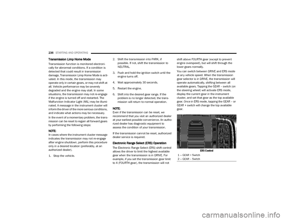
available gears. Tapping the GEAR – switch (on
the steering wheel) will activate ERS mode,
display the current gear in the instrument
cluster, and set that gear as the top available
gear. Once in ERS mode, tapping the GEAR – or
GEAR + switch will change the top available
gear.
ERS Control
1 — GEAR + Switch
2 — GEAR – Switch
20_DJD2_OM_EN_USC_t.book Page 236