lock Ram 2500 2020 Owner's Guide
[x] Cancel search | Manufacturer: RAM, Model Year: 2020, Model line: 2500, Model: Ram 2500 2020Pages: 553, PDF Size: 21.99 MB
Page 68 of 553
66GETTING TO KNOW YOUR VEHICLE
Faceplate Blower Knob
Touchscreen Blower Buttons Blower Control
Blower Control regulates the amount of air forced through the climate system. There are seven blower speeds available.
The speeds can be selected using either the blower control knob on the faceplate or the buttons on the touchscreen.
Faceplate: The blower speed increases as you turn the blower control knob clockwise from the lowest blower setting. The
blower speed decreases as you turn the blower control knob counterclockwise.
Touchscreen:
Use the small blower icon to reduce the blower setting and the large blower icon to increase the blower
setting. Blower can also be selected by pressing the blower bar area between the icons.
NOTE:
On Uconnect 4C NAV With 12–inch display radios, pressing the blower control button below one turns the Climate Control
system OFF.
Faceplate Mode Button
Touchscreen Mode Buttons Mode Control
Mode Control regulates the airflow distribution. The airflow distribution outlets are: instrument panel outlets, floor outlets,
defrost outlets, and demist outlets. Faceplate: Push the Mode Button to change the airflow distribution mode.
Touchscreen: Press one of the “MODE” buttons to change the airflow distribution mode.
The Mode settings are as follows:
Icon
Description
20_DJD2_OM_EN_USC_t.book Page 66
Page 74 of 553
72GETTING TO KNOW YOUR VEHICLE
Window Lockout Switch
The window lockout switch on the driver's door
allows you to disable the window control on the
rear passenger doors. To disable the window
controls on the rear passenger doors, push the
window lock switch into the latched or down
position. To enable the window controls, push
the window lock switch again and return the
switch to the released or up position.
Window Lockout Switch
Power Sliding Rear Window — If Equipped
The switch for the power sliding rear window is
located on the overhead console.
Power Sliding Rear Window Switch
Push the rearward portion of the switch to open
the window. Push the forward portion of the
switch to close the window.
Manual Sliding Rear Window — If Equipped
A locking device in the center of the window
helps to prevent entry from the rear of the
vehicle. Squeeze the lock to release the
window.
Wind Buffeting
Wind buffeting can be described as the percep -
tion of pressure on the ears or a helicopter-type
sound in the ears. Your vehicle may exhibit wind
buffeting with the windows down, or the sunroof
(if equipped) in certain open or partially open
positions. This is a normal occurrence and can
be minimized. If the buffeting occurs with the rear windows open, open the front and rear
windows together to minimize the buffeting. If
the buffeting occurs with the sunroof open,
adjust the sunroof opening to minimize the
buffeting or open any window.
POWER SUNROOF — IF EQUIPPED
Single Pane Power Sunroof — If Equipped
The power sunroof switches are located on the
overhead console between the courtesy/
reading lights.
Power Sunroof Switches
1 — Opening/Closing Sunroof
2 — Venting Sunroof
20_DJD2_OM_EN_USC_t.book Page 72
Page 75 of 553

GETTING TO KNOW YOUR VEHICLE73
Opening Sunroof
Express
Push the switch rearward and release it within
one-half second. The sunroof and sunshade will
open automatically and stop when the full open
position is reached. This is called “Express
Open.” During Express Open operation, any
other actuation of the sunroof switch will stop
the sunroof.
Manual Mode
To open the sunroof, push and hold the switch
rearward. The sunroof will move rearward and
automatically stop at full open position. Any
release of the switch will stop the movement.
The sunroof and sunshade will remain in a
partially opened condition until the sunroof
switch is pushed again.
Closing Sunroof
Express
Push the switch forward and release it within
one-half second and the sunroof will close auto -
matically from any position. The sunroof will
close fully and stop automatically. This is called
“Express Close.” During Express Close opera -
tion, any other actuation of the switch will stop
the sunroof. Manual Mode
To close the sunroof, push and hold the switch
forward. The sunroof will move forward and
automatically stop at full closed position. Any
release of the switch will stop the movement
and the sunroof will remain in a partially closed
condition until the sunroof switch is pushed
again.
Wind Buffeting
Wind buffeting can be described as the percep
-
tion of pressure on the ears or a helicopter-type
sound in the ears. Your vehicle may exhibit wind
buffeting with the windows down, or the sunroof
(if equipped) in certain open or partially open
positions. This is a normal occurrence and can
be minimized. If the buffeting occurs with the
rear windows open, then open the front and
rear windows together to minimize the
buffeting. If the buffeting occurs with the
sunroof open, adjust the sunroof opening to
minimize the buffeting or open any window.
WARNING!
Never leave children unattended in a
vehicle, or with access to an unlocked
vehicle. Never leave the key fob in or near
the vehicle, or in a location accessible to
children. Do not leave the ignition of a
vehicle equipped with Keyless Enter-N-Go
in the ACC or ON/RUN mode. Occupants,
particularly unattended children, can
become entrapped by the power sunroof
while operating the power sunroof switch.
Such entrapment may result in serious
injury or death.
In a collision, there is a greater risk of being
thrown from a vehicle with an open sunroof.
You could also be seriously injured or killed.
Always fasten your seat belt properly and
make sure all passengers are also properly
secured.
Do not allow small children to operate the
sunroof. Never allow your fingers, other
body parts, or any object, to project through
the sunroof opening. Injury may result.
2
20_DJD2_OM_EN_USC_t.book Page 73
Page 77 of 553
GETTING TO KNOW YOUR VEHICLE75
To Close The Hood
Lower the hood to approximately 12 inches
(30 cm) from the engine compartment and drop
it. Make sure that the hood is completely
closed.
TAILGATE
Opening
The power tailgate may be opened by pushing
the tailgate release pad located on the tailgate
door.
The tailgate damper strut will lower the tailgate
to the open position (if equipped).
Electronic Tailgate Release — If Equipped
The key fob may be equipped with an
electronic release feature for the tail-
gate, allowing hands-free tailgate
opening. To activate, push and
release the Tailgate Release button on the key
fob twice within five seconds. The tailgate door
will unlatch, and slowly lower into the open posi -
tion.
If equipped, a button on the center overhead
console inside the vehicle can be used to
release the tailgate.
NOTE:
The Tri-Fold Tonneau Cover (if equipped) may
prevent Electronic Tailgate Release if installed.
The Tonneau Cover must be removed or folded
up before releasing the tailgate. Refer to “Tri-Fold Tonneau Cover — If Equipped” in this
chapter for further information.
Closing
To close the tailgate, push it upward until both
sides are latched.
NOTE:
Pull back on the tailgate firmly after closing to
ensure it is securely latched.
Bed Step — If Equipped
Your vehicle may be equipped with an extend
-
able bed step on the driver’s side of the tailgate
to provide easier entry and exit into the truck
bed.
Bed Step Location
WARNING!
Be sure the hood is fully latched before
driving your vehicle. If the hood is not fully
latched, it could open when the vehicle is in
motion and block your vision. Failure to follow
this warning could result in serious injury or
death.
CAUTION!
To prevent possible damage, do not slam the
hood to close it. Use a firm downward push at
the front center of the hood to ensure that
both latches engage.
2
20_DJD2_OM_EN_USC_t.book Page 75
Page 82 of 553

80GETTING TO KNOW YOUR VEHICLE
(Continued)
4. Watch for the HomeLink® indicator to change flash rates. When it changes, it is
programmed. It may take up to 30 seconds
or longer in rare cases. The garage door
may open and close while you are program -
ming.
5. Press and hold the programmed Home -
Link® button and observe the indicator
light.
NOTE:
If the indicator light stays on constantly,
programming is complete and the garage
door/device should activate when the Home -
Link® button is pressed.
To program the two remaining HomeLink®
buttons, repeat each step for each remaining
button. DO NOT erase the channels.
If you unplugged the garage door opener/
device for programming, plug it back in at this
time.
Reprogramming A Single HomeLink® Button
(Canadian/Gate Operator)
To reprogram a channel that has been previ -
ously trained, follow these steps:
1. Place the ignition in the ON/RUN position.
2. Press and hold the desired HomeLink®
button until the indicator light begins to
flash after 20 seconds. Do not release the
button.
3. Without releasing the button, proceed with “Canadian/Gate Operator Programming”
step 2 and follow all remaining steps.
Using HomeLink®
To operate, push and release the programmed
HomeLink® button. Activation will now occur for
the programmed device (i.e. garage door
opener, gate operator, security system, entry
door lock, home/office lighting, etc.) The
hand-held transmitter of the device may also be
used at any time.
Security
It is advised to erase all channels before you sell
or turn in your vehicle.
To do this, push and hold the two outside
buttons for 20 seconds until the orange indi -
cator flashes. Note that all channels will be
erased. Individual channels cannot be erased. The HomeLink® Universal Transceiver is disabled
when the Vehicle Security Alarm is active.
Troubleshooting Tips
If you are having trouble programming Home
-
Link®, here are some of the most common solu -
tions:
Replace the battery in the garage door
opener hand-held transmitter.
Push the LEARN button on the garage door
opener to complete the training for a Rolling
Code.
Did you unplug the device for programming
and remember to plug it back in?
If you have any problems, or require assistance,
please call toll-free1-800-355-3515 or, on the
Internet at HomeLink.com for information or
assistance.
WARNING!
Vehicle exhaust contains carbon monoxide,
a dangerous gas. Do not run your vehicle in
the garage while programming the trans -
ceiver. Exhaust gas can cause serious
injury or death.
20_DJD2_OM_EN_USC_t.book Page 80
Page 93 of 553
GETTING TO KNOW YOUR VEHICLE91
If equipped, there may be a 115 Volt (400 Watts
maximum) inverter located to the right of the
center stack, just below the climate controls.
This inverter can power cellular phones, elec -
tronics and other low power devices requiring
power up to 400 Watts. Certain high-end video
game consoles exceed this power limit, as will
most power tools.
Center Stack Power Inverter
To turn on the power outlet, simply plug in the
device. The outlet turns off when the device is
unplugged.
NOTE:
The Power Inverter only turns on if the igni -
tion is in the ACC or ON/RUN mode.
Due to built-in overload protection, the power
inverter shuts down if the power rating is
exceeded.
Wireless Charging Pad — If Equipped
Wireless Charging Pad
Your vehicle may be equipped with a 15W 3A Qi
wireless charging pad located inside of the
center console. This charging pad is designed to
wirelessly charge your Qi enabled mobile
phone. Qi is a standard that uses magnetic
induction to transfer power to your mobile
device.
Your mobile phone must be designed for Qi wire
-
less charging. If the phone is not equipped with
Qi wireless charging functionality, an aftermarket
sleeve or a specialized back plate can be
purchased from your mobile phone provider or a
local electronics retailer. Please see your
phone’s owner’s manual for further information.
The wireless charging pad is equipped with an
anti-slip mat, an adjustable cradle to hold your
mobile phone in place and an LED indicator
light.
WARNING!
To avoid serious injury or death:
Do not insert any objects into the recepta -
cles.
Do not touch with wet hands.
Close the lid when not in use.
If this outlet is mishandled, it may cause an
electric shock and failure.
CAUTION!
The key fob should not be placed on the
charging pad or within 15 cm (150 mm) of it.
Doing so can cause excessive heat buildup
and damage to the fob. Placing the fob in
close proximity of the charging pad blocks the
fob from being detected by the vehicle and
prevents the vehicle from starting.
2
20_DJD2_OM_EN_USC_t.book Page 91
Page 97 of 553

GETTING TO KNOW YOUR VEHICLE95
RamBox Integrated Box Side Storage Bins
Cargo storage bins are located on both sides of
the pickup box. The cargo storage bins provide
watertight, lockable, illuminated storage for up
to 300 lbs (136 kg) of evenly distributed cargo.
RamBox Cargo Storage Bins
To open a storage bin with the RamBox
unlocked, push and release the button located
on the lid. The RamBox lid will open upward to
allow hand access. Lift the lid to fully open.
NOTE:
RamBox will not open when the button is
pushed if the RamBox is locked.
RamBox Pushbutton And Lock
The interior of the RamBox will automatically
illuminate when the lid is opened. In addition to
the automatic illumination, there is a manual
on/off switch located at the rear of each storage
bin. Pushing the switch once will turn off the bin
lights, pushing the switch again will turn the
lights back on.
RamBox Light Switch
Cargo bins feature two removable drain plugs
(to allow water to drain from bins). To remove
plug, pull up on the edge. To install, push the
plug downward into drain hole.
NOTE:
Provisions are provided in the bins for cargo
dividers and shelf supports. These accessories
(in addition to other RamBox accessories) are
available from Mopar.
CAUTION!
Failure to follow the following items could
cause damage to the vehicle:
Assure that all cargo inside the storage bins
is properly secured.
Do not exceed cargo weight rating of
300 lbs (136 kg) for 2500 and 3500
series vehicles per bin.
CAUTION!
Leaving the lid open for extended periods of
time could cause the vehicle battery to
discharge. If the lid is required to stay open
for extended periods of time, it is
recommended that the bin lights be turned
off manually using the on/off switch.
2
20_DJD2_OM_EN_USC_t.book Page 95
Page 98 of 553

96GETTING TO KNOW YOUR VEHICLE
Locking And Unlocking RamBox
Push and release the lock or unlock button on
the key fob to lock and unlock all doors, the tail -
gate and the RamBox (if equipped). Refer to
“Keys” in this chapter for further details. The
RamBox storage bins can be locked using the
vehicle key. To lock and unlock the storage bin,
insert the key into the keyhole on the push
button and turn clockwise to lock or counter -
clockwise to unlock. Always return the key to the
upright (vertical) position before removing the
key from the push button.
RamBox Safety Warning
Carefully follow these warnings to help prevent
personal injury or damage to your vehicle:
RamBox Storage Bin Cover Emergency
Release Lever — If Equipped
As a security measure, a Storage Bin Cover
Emergency Release is built into the storage bin
cover latching mechanism.
Storage Bin Cover Emergency Release Lever
NOTE:
In the event of an individual being locked inside
the storage bin, the storage bin cover can be
opened from inside of the bin by pulling on the
glow-in-the-dark lever attached to the storage
bin cover latching mechanism.
Bed Divider — If Equipped
The bed divider has two functional positions:
Storage Position
Divider Position
CAUTION!
Ensure cargo bin lids are closed and
latched before moving or driving vehicle.
Loads applied to the top of the bin lid
should be minimized to prevent damage to
the lid and latching/hinging mechanisms.
Damage to the RamBox bin may occur due
to heavy/sharp objects placed in bin that
shift due to vehicle motion. In order to mini -
mize potential for damage, secure all cargo
to prevent movement and protect inside
surfaces of bin from heavy/sharp objects
with appropriate padding.
WARNING!
Always close the storage bin covers when
your vehicle is unattended.
Do not allow children to have access to the
storage bins. Once in the storage bin, young
children may not be able to escape. If
trapped in the storage bin, children can die
from suffocation or heat stroke.
In an accident, serious injury could result if
the storage bin covers are not properly
latched.
Do not drive the vehicle with the storage bin
covers open.
Keep the storage bin covers closed and
latched while the vehicle is in motion.
Do not use a storage bin latch as a tie
down.
20_DJD2_OM_EN_USC_t.book Page 96
Page 99 of 553
GETTING TO KNOW YOUR VEHICLE97
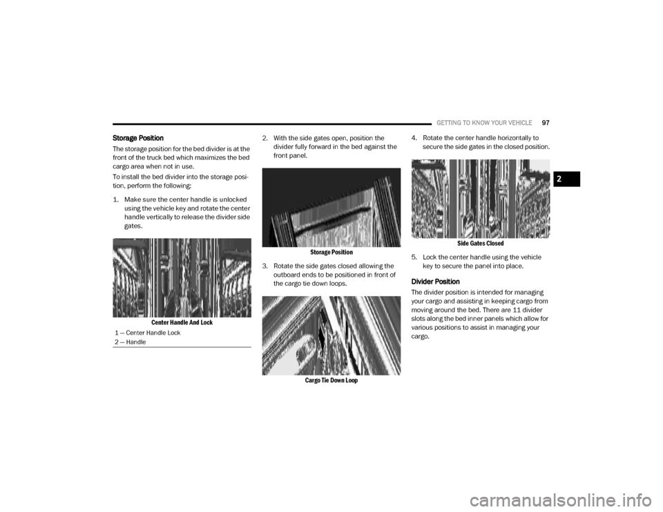
Storage Position
The storage position for the bed divider is at the
front of the truck bed which maximizes the bed
cargo area when not in use.
To install the bed divider into the storage posi -
tion, perform the following:
1. Make sure the center handle is unlocked using the vehicle key and rotate the center
handle vertically to release the divider side
gates.
Center Handle And Lock
2. With the side gates open, position the
divider fully forward in the bed against the
front panel.
Storage Position
3. Rotate the side gates closed allowing the outboard ends to be positioned in front of
the cargo tie down loops.
Cargo Tie Down Loop
4. Rotate the center handle horizontally to
secure the side gates in the closed position.
Side Gates Closed
5. Lock the center handle using the vehicle key to secure the panel into place.
Divider Position
The divider position is intended for managing
your cargo and assisting in keeping cargo from
moving around the bed. There are 11 divider
slots along the bed inner panels which allow for
various positions to assist in managing your
cargo.
1 — Center Handle Lock
2 — Handle
2
20_DJD2_OM_EN_USC_t.book Page 97
Page 100 of 553

98GETTING TO KNOW YOUR VEHICLE
To install the bed divider into a divider position,
perform the following:
1. Make sure the center handle is unlocked
using the vehicle key and rotate the center
handle vertically to release the divider side
gates.
Center Handle And Lock
2. With the side gates open, position the divider so the outboard ends align with the
intended slots in the sides of the bed.
Aligning Gate To Slots
3. Rotate the side gates closed so that the outboard ends are secured into the
intended slots of the bed.
4. Rotate the center handle horizontally to secure the side gates in the closed position.
Side Gates Closed
5. Lock the center handle to secure the panel
into place.
Bed Rail Tie-Down System — If Equipped
NOTE:
This feature is only available for vehicles
equipped with a RamBox.
There are two adjustable cleats on each side of the
bed that can be used to assist in securing cargo.
Adjustable Cleats
1 — Center Handle Lock
2 — Handle
CAUTION!
The maximum load per cleat should not
exceed 250 lbs (113 kg) and the angle of
the load on each cleat should not exceed
45 degrees above horizontal, or damage to
the cleat or cleat rail may occur.
20_DJD2_OM_EN_USC_t.book Page 98