Ram 3500 2020 Owner's Manual
Manufacturer: RAM, Model Year: 2020, Model line: 3500, Model: Ram 3500 2020Pages: 568
Page 421 of 568

SERVICING AND MAINTENANCE419
be used up to ten years or 150,000 miles
(240,000 km) before replacement. To prevent
reducing this extended maintenance period, it
is important that you use the same engine
coolant (OAT coolant conforming to MS.90032)
throughout the life of your vehicle.
Please review these recommendations for
using Organic Additive Technology (OAT) engine
coolant (antifreeze) that meets the
requirements of FCA Material Standard
MS.90032. When adding engine coolant
(antifreeze):
We recommend using Mopar Antifreeze/
Coolant 10 Year/150,000 Mile (240,000 km)
Formula OAT (Organic Additive Technology)
that meets the requirements of FCA Material
Standard MS.90032.
Mix a minimum solution of 50% OAT engine
coolant that meets the requirements of FCA
Material Standard MS.90032 and distilled
water. Use higher concentrations (not to
exceed 70%) if temperatures below −34°F
(−37°C) are anticipated. Please contact an
authorized dealer for assistance.
Use only high purity water such as distilled or
deionized water when mixing the water/
engine coolant (antifreeze) solution. The use
of lower quality water will reduce the amount
of corrosion protection in the engine cooling
system.
NOTE:
It is the owner's responsibility to maintain the
proper level of protection against freezing
according to the temperatures occurring in
the area where the vehicle is operated.
Some vehicles require special tools to add
coolant properly. Failure to fill these systems
properly could lead to severe internal engine
damage. If any coolant is needed to be added
to the system, please contact a local autho -
rized dealer.
Mixing engine coolant (antifreeze) types is
not recommended and can result in cooling
system damage. If HOAT and OAT coolant are
mixed in an emergency, have an authorized
dealer drain, flush, and refill with OAT coolant
(conforming to MS.90032) as soon as
possible.
Cooling System Pressure Cap
The cap must be fully tightened to prevent loss
of engine coolant (antifreeze), and to ensure
that engine coolant (antifreeze) will return to
the radiator from the coolant expansion bottle/
recovery tank if so equipped.
The cap should be inspected and cleaned if
there is any accumulation of foreign material on
the sealing surfaces.
WARNING!
Do not open hot engine cooling system.
Never add engine coolant (antifreeze) when
the engine is overheated. Do not loosen or
remove the cap to cool an overheated
engine. Heat causes pressure to build up in
the cooling system. To prevent scalding or
injury, do not remove the pressure cap
while the system is hot or under pressure.
Do not use a pressure cap other than the
one specified for your vehicle. Personal
injury or engine damage may result.
7
20_DJD2_OM_EN_USC_t.book Page 419
Page 422 of 568

420SERVICING AND MAINTENANCE
Disposal Of Used Coolant
Used ethylene glycol-based coolant (antifreeze) is
a regulated substance requiring proper disposal.
Check with your local authorities to determine the
disposal rules for your community. To prevent
ingestion by animals or children, do not store
ethylene glycol-based coolant in open containers
or allow it to remain in puddles on the ground. If
ingested by a child or pet, seek emergency
assistance immediately. Clean up any ground
spills immediately.
Checking Coolant Level — 6.4L Engine
The level of the coolant in the pressurized coolant
bottle should be between the “MIN” and “MAX”
range on the bottle when the engine is cold.
The radiator normally remains completely full,
so there is no need to remove the cap unless
checking for coolant freeze point or replacing
engine coolant (antifreeze). Advise your service
attendant of this. As long as the engine
operating temperature is satisfactory, the
coolant bottle need only be checked once a
month. When additional engine coolant
(antifreeze) is needed to maintain the proper
level, it should be added to the coolant bottle.
Do not overfill.
Points To Remember
NOTE:
When the vehicle is stopped after a few miles/
kilometers of operation, you may observe vapor
coming from the front of the engine compart -
ment. This is normally a result of moisture from
rain, snow, or high humidity accumulating on
the radiator and being vaporized when the ther -
mostat opens, allowing hot engine coolant (anti -
freeze) to enter the radiator.
If an examination of your engine compartment
shows no evidence of radiator or hose leaks,
the vehicle may be safely driven. The vapor will
soon dissipate.
Do not overfill the coolant expansion bottle.
Check the coolant freeze point in the radiator
and in the coolant expansion bottle. If engine
coolant (antifreeze) needs to be added, the
contents of the coolant expansion bottle
must also be protected against freezing.
If frequent engine coolant (antifreeze) addi-
tions are required, the cooling system should
be pressure tested for leaks.
Maintain engine coolant (antifreeze) concen -
tration at a minimum of 50% OAT coolant
(conforming to MS.90032) and distilled
water for proper corrosion protection of your
engine which contains aluminum compo -
nents.
Make sure that the coolant expansion bottle
overflow hoses are not kinked or obstructed.
Keep the front of the radiator clean. If your
vehicle is equipped with air conditioning,
keep the front of the condenser clean.
Do not change the thermostat for Summer or
Winter operation. If replacement is ever
necessary, install ONLY the correct type ther -
mostat. Other designs may result in unsatis -
factory engine coolant (antifreeze)
performance, poor gas mileage, and
increased emissions.
20_DJD2_OM_EN_USC_t.book Page 420
Page 423 of 568
SERVICING AND MAINTENANCE421
(Continued)
CHARGE AIR COOLER — INTER-COOLER
The charge air cooler is positioned below the
radiator and the air conditioner condenser. Air
enters the engine through the air cleaner and
passes through the turbocharger, where it is
pressurized. This pressurized air rapidly
reaches high temperature. The air is then
directed through a hose to the charge air cooler
and through another hose to the intake
manifold of the engine. The air entering the
engine has been cooled by about 50° to 100°F
(10° to 38°C). This cooling process enables
more efficient burning of fuel resulting in fewer
emissions.
To guarantee optimum performance of the
system, keep the surfaces of the charge air
cooler, condenser and radiator clean and free
of debris. Periodically check the hoses leading
to and from the charge air cooler for cracks or
loose clamps resulting in loss of pressure and
reduced engine performance.
BRAKE SYSTEM
In order to ensure brake system performance,
all brake system components should be
inspected periodically. Refer to the “Maintenance Plan” in this section for the
proper maintenance intervals.
Fluid Level Check — Brake Master Cylinder
The fluid level of the master cylinder should be
checked when performing under the hood
service or immediately if the brake system
warning lamp indicates system failure.
If necessary, add fluid to bring level within the
designated marks on the side of the reservoir of
the brake master cylinder. Be sure to clean the
top of the master cylinder area before removing
cap.
With disc brakes the fluid level can be expected
to fall as the brake linings wear. However, an
unexpected drop in fluid level may be caused by
a leak and a system check should be
conducted.
Refer to “Fluids And Lubricants” in “Technical
Specifications” for further information.
WARNING!
Riding the brakes can lead to brake failure
and possibly a collision. Driving with your foot
resting or riding on the brake pedal can result
in abnormally high brake temperatures,
excessive lining wear, and possible brake
damage. You would not have your full braking
capacity in an emergency.
WARNING!
Use only manufacturer's recommended
brake fluid. Refer to “Fluids And Lubricants”
in “Technical Specifications” for further infor-
mation. Using the wrong type of brake fluid
can severely damage your brake system
and/or impair its performance. The proper
type of brake fluid for your vehicle is also
identified on the original factory installed
hydraulic master cylinder reservoir.
To avoid contamination from foreign matter
or moisture, use only new brake fluid or fluid
that has been in a tightly closed container.
Keep the master cylinder reservoir cap
secured at all times. Brake fluid in a open
container absorbs moisture from the air
resulting in a lower boiling point. This may
cause it to boil unexpectedly during hard or
prolonged braking, resulting in sudden brake
failure. This could result in a collision.
7
20_DJD2_OM_EN_USC_t.book Page 421
Page 424 of 568
422SERVICING AND MAINTENANCE
AUTOMATIC TRANSMISSION
Selection Of Lubricant
It is important to use the proper transmission
fluid to ensure optimum transmission
performance and life. Use only the
manufacturer’s specified transmission fluid.
Refer to “Fluids And Lubricants” in “Technical
Specifications”. It is important to maintain the
transmission fluid at the correct level using the
recommended fluid. No chemical flushes
should be used in any transmission; only the
approved lubricant should be used.
Special Additives
The manufacturer strongly recommends
against using any special additives in the
transmission. Automatic Transmission Fluid
(ATF) is an engineered product and its
performance may be impaired by supplemental
additives. Therefore, do not add any fluid
additives to the transmission. The only
exception to this policy is the use of special dyes
for diagnosing fluid leaks in six-speed
transmissions. Avoid using transmission
sealers as they may adversely affect seals.
Fluid Level Check — Eight-Speed
Transmission
The fluid level is preset at the factory and does
not require adjustment under normal operating
conditions. Routine fluid level checks are not
required, therefore the transmission has no
dipstick. An authorized dealer can check your
transmission fluid level using special service
tools.
If you notice fluid leakage or transmission
malfunction, visit an authorized dealer
immediately to have the transmission fluid level
checked. Operating the vehicle with an
improper fluid level can cause severe
transmission damage.
Overfilling the brake fluid reservoir can
result in spilling brake fluid on hot engine
parts, causing the brake fluid to catch fire.
Brake fluid can also damage painted and
vinyl surfaces, care should be taken to
avoid its contact with these surfaces.
Do not allow petroleum based fluid to
contaminate the brake fluid. Brake seal
components could be damaged, causing
partial or complete brake failure. This could
result in a collision.
WARNING! (Continued)CAUTION!
Using a transmission fluid other than the
manufacturer’s recommended fluid may
cause deterioration in transmission shift
quality and/or torque converter shudder, and
(for six-speed transmissions) will require
more frequent fluid and filter changes. Refer
to “Fluids And Lubricants” in “Technical
Specifications” for fluid specifications.
CAUTION!
Do not use chemical flushes in your
transmission as the chemicals can damage
your transmission components. Such damage
is not covered by the New Vehicle Limited
Warranty.
20_DJD2_OM_EN_USC_t.book Page 422
Page 425 of 568
SERVICING AND MAINTENANCE423
Fluid Level Check — Six-Speed
Transmission
It is best to check the fluid level when the
transmission is at normal operating
temperature (158-176°F / 70-80°C). This
normally occurs after at least 15 miles (25 km)
of driving. At normal operating temperature the
fluid cannot be held comfortably between the
fingertips. You can read the transmission sump
temperature in the instrument cluster screen
refer to “Instrument Cluster Display” in “Getting
To Know Your Instrument Panel” for further
information.
Use the following procedure to check the
transmission fluid level properly:
1. Monitor the transmission temperature using the instrument cluster display, and
operate the vehicle as required to reach
the normal operating temperature. If the transmission is not functioning properly, or
the vehicle cannot be driven, see the NOTE
and CAUTION below about checking the
fluid level at colder temperatures.
2. Park the vehicle on level ground.
3. Run the engine at normal idle speed for at least 60 seconds, and leave the engine
running for the rest of this procedure.
4. Fully apply the parking brake, and press the brake pedal.
5. Place the gear selector momentarily into each gear position (allowing time for the
transmission to fully engage in each
position), ending with the transmission in
PARK.
6. Remove the dipstick, wipe it clean and reinsert it until seated.
7. Remove the dipstick again and note the fluid level on both sides. The fluid level
reading is only valid if there is a solid
coating of oil on both sides of the dipstick.
Note that the holes in the dipstick will be full
of fluid if the actual level is at or above the
hole. The fluid level should be between the
“HOT” (upper) reference holes on the dipstick at normal operating temperature. If
the fluid level is low, add fluid through the
dipstick tube to bring it to the proper level.
Do not overfill.
Use ONLY the specified fluid
refer to "Fluids And Lubricants" in
“Technical Specifications” for fluid specifi -
cations. After adding any quantity of oil
through the dipstick tube, wait a minimum
of two minutes for the oil to fully drain into
the transmission before rechecking the
fluid level.
NOTE:
If it is necessary to check the transmission
below the operating temperature, the fluid level
should be between the two “COLD” (lower)
holes on the dipstick with the fluid at 60-70°F /
16-21°C. Only use the COLD region of the
dipstick as a rough reference when setting the
fluid level after a transmission service or fluid
change. Re-check the fluid level, and adjust as
required, once the transmission reaches
normal operating temperature.
CAUTION!
If a transmission fluid leak occurs, visit an
authorized dealer immediately. Severe
transmission damage may occur. An
authorized dealer has the proper tools to
adjust the fluid level accurately.
7
20_DJD2_OM_EN_USC_t.book Page 423
Page 426 of 568

424SERVICING AND MAINTENANCE
8. Reinsert the dipstick. Check for leaks.
Release the parking brake.
NOTE:
If it is necessary to check the transmission
below the operating temperature, the fluid level
should be between the two COLD (lower) holes
on the dipstick with the fluid at 68-86°F /
20-30°C. Only use the COLD region of the
dipstick as a rough reference when setting the
fluid level after a transmission service or fluid
change. Re-check the fluid level, and adjust as
required, once the transmission reaches
normal operating temperature.
Fluid And Filter Changes — Eight-Speed
Transmission
Under normal operating conditions, the fluid
installed at the factory will provide satisfactory
lubrication for the life of the vehicle.
Routine fluid and filter changes are not
required. However, change the fluid and filter if
the fluid becomes contaminated (with water,
etc.), or if the transmission is disassembled for
any reason.
Fluid And Filter Changes — Six Speed
Transmission
Refer to the “Maintenance Plan” for the proper
maintenance intervals.
In addition, change the fluid and filters if the
fluid becomes contaminated (with water, etc.),
or if the transmission is disassembled for any
reason.
REAR AXLE AND 4X4 FRONT DRIVING
A
XLE FLUID LEVEL
For normal service, periodic fluid level checks
are not required. When the vehicle is serviced
for other reasons the exterior surfaces of the
axle assembly should be inspected. If gear oil
leakage is suspected inspect the fluid level. Refer to “Fluids And Lubricants” in “Technical
Specifications” for further information. This
inspection should be made with the vehicle in a
level position.
For all 2500/3500 Model axles, the fluid level
should be 1/4 in ± 1/4 in (6.4 mm ± 6.4 mm)
below the fill hole on the 9.25 in front, 11.5 in
rear axle, and 12.0 in rear axle.
Drain And Refill
Refer to the “Maintenance Plan” for the proper
maintenance intervals.
Lubricant Selection
Refer to “Fluids And Lubricants” in “Technical
Specifications” for further information.
NOTE:
The presence of water in the gear lubricant will
result in corrosion and possible failure of differ -
ential components. Operation of the vehicle in
water, as may be encountered in some
off-highway types of service, will require
draining and refilling the axle to avoid damage.
Limited-Slip Differentials DO REQUIRE limited
slip oil additive (friction modifiers).
CAUTION!
If the fluid temperature is below 50°F (10°C)
it may not register on the dipstick. Do not add
fluid until the temperature is elevated enough
to produce an accurate reading. Run the
engine at idle, in PARK, to warm the fluid.
CAUTION!
If the fluid temperature is below 50°F (10°C)
it may not register on the dipstick. Do not add
fluid until the temperature is elevated enough
to produce an accurate reading. Run the
engine at idle, in PARK, to warm the fluid.
20_DJD2_OM_EN_USC_t.book Page 424
Page 427 of 568
SERVICING AND MAINTENANCE425
NOTE:
Slight noise and mild shuddering may be
evident while turning a vehicle with limited slip
differential on concrete or dry pavement. These
conditions should be considered normal opera -
tion of the limited slip differential.
TRANSFER CASE
Selection Of Lubricant
Use only the manufacturer's recommended
fluid. Refer to “Fluids And Lubricants” in
“Technical Specifications” for further
information.
Fluid Level Check
This fluid level can be checked by removing the
filler plug. The fluid level should be to the
bottom edge of the filler plug hole with the
vehicle in a level position.
Drain And Refill
Refer to the “Maintenance Plan” in this section
for the proper maintenance intervals.
NOISE CONTROL SYSTEM REQUIRED
M
AINTENANCE & WARRANTY
All vehicles built over 10,000 lbs. (4,535 kg)
Gross Vehicle Weight Rating and manufactured
for sale and use in the United States are
required to comply with the Federal
Government's Exterior Noise Regulations.
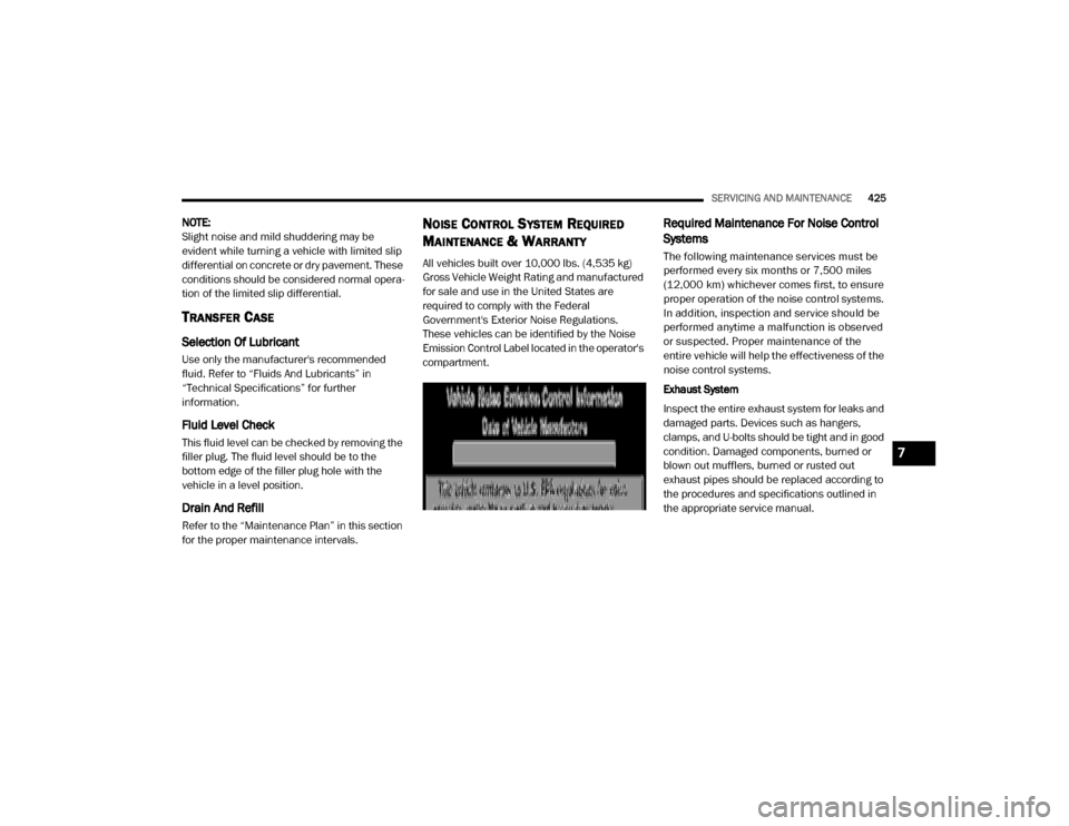
These vehicles can be identified by the Noise
Emission Control Label located in the operator's
compartment.
Required Maintenance For Noise Control
Systems
The following maintenance services must be
performed every six months or 7,500 miles
(12,000 km) whichever comes first, to ensure
proper operation of the noise control systems.
In addition, inspection and service should be
performed anytime a malfunction is observed
or suspected. Proper maintenance of the
entire vehicle will help the effectiveness of the
noise control systems.
Exhaust System
Inspect the entire exhaust system for leaks and
damaged parts. Devices such as hangers,
clamps, and U-bolts should be tight and in good
condition. Damaged components, burned or
blown out mufflers, burned or rusted out
exhaust pipes should be replaced according to
the procedures and specifications outlined in
the appropriate service manual.
7
20_DJD2_OM_EN_USC_t.book Page 425
Page 428 of 568

426SERVICING AND MAINTENANCE
Air Cleaner Assembly
Inspect air cleaner housing for proper assembly
and fit. Make certain that the air cleaner is
properly positioned and that the cover is tight.
Check all hoses leading to the air cleaner for
tightness. The air filter element must also be
clean and serviced according to the instructions
outlined in the Scheduled Maintenance section
of this manual.
Tampering With Noise Control System
Prohibited
Federal law prohibits the following acts or the
causing thereof: (1) the removal or rendering
inoperative by any person, other than for
purposes of maintenance, repair, or
replacement, of any device or element of design
incorporated into any new vehicle for the
purpose of noise control prior to its sale or
delivery to the ultimate purchaser or while it is
in use, or (2) the use of the vehicle after such
device or element of design has been removed
or rendered inoperative by any person. Among those acts presumed to constitute
tampering are the acts listed below.
AIR CLEANER
Removal of the air cleaner.
Removal of the air cleaner filter element from
the air cleaner housing.
Removal of the air ducting.
EXHAUST SYSTEM
Removal or rendering inoperative exhaust
system components including the muffler or
tailpipe.
ENGINE COOLING SYSTEM
Removal or rendering inoperative the fan
clutch.
Removal of the fan shroud.
Noise Emission Warranty
The manufacturer warrants that this vehicle as
manufactured by the manufacturer, was
designed, built and equipped to conform at the
time it left the manufacturer's control with all
applicable U.S. EPA Noise Control Regulations.
This warranty covers this vehicle as designed,
built and equipped by the manufacturer, and is
not limited to any particular part, component or
system of the vehicle manufactured by the
manufacturer. Defects in design, assembly or in
any part, component or system of the vehicle as
manufactured by the manufacturer, which, at
the time it left the manufacturer's control,
caused noise emissions to exceed Federal
standards, are covered by this warranty for the
life of the vehicle.
20_DJD2_OM_EN_USC_t.book Page 426
Page 429 of 568
SERVICING AND MAINTENANCE427
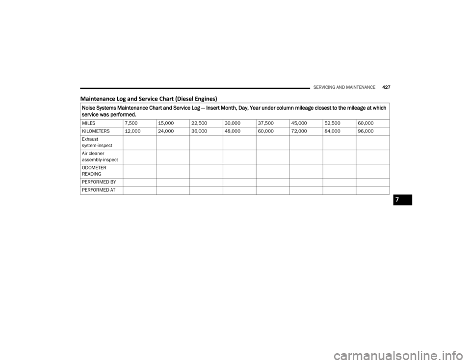
Maintenance Log and Service Chart (Diesel Engines)
Noise Systems Maintenance Chart and Service Log — Insert Month, Day, Year under column mileage closest to the mileage at which
service was performed.
MILES7,500 15,000 22,500 30,000 37,500 45,000 52,500 60,000
KILOMETERS 12,000 24,000 36,000 48,000 60,000 72,000 84,000 96,000
Exhaust
system-inspect
Air cleaner
assembly-inspect
ODOMETER
READING
PERFORMED BY
PERFORMED AT
7
20_DJD2_OM_EN_USC_t.book Page 427
Page 430 of 568
428SERVICING AND MAINTENANCE
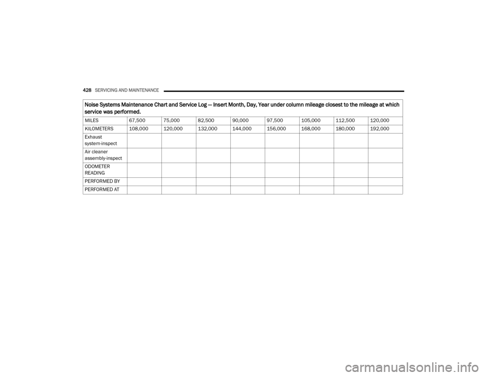
MILES67,500 75,000 82,500 90,000 97,500 105,000 112,500 120,000
KILOMETERS 108,000 120,000 132,000 144,000 156,000 168,000 180,000 192,000
Exhaust
system-inspect
Air cleaner
assembly-inspect
ODOMETER
READING
PERFORMED BY
PERFORMED AT
Noise Systems Maintenance Chart and Service Log — Insert Month, Day, Year under column mileage closest to the mileage at which
service was performed.
20_DJD2_OM_EN_USC_t.book Page 428