Ram 3500 2020 Service Manual
Manufacturer: RAM, Model Year: 2020, Model line: 3500, Model: Ram 3500 2020Pages: 568
Page 41 of 568
GETTING TO KNOW YOUR VEHICLE39
NOTE:
Do not reverse the head restraints (making the
rear of the head restraint face forward) in an
attempt to gain additional clearance to the back
of your head.
FRONT HEAD RESTRAINTS
Four-Way Head Restraints — If Equipped
Your vehicle may be equipped with front
four-way driver and passenger head restraints.
To raise the head restraint, pull upward on the
head restraint. To lower the head restraint,
push the adjustment button, located at the base of the head restraint, and push downward
on the head restraint.
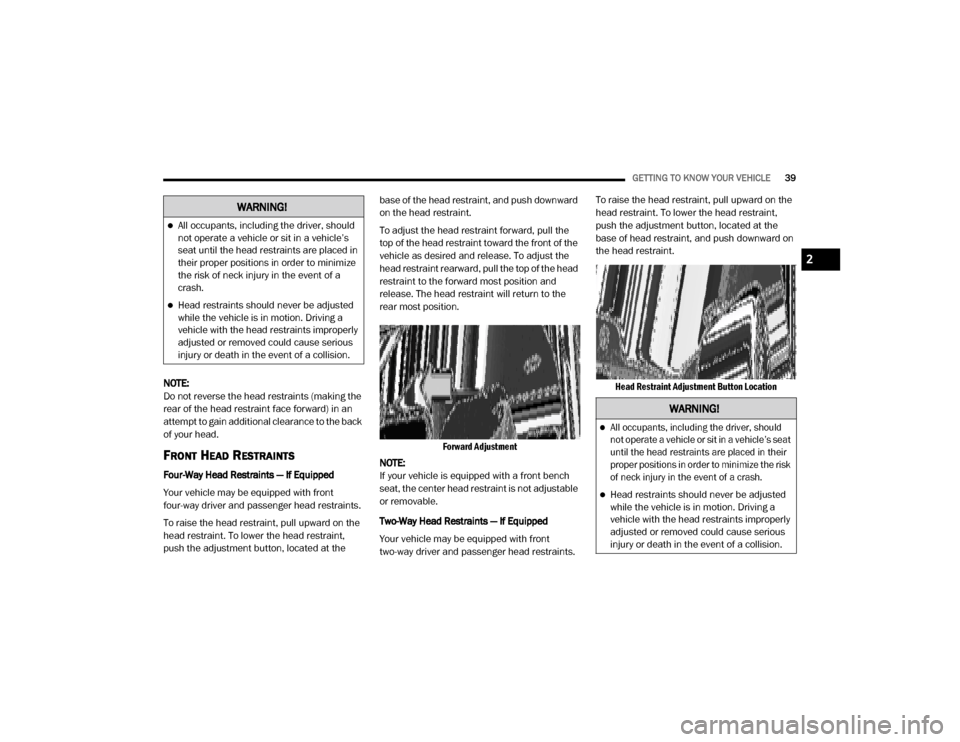
To adjust the head restraint forward, pull the
top of the head restraint toward the front of the
vehicle as desired and release. To adjust the
head restraint rearward, pull the top of the head
restraint to the forward most position and
release. The head restraint will return to the
rear most position.
Forward Adjustment
NOTE:
If your vehicle is equipped with a front bench
seat, the center head restraint is not adjustable
or removable.
Two-Way Head Restraints — If Equipped
Your vehicle may be equipped with front
two-way driver and passenger head restraints. To raise the head restraint, pull upward on the
head restraint. To lower the head restraint,
push the adjustment button, located at the
base of head restraint, and push downward on
the head restraint.
Head Restraint Adjustment Button Location
WARNING!
All occupants, including the driver, should
not operate a vehicle or sit in a vehicle’s
seat until the head restraints are placed in
their proper positions in order to minimize
the risk of neck injury in the event of a
crash.
Head restraints should never be adjusted
while the vehicle is in motion. Driving a
vehicle with the head restraints improperly
adjusted or removed could cause serious
injury or death in the event of a collision.
WARNING!
All occupants, including the driver, should
not operate a vehicle or sit in a vehicle’s seat
until the head restraints are placed in their
proper positions in order to minimize the risk
of neck injury in the event of a crash.
Head restraints should never be adjusted
while the vehicle is in motion. Driving a
vehicle with the head restraints improperly
adjusted or removed could cause serious
injury or death in the event of a collision.
2
20_DJD2_OM_EN_USC_t.book Page 39
Page 42 of 568
40GETTING TO KNOW YOUR VEHICLE
FRONT HEAD RESTRAINT REMOVAL
To remove the head restraint, push the
adjustment button and the release button while
pulling upward on the whole assembly. To
reinstall the head restraint, put the head
restraint posts into the holes and adjust it to the
appropriate height.
REAR HEAD RESTRAINT ADJUSTMENT
The rear seats are equipped with adjustable
and removable head restraints. To raise the
head restraint, pull upward on the head
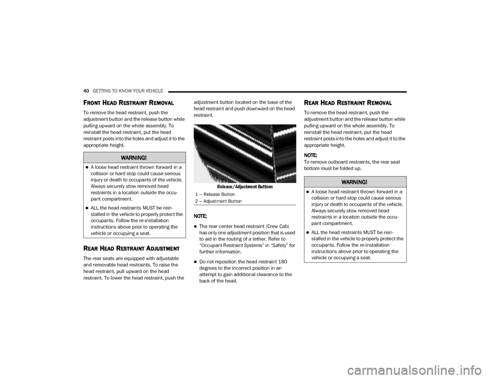
restraint. To lower the head restraint, push the adjustment button located on the base of the
head restraint and push downward on the head
restraint.
Release/Adjustment Buttons
NOTE:
The rear center head restraint (Crew Cab)
has only one adjustment position that is used
to aid in the routing of a tether. Refer to
“Occupant Restraint Systems” in “Safety” for
further information.
Do not reposition the head restraint 180
degrees to the incorrect position in an
attempt to gain additional clearance to the
back of the head.
REAR HEAD RESTRAINT REMOVAL
To remove the head restraint, push the
adjustment button and the release button while
pulling upward on the whole assembly. To
reinstall the head restraint, put the head
restraint posts into the holes and adjust it to the
appropriate height.
NOTE:
To remove outboard restraints, the rear seat
bottom must be folded up.
WARNING!
A loose head restraint thrown forward in a
collision or hard stop could cause serious
injury or death to occupants of the vehicle.
Always securely stow removed head
restraints in a location outside the occu -
pant compartment.
ALL the head restraints MUST be rein -
stalled in the vehicle to properly protect the
occupants. Follow the re-installation
instructions above prior to operating the
vehicle or occupying a seat.
1 — Release Button
2 — Adjustment Button
WARNING!
A loose head restraint thrown forward in a
collision or hard stop could cause serious
injury or death to occupants of the vehicle.
Always securely stow removed head
restraints in a location outside the occu -
pant compartment.
ALL the head restraints MUST be rein -
stalled in the vehicle to properly protect the
occupants. Follow the re-installation
instructions above prior to operating the
vehicle or occupying a seat.
20_DJD2_OM_EN_USC_t.book Page 40
Page 43 of 568
GETTING TO KNOW YOUR VEHICLE41
STEERING WHEEL
TILT STEERING COLUMN
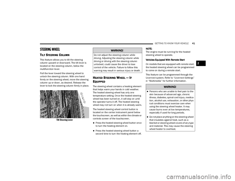
This feature allows you to tilt the steering
column upward or downward. The tilt lever is
located on the steering column, below the
multifunction lever.
Pull the lever toward the steering wheel to
unlock the steering column. With one hand
firmly on the steering wheel, move the steering
column up or down, as desired. Release the
lever to lock the steering column firmly in place.
Tilt Steering Lever
HEATED STEERING WHEEL — IF
E
QUIPPED
The steering wheel contains a heating element
that helps warm your hands in cold weather.
The heated steering wheel has only one
temperature setting. Once the heated steering
wheel has been turned on, it will stay on until
the operator turns it off. The heated steering
wheel may not turn on when it is already warm.
The heated steering wheel control button is
located on the center instrument panel below
the touchscreen, as well as within the climate or
controls screen of the touchscreen.
Press the heated steering wheel button once
to turn the heating element on.
Press the heated steering wheel button a
second time to turn the heating element off. NOTE:
The engine must be running for the heated
steering wheel to operate.
Vehicles Equipped With Remote Start
On models that are equipped with remote start,
the heated steering wheel can be programmed
to come on during a remote start.
This feature can be programmed through the
Uconnect system. Refer to “Uconnect Settings”
in “Multimedia” for further information.
WARNING!
Do not adjust the steering column while
driving. Adjusting the steering column while
driving or driving with the steering column
unlocked, could cause the driver to lose
control of the vehicle. Failure to follow this
warning may result in serious injury or death.
WARNING!
Persons who are unable to feel pain to the
skin because of advanced age, chronic
illness, diabetes, spinal cord injury, medica
-
tion, alcohol use, exhaustion, or other phys -
ical conditions must exercise care when
using the steering wheel heater. It may
cause burns even at low temperatures,
especially if used for long periods.
Do not place anything on the steering wheel
that insulates against heat, such as a
blanket or steering wheel covers of any type
and material. This may cause the steering
wheel heater to overheat.
2
20_DJD2_OM_EN_USC_t.book Page 41
Page 44 of 568
42GETTING TO KNOW YOUR VEHICLE
DRIVER ADJUSTABLE PEDALS — IF
EQUIPPED
The adjustable pedals system is designed to
allow a greater range of driver comfort for
steering wheel tilt and seat position. This
feature allows the brake and accelerator pedals
to move toward or away from the driver to
provide improved position with the steering
wheel.
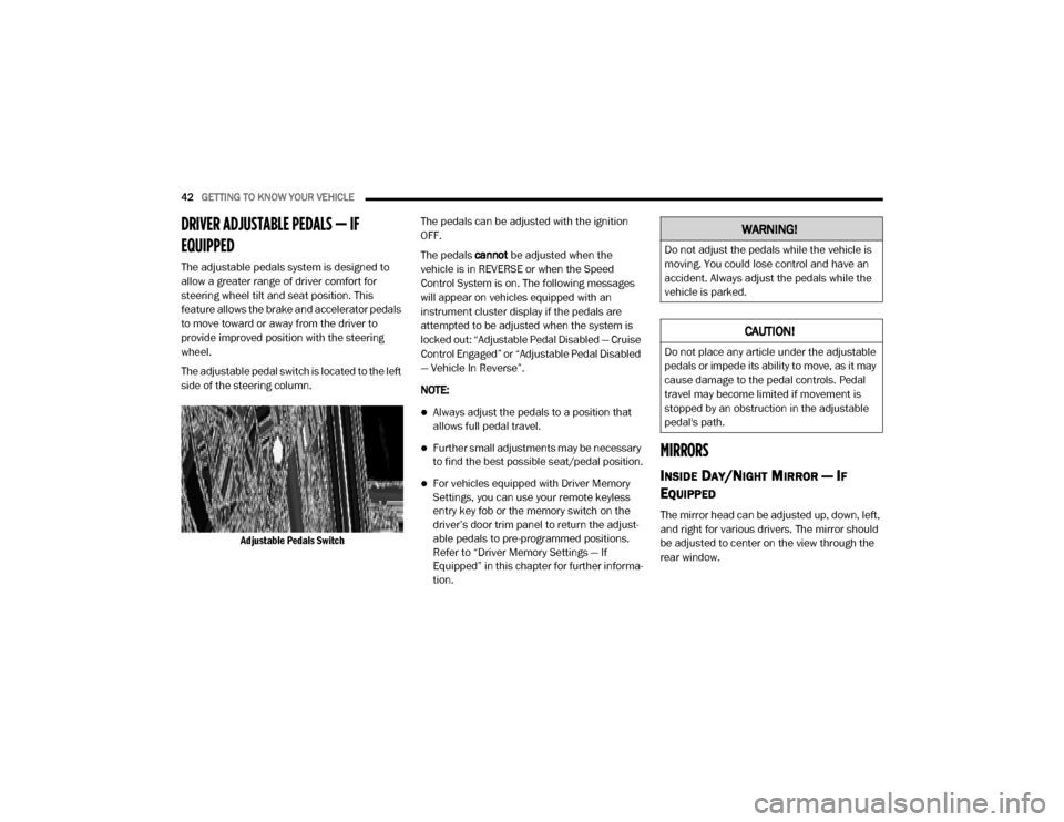
The adjustable pedal switch is located to the left
side of the steering column.
Adjustable Pedals Switch
The pedals can be adjusted with the ignition
OFF.
The pedals
cannot be adjusted when the
vehicle is in REVERSE or when the Speed
Control System is on. The following messages
will appear on vehicles equipped with an
instrument cluster display if the pedals are
attempted to be adjusted when the system is
locked out: “Adjustable Pedal Disabled — Cruise
Control Engaged” or “Adjustable Pedal Disabled
— Vehicle In Reverse”.
NOTE:
Always adjust the pedals to a position that
allows full pedal travel.
Further small adjustments may be necessary
to find the best possible seat/pedal position.
For vehicles equipped with Driver Memory
Settings, you can use your remote keyless
entry key fob or the memory switch on the
driver’s door trim panel to return the adjust -
able pedals to pre-programmed positions.
Refer to “Driver Memory Settings — If
Equipped” in this chapter for further informa -
tion.
MIRRORS
INSIDE DAY/NIGHT MIRROR — IF
E
QUIPPED
The mirror head can be adjusted up, down, left,
and right for various drivers. The mirror should
be adjusted to center on the view through the
rear window.
WARNING!
Do not adjust the pedals while the vehicle is
moving. You could lose control and have an
accident. Always adjust the pedals while the
vehicle is parked.
CAUTION!
Do not place any article under the adjustable
pedals or impede its ability to move, as it may
cause damage to the pedal controls. Pedal
travel may become limited if movement is
stopped by an obstruction in the adjustable
pedal's path.
20_DJD2_OM_EN_USC_t.book Page 42
Page 45 of 568
GETTING TO KNOW YOUR VEHICLE43
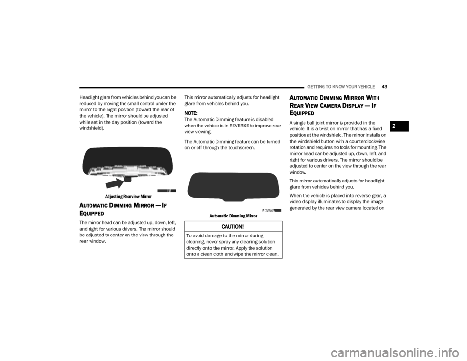
Headlight glare from vehicles behind you can be
reduced by moving the small control under the
mirror to the night position (toward the rear of
the vehicle). The mirror should be adjusted
while set in the day position (toward the
windshield).
Adjusting Rearview Mirror
AUTOMATIC DIMMING MIRROR — IF
E
QUIPPED
The mirror head can be adjusted up, down, left,
and right for various drivers. The mirror should
be adjusted to center on the view through the
rear window. This mirror automatically adjusts for headlight
glare from vehicles behind you.
NOTE:
The Automatic Dimming feature is disabled
when the vehicle is in REVERSE to improve rear
view viewing.
The Automatic Dimming feature can be turned
on or off through the touchscreen.
Automatic Dimming Mirror
AUTOMATIC DIMMING MIRROR WITH
R
EAR VIEW CAMERA DISPLAY — IF
E
QUIPPED
A single ball joint mirror is provided in the
vehicle. It is a twist on mirror that has a fixed
position at the windshield. The mirror installs on
the windshield button with a counterclockwise
rotation and requires no tools for mounting. The
mirror head can be adjusted up, down, left, and
right for various drivers. The mirror should be
adjusted to center on the view through the rear
window.
This mirror automatically adjusts for headlight
glare from vehicles behind you.
When the vehicle is placed into reverse gear, a
video display illuminates to display the image
generated by the rear view camera located on
CAUTION!
To avoid damage to the mirror during
cleaning, never spray any cleaning solution
directly onto the mirror. Apply the solution
onto a clean cloth and wipe the mirror clean.
2
20_DJD2_OM_EN_USC_t.book Page 43
Page 46 of 568

44GETTING TO KNOW YOUR VEHICLE
the tailgate handle. The auto dimming feature is
also disabled to improve rear view viewing.
Automatic Dimming Mirror With Rear View Camera
OUTSIDE MIRRORS
To receive maximum benefit, adjust the outside
mirrors to center on the adjacent lane of traffic
with a slight overlap of the view obtained on the
inside mirror.
NOTE:
If your vehicle is equipped with puddle lamps
under the outside mirrors, they can be turned off through the Uconnect display. For further
information, refer to “Uconnect Settings” in
“Multimedia”.
DRIVER'S OUTSIDE AUTOMATIC
D
IMMING MIRROR — IF EQUIPPED
The driver’s outside mirror will automatically
adjust for glare from vehicles behind you. This
feature is controlled by the inside automatic dimming mirror and will automatically adjust for
headlight glare when the inside mirror adjusts.
POWER MIRRORS — IF EQUIPPED
The controls for the power mirrors are located
on the driver's door trim panel.
Power Mirror Controls
WARNING!
Vehicles and other objects seen in the
passenger side convex mirror will look smaller
and farther away than they really are. Relying
too much on your passenger side convex
mirror could cause you to collide with another
vehicle or other object. Use your inside mirror
when judging the size or distance of a vehicle
seen in the passenger side convex mirror.
Some vehicles will not have a convex
passenger side mirror.
1 — Mirror Direction Control
2 — Right Mirror Selection
3 — Left Mirror Selection
20_DJD2_OM_EN_USC_t.book Page 44
Page 47 of 568
GETTING TO KNOW YOUR VEHICLE45
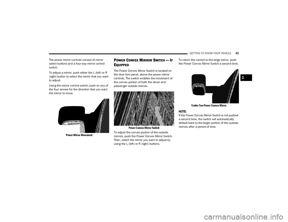
The power mirror controls consist of mirror
select buttons and a four-way mirror control
switch.
To adjust a mirror, push either the L (left) or R
(right) button to select the mirror that you want
to adjust.
Using the mirror control switch, push on any of
the four arrows for the direction that you want
the mirror to move.
Power Mirror Movement
POWER CONVEX MIRROR SWITCH — IF
E
QUIPPED
The Power Convex Mirror Switch is located on
the door trim panel, above the power mirror
controls. The switch enables the movement of
the convex portion of both the driver and
passenger outside mirrors.
Power Convex Mirror Switch
To adjust the convex portion of the outside
mirrors, push the Power Convex Mirror Switch.
Then, select the mirror you want to adjust by
using the L (left) or R (right) buttons. To return the control to the large mirror, push
the Power Convex Mirror Switch a second time.
Trailer Tow Power Convex Mirror
NOTE:
If the Power Convex Mirror Switch is not pushed
a second time, the switch will automatically
default back to the larger portion of the outside
mirrors after a period of time.
2
20_DJD2_OM_EN_USC_t.book Page 45
Page 48 of 568

46GETTING TO KNOW YOUR VEHICLE
TRAILER TOWING MIRRORS — IF
E
QUIPPED
These mirrors are designed with an adjustable
mirror head to provide a greater vision range
when towing extra-wide loads. To change
position inboard or outboard, the mirror head
should be rotated (flipped in or out).
Trailer Towing Position
NOTE:
Fold the trailer towing mirrors rearward prior to
entering an automated car wash.
A small blindspot mirror is located next to main
mirror and can be adjusted separately.
Blindspot Mirror
HEATED MIRRORS — IF EQUIPPED
These mirrors are heated to melt frost
or ice. This feature will be activated
whenever you turn on the rear window
defroster (if equipped).
Refer to “Climate Controls” in this chapter for
further information.
TILT SIDE MIRRORS IN REVERSE — IF
E
QUIPPED
Tilt Side Mirrors In Reverse provides automatic
outside mirror positioning which will aid the
driver’s view of the ground rearward of the front
doors. The outside mirrors will move slightly
downward from the present position when the
vehicle is shifted into REVERSE. The outside mirrors will then return to the original position
when the vehicle is shifted out of the REVERSE
position. Each stored memory setting will have
an associated Tilt Side Mirrors In Reverse
position.
NOTE:
The Tilt Side Mirrors In Reverse feature is not
turned on when delivered from the factory.
This feature can be programmed through the
Uconnect system. Refer to “Uconnect Settings”
in “Multimedia” for further information.
POWER FOLDING OUTSIDE MIRRORS
F
OR STANDARD AND TRAILER TOW — IF
E
QUIPPED
If equipped with power folding mirrors, they can
be electrically folded rearward and unfolded
into the drive position.
The switch for the power folding mirrors is
located between the power mirror switches L
(left) and R (right). Push the switch once and the
mirrors will fold in, push the switch a second
time and the mirrors will return to the normal
driving position.
20_DJD2_OM_EN_USC_t.book Page 46
Page 49 of 568

GETTING TO KNOW YOUR VEHICLE47
If the mirror is manually folded after electrically
cycled, a potential extra button push is required
to get the mirrors back to the home position. If
the mirror does not electrically fold, check for
ice or dirt build up at the pivot area which can
cause excessive drag.
Power Folding Mirror Switch
Resetting The Power Folding Outside Mirrors
You may need to reset the power folding mirrors
if the following occurs:
The mirrors are accidentally blocked while
folding.
The mirrors are accidentally manually
folded/unfolded.
The mirrors come out of the unfolded posi -
tion.
The mirrors shake and vibrate at normal
driving speeds.
To Reset The Power Folding Mirrors:
1. Using the power folding mirror switch, move the mirror to its normal driving
(home) position.
2. Using the power folding mirror switch, move the mirror to the full retract position (this
may require multiple button pushes). This
resets them to their normal position.
NOTE:
The power fold mirrors are designed to
operate while the vehicle is stationary or trav -
eling at moderate speeds. If you attempt to
power fold the mirrors at high speeds they
may not fully open or close. You should slow
down to a moderate speed and complete the
operation.
When pushing the power fold button 10 or
more times in one minute the system shuts
down for one minute to protect the motors
from overheating.
Outside Mirrors Folding Feature
All outside mirrors are designed to be able to be
manually folded both forward and rearward to
prevent damage.
Folding Mirror
CAUTION!
It is recommended to fold the mirrors into the
full rearward position to resist damage when
entering a car wash or a narrow location.
2
20_DJD2_OM_EN_USC_t.book Page 47
Page 50 of 568

48GETTING TO KNOW YOUR VEHICLE
ILLUMINATED VANITY MIRROR — IF
E
QUIPPED
Illuminated vanity mirrors are located on each
sun visor. To use the mirror, rotate the sun visor
down and swing the mirror cover upward. The
lights will turn on automatically. Closing the
mirror cover turns off the light.
Lift Cover For Illuminated Mirror
“Slide-On-Rod” Features Of Sun Visor — If
Equipped
The sun visor “Slide-On-Rod” feature allows for
additional flexibility in positioning the visor to
block out the sun.
To use the “Slide-On-Rod” feature, rotate the
sun visor downward and unclip it. Pull the sun
visor along the “Slide-On-Rod” until the sun
visor is in the desired position.
“Slide-On-Rod” Extender
EXTERIOR LIGHTS
MULTIFUNCTION LEVER
The multifunction lever is located on the left
side of the steering column.
Multifunction Lever
HEADLIGHT SWITCH
The headlight switch is located on the left side
of the instrument panel. This switch controls the
operation of the headlights, parking lights,
automatic headlights (if equipped), instrument
panel light dimming, cargo light/trailer spotter
lights (if equipped), and fog lights (if equipped).
Headlight Switch
1 — Rotate Headlight Control
2 — Ambient Light Dimmer Control
3 — Instrument Panel Light Dimmer Control
4 — Push Cargo Light Control
5 — Push Front Fog Light Control
20_DJD2_OM_EN_USC_t.book Page 48