display Ram 3500 2020 Service Manual
[x] Cancel search | Manufacturer: RAM, Model Year: 2020, Model line: 3500, Model: Ram 3500 2020Pages: 568
Page 131 of 568

GETTING TO KNOW YOUR INSTRUMENT PANEL129
demanding hot or high altitude conditions. If the
instrument cluster display displays the
message “Active Airbox Service Required See
Dealer”, vehicle performance may be reduced
until service is performed by an authorized RAM
dealer.
BATTERY SAVER ON/BATTERY SAVER
M
ODE MESSAGE — ELECTRICAL LOAD
R
EDUCTION ACTIONS — IF EQUIPPED
This vehicle is equipped with an Intelligent
Battery Sensor (IBS) to perform additional
monitoring of the electrical system and status
of the vehicle battery.
In cases when the IBS detects charging system
failure, or the vehicle battery conditions are
deteriorating, electrical load reduction actions
will take place to extend the driving time and
distance of the vehicle. This is done by reducing
power to or turning off non-essential electrical
loads.
Load reduction is only active when the engine is
running. It will display a message if there is a
risk of battery depletion to the point where the
vehicle may stall due to lack of electrical supply,
or will not restart after the current drive cycle. When load reduction is activated, the message
“Battery Saver On Some Systems May Have
Reduced Power” will appear in the instrument
cluster.
These messages indicate the vehicle battery
has a low state of charge and continues to lose
electrical charge at a rate that the charging
system cannot sustain.
NOTE:The charging system is independent from
load reduction. The charging system
performs a diagnostic on the charging
system continuously.
If the Battery Charge Warning Light is on it
may indicate a problem with the charging
system. Refer to “Warning Lights And
Messages” in “Getting To Know Your Instru
-
ment Panel” for further information.
The electrical loads that may be switched off (if
equipped), and vehicle functions which can be
affected by load reduction:
Heated Seats/Vented Seats/Heated Wheel
Rear Defroster And Heated Mirrors
HVAC System
115 Volts AC Power Inverter System
Audio and Telematics System
Loss of the battery charge may indicate one or
more of the following conditions:
The charging system cannot deliver enough
electrical power to the vehicle system
because the electrical loads are larger than
the capability of charging system. The
charging system is still functioning properly.
Turning on all possible vehicle electrical
loads (e.g. HVAC to max settings, exterior and
interior lights, overloaded power outlets
+12 Volts, 115 Volts AC, USB ports) during
certain driving conditions (city driving,
towing, frequent stopping).
Installing options like additional lights,
upfitter electrical accessories, audio
systems, alarms and similar devices.
Unusual driving cycles (short trips separated
by long parking periods).
The vehicle was parked for an extended
period of time (weeks, months).
3
20_DJD2_OM_EN_USC_t.book Page 129
Page 132 of 568
130GETTING TO KNOW YOUR INSTRUMENT PANEL
The battery was recently replaced and was
not charged completely.
The battery was discharged by an electrical
load left on when the vehicle was parked.
The battery was used for an extended period
with the engine not running to supply radio,
lights, chargers, +12 Volts portable appli-
ances like vacuum cleaners, game consoles
and similar devices.
What to do when an electrical load reduction
action message is present (“Battery Saver On”
or “Battery Saver Mode”)
During a trip:
Reduce power to unnecessary loads if
possible:
Turn off redundant lights (interior or
exterior).
Check what may be plugged in to power
outlets +12 Volts, 115 Volts AC, USB
ports.
Check HVAC settings (blower, tempera -
ture).
Check the audio settings (volume). After a trip:
Check if any aftermarket equipment was
installed (additional lights, upfitter electrical
accessories, audio systems, alarms) and
review specifications if any (load and Ignition
Off Draw currents).
Evaluate the latest driving cycles (distance,
driving time and parking time).
The vehicle should have service performed if
the message is still present during consecu
-
tive trips and the evaluation of the vehicle
and driving pattern did not help to identify the
cause.
WARNING LIGHTS AND MESSAGES
The warning/indicator lights will illuminate in
the instrument panel together with a dedicated
message and/or acoustic signal when
applicable. These indications are indicative and
precautionary and as such must not be
considered as exhaustive. Always refer to the
information in this chapter in the event of a
failure indication. All active telltales will display
first if applicable. The system check menu may
appear different based upon equipment
options and current vehicle status. Some
telltales are optional and may not appear.
RED WARNING LIGHTS
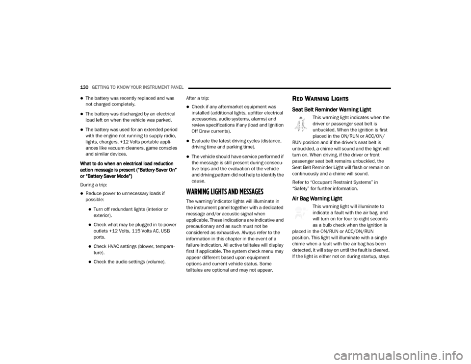
Seat Belt Reminder Warning Light
This warning light indicates when the
driver or passenger seat belt is
unbuckled. When the ignition is first
placed in the ON/RUN or ACC/ON/
RUN position and if the driver’s seat belt is
unbuckled, a chime will sound and the light will
turn on. When driving, if the driver or front
passenger seat belt remains unbuckled, the
Seat Belt Reminder Light will flash or remain on
continuously and a chime will sound.
Refer to “Occupant Restraint Systems” in
“Safety” for further information.
Air Bag Warning Light
This warning light will illuminate to
indicate a fault with the air bag, and
will turn on for four to eight seconds
as a bulb check when the ignition is
placed in the ON/RUN or ACC/ON/RUN
position. This light will illuminate with a single
chime when a fault with the air bag has been
detected, it will stay on until the fault is cleared.
If the light is either not on during startup, stays
20_DJD2_OM_EN_USC_t.book Page 130
Page 138 of 568
136GETTING TO KNOW YOUR INSTRUMENT PANEL
Trailer Merge Assist Indicator Light — If
Equipped
This indicator light will illuminate to
indicate when Trailer Merge Assist
has been activated.
Refer to “Blind Spot Monitoring (BSM)” in
“Safety” for further information.
Tire Pressure Monitoring System (TPMS)
Warning Light
The warning light switches on and a
message is displayed to indicate that
the tire pressure is lower than the
recommended value and/or that slow
pressure loss is occurring. In these cases,
optimal tire duration and fuel consumption may
not be guaranteed.
Should one or more tires be in the condition
mentioned above, the display will show the
indications corresponding to each tire. Each tire, including the spare (if provided),
should be checked monthly when cold and
inflated to the inflation pressure recommended
by the vehicle manufacturer on the vehicle
placard or tire inflation pressure label. If your
vehicle has tires of a different size than the size
indicated on the vehicle placard or tire inflation
pressure label, you should determine the
proper tire inflation pressure for those tires.
As an added safety feature, your vehicle has
been equipped with a Tire Pressure Monitoring
System (TPMS) that illuminates a low tire
pressure telltale when one or more of your tires
is significantly under-inflated. Accordingly, when
the low tire pressure telltale illuminates, you
should stop and check your tires as soon as
possible, and inflate them to the proper
pressure. Driving on a significantly
under-inflated tire causes the tire to overheat
and can lead to tire failure. Under-inflation also
reduces fuel efficiency and tire tread life, and
may affect the vehicle’s handling and stopping
ability.
Please note that the TPMS is not a substitute for
proper tire maintenance, and it is the driver’s
responsibility to maintain correct tire pressure, even if under-inflation has not reached the level
to trigger illumination of the TPMS low tire
pressure telltale.
Your vehicle has also been equipped with a
TPMS malfunction indicator to indicate when
the system is not operating properly. The TPMS
malfunction indicator is combined with the low
tire pressure telltale. When the system detects
a malfunction, the telltale will flash for
approximately one minute and then remain
continuously illuminated. This sequence will
continue upon subsequent vehicle start-ups as
long as the malfunction exists. When the
malfunction indicator is illuminated, the system
may not be able to detect or signal low tire
pressure as intended. TPMS malfunctions may
occur for a variety of reasons, including the
installation of replacement or alternate tires or
wheels on the vehicle that prevent the TPMS
from functioning properly. Always check the
TPMS malfunction telltale after replacing one or
more tires or wheels on your vehicle to ensure
that the replacement or alternate tires and
wheels allow the TPMS to continue to function
properly.
CAUTION!
Do not continue driving with one or more flat
tires as handling may be compromised. Stop the
vehicle, avoiding sharp braking and steering. If a
tire puncture occurs, repair immediately using
the dedicated tire repair kit and contact an
authorized dealer as soon as possible.
20_DJD2_OM_EN_USC_t.book Page 136
Page 140 of 568

138GETTING TO KNOW YOUR INSTRUMENT PANEL
YELLOW INDICATOR LIGHTS
Forward Collision Warning Off Indicator
Light — If Equipped
This indicator light illuminates to
indicate that Forward Collision
Warning is off.
Refer to “Auxiliary Driving Systems” in “Safety”
for further information.
Air Suspension Payload Protection
Indicator Light — If Equipped
This indicator light will illuminate to
indicate that the maximum payload
may have been exceeded or load
leveling cannot be achieved at its
current ride height. Protection Mode will
automatically be selected in order to “protect”
the air suspension system, air suspension
adjustment is limited due to payload.
TOW/HAUL Indicator Light
This indicator light will illuminate
when TOW/HAUL mode is selected.
Refer to “Trailer Towing” in “Starting
And Operating” for further information.
Cargo Light — If Equipped
This indicator light will illuminate
when the cargo light is activated by
pushing the cargo light button on the
headlight switch.
Cold Ambient Derate Mode Indicator Light
— If Equipped
This indicator light will illuminate
when a derate (engine power
reduction) is activated for protection
of the turbocharger in cold ambient
temperatures.
For further information, refer to “Instrument
Cluster Display” in “Getting To Know Your
Instrument Panel”.
Diesel Exhaust Brake Indicator Light — If
Equipped
This indicator light will illuminate
when the Diesel Exhaust Brake has
been activated, and is in full strength
mode.
Refer to “Diesel Exhaust Brake (Engine
Braking)” in “Starting And Operating” for further
information.
Sway Bar Indicator Light — If Equipped
This indicator light will illuminate
when the front sway bar is
disconnected.
Refer to “Stabilizer/Sway Bar System — Power
Wagon Only” in “Starting And Operating” for
further information.
Snowplow Mode Indicator Light — If
Equipped
This indicator light will illuminate
when Snowplow Mode has been
activated.
Refer to “Snowplow” in “Starting And
Operating” for further information.
Air Suspension Alternate Trailer Height
Indicator Light — If Equipped
This light will illuminate when the air
suspension system is set to the
Alternate Trailer Height setting.
Refer to “Air Suspension System — If Equipped”
in “Starting And Operating” for further
information.
20_DJD2_OM_EN_USC_t.book Page 138
Page 141 of 568
GETTING TO KNOW YOUR INSTRUMENT PANEL139
Air Suspension Bed Lowering Mode
Indicator Light — If Equipped
This light will illuminate when the Bed
Lowering Mode procedure is
complete.
Refer to “Air Suspension System — If Equipped”
in “Starting And Operating” for further
information.
Air Suspension Ride Height Raising
Indicator Light — If Equipped
This light will blink and alert the driver
that the vehicle is changing to a
higher ride height.
Refer to “Air Suspension System — If Equipped”
in “Starting And Operating” for further
information.
Air Suspension Ride Height Lowering
Indicator Light — If Equipped
This light will blink and alert the driver
that the vehicle is changing to a lower
ride height.
Refer to “Air Suspension System — If Equipped”
in “Starting And Operating” for further
information.
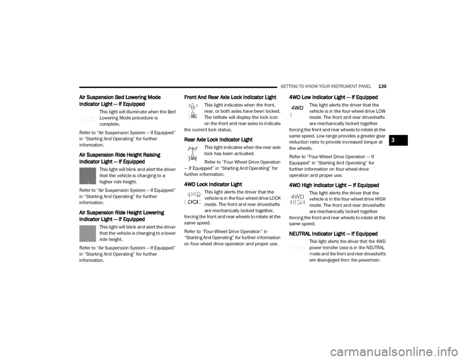
Front And Rear Axle Lock Indicator Light
This light indicates when the front,
rear, or both axles have been locked.
The telltale will display the lock icon
on the front and rear axles to indicate
the current lock status.
Rear Axle Lock Indicator Light
This light indicates when the rear axle
lock has been activated.
Refer to “Four Wheel Drive Operation
— If Equipped” in “Starting And Operating” for
further information.
4WD Lock Indicator Light
This light alerts the driver that the
vehicle is in the four-wheel drive LOCK
mode. The front and rear driveshafts
are mechanically locked together,
forcing the front and rear wheels to rotate at the
same speed.
Refer to “Four-Wheel Drive Operation” in
“Starting And Operating” for further information
on four-wheel drive operation and proper use.
4WD Low Indicator Light — If Equipped
This light alerts the driver that the
vehicle is in the four-wheel drive LOW
mode. The front and rear driveshafts
are mechanically locked together
forcing the front and rear wheels to rotate at the
same speed. Low range provides a greater gear
reduction ratio to provide increased torque at
the wheels.
Refer to “Four-Wheel Drive Operation — If
Equipped” in “Starting And Operating” for
further information on four-wheel drive
operation and proper use.
4WD High Indicator Light — If Equipped
This light alerts the driver that the
vehicle is in the four-wheel drive HIGH
mode. The front and rear driveshafts
are mechanically locked together
forcing the front and rear wheels to rotate at the
same speed.
NEUTRAL Indicator Light — If Equipped
This light alerts the driver that the 4WD
power transfer case is in the NEUTRAL
mode and the front and rear driveshafts
are disengaged from the powertrain.
3
20_DJD2_OM_EN_USC_t.book Page 139
Page 142 of 568

140GETTING TO KNOW YOUR INSTRUMENT PANEL
Low Diesel Exhaust Fluid (DEF) Indicator
Light — If Equipped
The Low Diesel Exhaust Fluid (DEF)
Indicator will illuminate if the vehicle
is low on Diesel Exhaust Fluid (DEF).
Refer to “Starting And Operating” for
further information.
Wait To Start Light — If Equipped
This indicator light will illuminate for
approximately two seconds when the
ignition is turned to the RUN position.
Its duration may be longer based on
colder operating conditions. Vehicle will not
initiate start until telltale is no longer displayed.
Refer to “Starting The Engine” in “Starting And
Operating” for further information.
NOTE:
The “Wait To Start” telltale may not illuminate if
the intake manifold temperature is warm
enough.
Water In Fuel Indicator Light — If Equipped
The “Water In Fuel Indicator Light” will
illuminate when there is water
detected in the fuel filter. If this light
remains on, DO NOT start the vehicle before you drain the water from the fuel filter to
prevent engine damage.
Refer to the “Draining Fuel/Water Separator
Filter” section in “Dealer Service” in “Servicing
And Maintenance” for further information.
GREEN INDICATOR LIGHTS
Adaptive Cruise Control (ACC) Set With
Target Light — If Equipped
This will display when the ACC is set
and a target vehicle is detected.
Refer to “Adaptive Cruise Control
(ACC) — If Equipped” in “Starting And Operating”
for further information.
Adaptive Cruise Control (ACC) Set With No
Target Detected Indicator Light — If
Equipped
This light will turn on when the
Adaptive Cruise Control is SET and
there is no target vehicle detected.
Refer to "Adaptive Cruise Control (ACC) — If
Equipped" in "Starting And Operating" for
further information.
Automatic Diesel Exhaust Brake Indicator
Light — If Equipped
This indicator light will illuminate
when the Diesel Exhaust Brake has
been activated, and has switched to
Automatic mode.
Refer to “Diesel Exhaust Brake — Engine
Braking (If Equippes)” in “Starting And
Operating” for further information.
ECO Mode Indicator Light
This light will turn on when ECO Mode
is active.
Park/Headlight On Indicator Light
This indicator light will illuminate
when the park lights or headlights are
turned on.
Refer to “Exterior Lights” in “Getting To Know
Your Vehicle” for further information.
LaneSense Indicator Light — If Equipped
The LaneSense indicator light
illuminates solid green when both
lane markings have been detected
and the system is “armed” and ready
20_DJD2_OM_EN_USC_t.book Page 140
Page 150 of 568
148SAFETY
Full Off — If Equipped
This mode is intended for off-highway or
off-road use only and should not be used on any
public roadways. In this mode, TCS and ESC
features are turned off. To enter the “Full Off”
mode, push and hold the “ESC OFF” switch for
five seconds while the vehicle is stopped with
the engine running. After five seconds, a chime
will sound, the “ESC OFF Indicator Light” will
illuminate, and the “ESC OFF” message will
display in the instrument cluster. To turn ESC on
again, momentarily push the “ESC OFF” switch.
NOTE:
System may switch from ESC “Full Off” to
“Partial Off” mode when vehicle exceeds a
predetermined speed. When the vehicle speed
slows below the predetermined speed the
system will return to ESC “Full Off”.
ESC modes may also be affected by drive
modes (if equipped).ESC Activation/Malfunction Indicator Light
And ESC OFF Indicator Light
The “ESC Activation/Malfunction
Indicator Light” in the instrument
cluster will come on when the ignition
is turned to the ON mode. It should go
out with the engine running. If the “ESC
Activation/Malfunction Indicator Light” comes
on continuously with the engine running, a
malfunction has been detected in the ESC
system. If this light remains on after several
ignition cycles, and the vehicle has been driven
several miles (kilometers) at speeds greater
than 30 mph (48 km/h), see an authorized
dealer as soon as possible to have the problem
diagnosed and corrected.
The “ESC Activation/Malfunction Indicator
Light” (located in the instrument cluster) starts
to flash as soon as the tires lose traction and
the ESC system becomes active. The “ESC
Activation/Malfunction Indicator Light” also
flashes when TCS is active. If the “ESC
Activation/Malfunction Indicator Light” begins
WARNING!
In the ESC “Full Off” mode, the engine
torque reduction and stability features are
disabled. Therefore, enhanced vehicle
stability offered by the ESC system is
unavailable. In an emergency evasive
maneuver, the ESC system will not engage
to assist in maintaining stability. ESC “Full
Off” mode is intended for off-highway or
off-road use only.
The Electronic Stability Control (ESC)
cannot prevent the natural laws of physics
from acting on the vehicle, nor can it
increase the traction afforded by prevailing
road conditions. ESC cannot prevent all
accidents, including those resulting from
excessive speed in turns, driving on very
slippery surfaces, or hydroplaning. ESC also
cannot prevent collisions.
20_DJD2_OM_EN_USC_t.book Page 148
Page 154 of 568
152SAFETY
Disabling And Enabling HSA
This feature can be turned on or turned off. To
change the current setting, proceed as follows:
If disabling HSA using your instrument cluster
display, refer to “Instrument Cluster Display”
in “Getting To Know Your Instrument Panel”
for further information.
If disabling HSA using Uconnect Settings,
refer to “Uconnect Settings” in “Multimedia”
for further information.
For vehicles not equipped with an instrument
cluster display, perform the following steps:
1. Center the steering wheel (front wheels pointing straight forward).
2. Shift the transmission into PARK.
3. Apply the parking brake.
4. Start the engine.
5. Rotate the steering wheel slightly more than one-half turn to the left.
6. Push the “ESC OFF” button located in the lower switch bank below the climate control
four times within 20 seconds. The “ESC OFF
Indicator Light” should turn on and turn off
two times.
7. Rotate the steering wheel back to center and then an additional slightly more than
one-half turn to the right.
8. Place the ignition in the OFF mode and then back to ON. If the sequence was completed
properly, the “ESC OFF Indicator Light” will blink several times to confirm HSA is
disabled.
9. Repeat these steps if you want to return this feature to its previous setting.
Towing With HSA
HSA will also provide assistance to mitigate roll
back while towing a trailer.
WARNING!
There may be situations where the Hill Start
Assist (HSA) will not activate and slight rolling
may occur, such as on minor hills or with a
loaded vehicle, or while pulling a trailer. HSA
is not a substitute for active driving
involvement. It is always the driver’s
responsibility to be attentive to distance to
other vehicles, people, and objects, and most
importantly brake operation to ensure safe
operation of the vehicle under all road
conditions. Your complete attention is always
required while driving to maintain safe control
of your vehicle. Failure to follow these
warnings can result in a collision or serious
personal injury.
WARNING!
If you use a trailer brake controller with your
trailer, the trailer brakes may be activated
and deactivated with the brake switch. If so,
there may not be enough brake pressure to
hold both the vehicle and the trailer on a hill
when the brake pedal is released. In order to
avoid rolling down an incline while resuming
acceleration, manually activate the trailer
brake or apply more vehicle brake pressure
prior to releasing the brake pedal.
HSA is not a parking brake. Always apply
the parking brake fully when exiting your
vehicle. Also, be certain to place the trans -
mission in PARK.
Failure to follow these warnings can result
in a collision or serious personal injury.
20_DJD2_OM_EN_USC_t.book Page 152
Page 160 of 568
158SAFETY
NOTE:
When a trailer with an electric brake is
connected to the vehicle, the instrument cluster
display will provide a menu to allow a selection
of the trailer type. There will be two options
provided: Conventional and Goose/Fifth Wheel.
Goose/Fifth Wheel Trailer is incompatible and
when selected, the BSM system will disable
until the trailer is disconnected. If the wrong
option is selected, the system can be reset by
either disconnecting and reconnecting the
trailer harness connector or disabling then
re-enabling the Blind Spot Monitoring System in
the customer settings in the Uconnect. This will
prompt the trailer selection menu again to allow
for the correct selection.
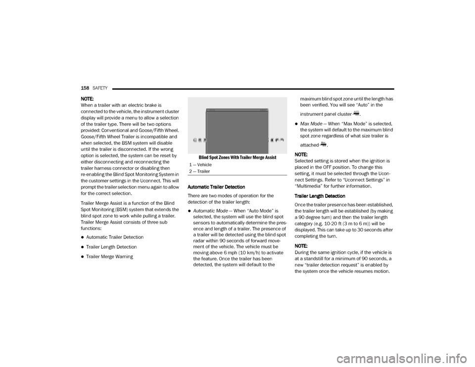
Trailer Merge Assist is a function of the Blind
Spot Monitoring (BSM) system that extends the
blind spot zone to work while pulling a trailer.
Trailer Merge Assist consists of three sub
functions:
Automatic Trailer Detection
Trailer Length Detection
Trailer Merge Warning
Blind Spot Zones With Trailer Merge Assist
Automatic Trailer Detection
There are two modes of operation for the
detection of the trailer length:
Automatic Mode — When “Auto Mode” is
selected, the system will use the blind spot
sensors to automatically determine the pres -
ence and length of a trailer. The presence of
a trailer will be detected using the blind spot
radar within 90 seconds of forward move -
ment of the vehicle. The vehicle must be
moving above 6 mph (10 km/h) to activate the feature. Once the trailer has been
detected, the system will default to the maximum blind spot zone until the length has
been verified. You will see “Auto” in the
instrument panel cluster .
Max Mode
— When “Max Mode” is selected,
the system will default to the maximum blind
spot zone regardless of what size trailer is
attached .
NOTE:
Selected setting is stored when the ignition is
placed in the OFF position. To change this
setting, it must be selected through the Ucon -
nect Settings. Refer to “Uconnect Settings” in
“Multimedia” for further information.
Trailer Length Detection
Once the trailer presence has been established,
the trailer length will be established (by making
a 90 degree turn) and then the trailer length
category (e.g. 10-20 ft (3 m to 6 m)) will be
displayed. This can take up to 30 seconds after
completing the turn.
NOTE:
During the same ignition cycle, if the vehicle is
at a standstill for a minimum of 90 seconds, a
new “trailer detection request” is enabled by
the system once the vehicle resumes motion.
1 — Vehicle
2 — Trailer
20_DJD2_OM_EN_USC_t.book Page 158
Page 162 of 568

160SAFETY
General Information
The following regulatory statement applies to all
Radio Frequency (RF) devices equipped in this
vehicle:
This device complies with Part 15 of the FCC
Rules and with Innovation, Science and
Economic Development Canada license-exempt
RSS standard(s). Operation is subject to the
following two conditions:
1. This device may not cause harmful
interference, and
2. This device must accept any interference received, including interference that may
cause undesired operation. Le présent appareil est conforme aux CNR
d`Innovation, Science and Economic
Development applicables aux appareils radio
exempts de licence. L'exploitation est autorisée
aux deux conditions suivantes:
1. l'appareil ne doit pas produire de
brouillage, et
2. l'utilisateur de l'appareil doit accepter tout brouillage radioélectrique subi, même si le
brouillage est susceptible d'en compro -
mettre le fonctionnement.
La operación de este equipo está sujeta a las
siguientes dos condiciones:
1. es posible que este equipo o dispositivo no cause interferencia perjudicial y
2. este equipo o dispositivo debe aceptar cualquier interferencia, incluyendo la que
pueda causar su operación no deseada.
NOTE:
Changes or modifications not expressly
approved by the party responsible for compli -
ance could void the user’s authority to operate
the equipment.
FORWARD COLLISION WARNING (FCW)
W
ITH MITIGATION — IF EQUIPPED
The Forward Collision Warning (FCW) system
provides the driver with audible, visual warnings
(within the instrument cluster display), and may
apply a haptic warning in the form of a brake
jerk, to warn the driver when it detects a
potential frontal collision. The warnings are
intended to provide the driver with enough time
to react, avoid or mitigate the potential collision.
NOTE:
FCW monitors the information from the forward
looking sensors as well as Electronic Brake
Controller (EBC), to calculate the probability of a
forward collision. When the system determines
that a forward collision is probable, the driver
will be provided with audible and visual warn-
ings as well as a possible haptic warning in the
form of a brake jerk.
If the driver does not take action based upon
these progressive warnings, then the system
will provide a limited level of active braking to
help slow the vehicle and mitigate the potential
forward collision. If the driver reacts to the warn -
ings by braking and the system determines that
the driver intends to avoid the collision by
WARNING!
The Blind Spot Monitoring system is only an
aid to help detect objects in the blind spot
zones. The BSM system is not designed to
detect pedestrians, bicyclists, or animals.
Even if your vehicle is equipped with the BSM
system, always check your vehicle’s mirrors,
glance over your shoulder, and use your turn
signal before changing lanes. Failure to do so
can result in serious injury or death.
20_DJD2_OM_EN_USC_t.book Page 160