wheel RAM CHASSIS CAB 2021 Workshop Manual
[x] Cancel search | Manufacturer: RAM, Model Year: 2021, Model line: CHASSIS CAB, Model: RAM CHASSIS CAB 2021Pages: 463, PDF Size: 21.5 MB
Page 189 of 463
STARTING AND OPERATING187
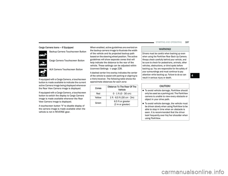
Cargo Camera Icons — If Equipped
Backup Camera Touchscreen Button
Cargo Camera Touchscreen Button
AUX Camera Touchscreen Button
If equipped with a Cargo Camera, a touchscreen
button is made available to indicate the current
active Camera image being displayed whenever
the Rear View Camera image is displayed.
If equipped with a Cargo Camera, a touchscreen
button to switch the display to Cargo Camera
image is made available whenever the Rear
View Camera image is displayed.
A touchscreen button "X" to disable display of
the camera image is made available when the
vehicle is not in REVERSE gear. When enabled, active guidelines are overlaid on
the backup camera image to illustrate the width
of the vehicle and its projected backup path
based on the steering wheel position. The active
guidelines will show separate zones that will
help indicate the distance to the rear of the
vehicle. These settings can be adjusted within
Uconnect Settings Ú
page 228.
A dashed center line overlay indicates the center
of the vehicle to assist with parking or aligning to
a hitch/receiver. The following table shows the
approximate distances for each zone:
Zones Distance To The Rear Of The
Vehicle
Red 0 - 1 ft (0 - 30 cm)
Yellow 1 ft - 6.5 ft (30 cm - 2m)
Green 6.5 ft or greater
(2 m or greater)
WARNING!
Drivers must be careful when backing up even
when using the ParkView Rear Back Up Camera.
Always check carefully behind your vehicle, and
be sure to check for pedestrians, animals, other
vehicles, obstructions, or blind spots before
backing up. You are responsible for the safety of
your surroundings and must continue to pay
attention while backing up. Failure to do so can
result in serious injury or death.
CAUTION!
To avoid vehicle damage, ParkView should
only be used as a parking aid. The ParkView
camera is unable to view every obstacle or
object in your drive path.
To avoid vehicle damage, the vehicle must
be driven slowly when using ParkView to be
able to stop in time when an obstacle is
seen. It is recommended that the driver
look frequently over his/her shoulder when
using ParkView.
4
21_DPF_OM_EN_USC_t.book Page 187
Page 191 of 463
STARTING AND OPERATING189
Zoom View is not available with the AUX
Camera feature.
The display will always default to the Trailer
Camera display (AUX 1).
SURROUND VIEW CAMERA SYSTEM — IF
EQUIPPED
Your vehicle may be equipped with the Surround
View Camera system that allows you to see an
on-screen image of the surroundings and Top
View of your vehicle whenever the gear selector is
put into REVERSE or manually activated via the
Uconnect system. The Top View of the vehicle will
show which doors are open. The image will be
displayed on the touchscreen display along with
a caution note “Check Entire Surroundings”
across the top of the screen. After five seconds,
this note will disappear. The Surround View
Camera system is comprised of three sequential
cameras located in the front grille and side
mirrors, in addition to a fourth Rear Back Up
Camera.
NOTE:
For the 3500, 4500, and 5500 Chassis Cab vehi
-
cles, the Rear Backup Camera is shipped loose
and not installed. Please refer to the Ram Body
Builder’s Guide for more information.
The Surround View Camera system has
programmable settings that may be selected
through the Uconnect system Ú page 228.
Press this button on the touchscreen
to enter the Surround View Camera
menu in the Uconnect system.
When the vehicle is shifted into REVERSE, the
Rear View and Top View is the default view of
the system.
If the camera delay is turned on, the camera
image will display for up to 10 seconds after
shifting out of REVERSE. The camera image will
not display for 10 seconds if the vehicle speed
exceeds 8 mph (13 km/h), the vehicle is shifted
into PARK, or the ignition is placed in the OFF
position. The “X” button on the touchscreen
disables the display of the camera image.
If the camera delay is turned off, the camera
image will close and display the previous screen
after shifting out of REVERSE. If active guidelines are enabled, the lines are
overlaid on the image in the Rear View to
illustrate the width of the vehicle. The view
will also include the side view mirrors and its
projected back up path based on the steering
wheel position.
There are different colored zones to indicate the
distance to the rear of the vehicle. Refer to the
chart below:
Modes Of Operation
Standard Rear View can be manually activated
by selecting “Back Up Camera” through the
Controls menu within the Uconnect system.
Top View
The Top View will show in the Uconnect system
with Rear View and Front View in a split screen
display. There are integrated ParkSense arcs in
the image at the front and rear of the vehicle.
Zone
Distance To The Rear Of The
Vehicle
Red 0 - 1 ft (0 - 30 cm)
Yellow 1 ft - 6.5 ft (30 cm - 2 m)
Green 6.5 ft or greater
(2 m or greater)
4
21_DPF_OM_EN_USC_t.book Page 189
Page 202 of 463

200STARTING AND OPERATING
GROSS AXLE WEIGHT RATING (GAWR)
The GAWR is the maximum permissible load
on the front and rear axles. The load must be
distributed in the cargo area so that the GAWR
of each axle is not exceeded.
Each axle GAWR is determined by the
components in the system with the lowest load
carrying capacity (axle, springs, tires or wheels).
Heavier axles or suspension components
sometimes specified by purchasers for increased
durability does not necessarily increase the
vehicle's GVWR.
TIRE SIZE
The tire size on the Vehicle Certification Label
represents the actual tire size on your vehicle.
Replacement tires must be equal to the load
capacity of this tire size.
RIM SIZE
This is the rim size that is appropriate for the tire
size listed.
INFLATION PRESSURE
This is the cold tire inflation pressure for your
vehicle for all loading conditions up to full GAWR.
CURB WEIGHT
The curb weight of a vehicle is defined as the
total weight of the vehicle with all fluids, including
vehicle fuel, at full capacity conditions, and with
no occupants or cargo loaded into the vehicle.
The front and rear curb weight values are
determined by weighing your vehicle on a
commercial scale before any occupants or
cargo are added.
LOADING
The actual total weight and the weight of the
front and rear of your vehicle at the ground can
best be determined by weighing it when it is
loaded and ready for operation.
The entire vehicle should first be weighed on a
commercial scale to ensure that the GVWR has
not been exceeded. The weight on the front and
rear of the vehicle should then be determined
separately to be sure that the load is properly
distributed over the front and rear axles.
Weighing the vehicle may show that the GAWR
of either the front or rear axle has been
exceeded but the total load is within the
specified GVWR. If so, weight must be shifted
from front to rear or rear to front as appropriate
until the specified weight limitations are met. Store the heavier items down low and be sure
that the weight is distributed equally. Stow all
loose items securely before driving.
Improper weight distributions can have an
adverse effect on the way your vehicle steers
and handles and the way the brakes operate.
TRAILER TOWING
In this section you will find safety tips and
information on limits to the type of towing you
can reasonably do with your vehicle. Before
towing a trailer, carefully review this information
to tow your load as efficiently and safely as
possible.
To maintain the New Vehicle Limited Warranty
coverage, follow the requirements and
recommendations in this manual concerning
vehicles used for trailer towing.
CAUTION!
Do not load your vehicle any heavier than the
GVWR or the maximum front and rear GAWR. If
you do, parts on your vehicle can break, or it
can change the way your vehicle handles.
This could cause you to lose control. Also
overloading can shorten the life of your vehicle.
21_DPF_OM_EN_USC_t.book Page 200
Page 203 of 463

STARTING AND OPERATING201
COMMON TOWING DEFINITIONS
The following trailer towing related definitions
will assist you in understanding the following
information:
Gross Vehicle Weight Rating (GVWR)
The GVWR is the total allowable weight of your
vehicle. This includes driver, passengers, cargo
and tongue weight. The total load must be
limited so that you do not exceed the GVWR
Úpage 199.
Gross Trailer Weight (GTW)
The GTW is the weight of the trailer plus
the weight of all cargo, consumables and
equipment (permanent or temporary) loaded
in or on the trailer in its "loaded and ready for
operation" condition.
The recommended way to measure GTW is to
put your fully loaded trailer on a vehicle scale.
The entire weight of the trailer must be
supported by the scale.
Gross Combination Weight Rating (GCWR)
The GCWR is the total allowable weight of your
vehicle and trailer when weighed in combination.
Gross Axle Weight Rating (GAWR)
The GAWR is the maximum capacity of the front and
rear axles. Distribute the load over the front and rear
axles evenly. Make sure that you do not exceed
either front or rear GAWR
Ú
page 199.
Tongue Weight (TW)
The TW is the downward force exerted on the
hitch ball by the trailer. You must consider this
as part of the load on your vehicle.
Trailer Frontal Area
The frontal area is the maximum height
multiplied by the maximum width of the front
of a trailer.
Trailer Sway Control (TSC)
The TSC can be a mechanical telescoping link that
can be installed between the hitch receiver and the
trailer tongue that typically provides adjustable
friction associated with the telescoping motion to
dampen any unwanted trailer swaying motions
while traveling.
If equipped, the electronic TSC recognizes a
swaying trailer and automatically applies
individual wheel brakes and/or reduces engine
power to attempt to eliminate the trailer sway.
Weight-Carrying Hitch
A weight-carrying hitch supports the trailer tongue
weight, just as if it were luggage located at a hitch
ball or some other connecting point of the vehicle.
These kinds of hitches are commonly used to tow
small and medium sized trailers.
WARNING!
If the gross trailer weight is 5,000 lbs
(2,267 kg) or more, it is recommended to use
a weight-distributing hitch to ensure stable
handling of your vehicle. If you use a standard
weight-carrying hitch, you could lose control
of your vehicle and cause a collision.
WARNING!
It is important that you do not exceed the
maximum front or rear GAWR. A dangerous
driving condition can result if either rating
is exceeded. You could lose control of the
vehicle and have a collision.
4
21_DPF_OM_EN_USC_t.book Page 201
Page 205 of 463
STARTING AND OPERATING203
Recommended Distribution Hitch Adjustment
1. Position the truck to be ready to connect to
the trailer (do not connect the trailer).
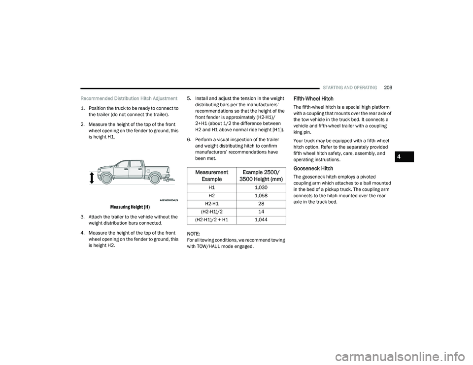
2. Measure the height of the top of the front wheel opening on the fender to ground, this
is height H1.
Measuring Height (H)
3. Attach the trailer to the vehicle without the weight distribution bars connected.
4. Measure the height of the top of the front wheel opening on the fender to ground, this
is height H2. 5. Install and adjust the tension in the weight
distributing bars per the manufacturers’
recommendations so that the height of the
front fender is approximately (H2-H1)/
2+H1 (about 1/2 the difference between
H2 and H1 above normal ride height [H1]).
6. Perform a visual inspection of the trailer and weight distributing hitch to confirm
manufacturers’ recommendations have
been met.
NOTE:
For all towing conditions, we recommend towing
with TOW/HAUL mode engaged.Fifth-Wheel Hitch
The fifth-wheel hitch is a special high platform
with a coupling that mounts over the rear axle of
the tow vehicle in the truck bed. It connects a
vehicle and fifth-wheel trailer with a coupling
king pin.
Your truck may be equipped with a fifth wheel
hitch option. Refer to the separately provided
fifth wheel hitch safety, care, assembly, and
operating instructions.
Gooseneck Hitch
The gooseneck hitch employs a pivoted
coupling arm which attaches to a ball mounted
in the bed of a pickup truck. The coupling arm
connects to the hitch mounted over the rear
axle in the truck bed.Measurement Example Example 2500/
3500 Height (mm)
H1 1,030
H2 1,058
H2-H1 28
(H2-H1)/2 14
(H2-H1)/2 + H1 1,044
4
21_DPF_OM_EN_USC_t.book Page 203
Page 206 of 463

204STARTING AND OPERATING
TRAILER HITCH TYPE AND MAXIMUM TRAILER WEIGHT
The following chart provides the industry standard for the maximum trailer weight a given trailer hitch class can tow and should be used to assist you
in selecting the correct trailer hitch for your intended towing condition.
Trailer Hitch Classification Definitions
Class Max. Trailer Hitch Industry Standards
Class I - Light Duty 2,000 lbs (907 kg)
Class II - Medium Duty 3,500 lbs (1,587 kg)
Class III - Heavy Duty 6,000 lbs (2,722 kg)
Class IV - Extra Heavy Duty 10,000 lbs (4,535 kg)
Fifth Wheel/Gooseneck Greater than 10,000 lbs (4,535 kg)
Refer to the “Trailer Towing Weights (Maximum Trailer Weight Ratings)” for the Maximum Gross Trailer Weight (GTW) towable for your given drivetrain.
All trailer hitches should be professionally installed on your vehicle.
21_DPF_OM_EN_USC_t.book Page 204
Page 207 of 463

STARTING AND OPERATING205
TRAILER TOWING WEIGHTS (MAXIMUM
T
RAILER WEIGHT RATINGS)
NOTE:
For trailer towing information (maximum trailer
weight ratings) refer to the following website
addresses:
ramtrucks.com/en/towing_guide/
ramtruck.ca (Canada)
rambodybuilder.com
TRAILER AND TONGUE WEIGHT
Never exceed the maximum tongue weight
stamped on your bumper or trailer hitch.
Weight Distribution
Consider the following items when computing
the weight on the rear axle of the vehicle:The tongue weight of the trailer.
The weight of any other type of cargo or
equipment put in or on your vehicle.
The weight of the driver and all passengers.
NOTE:
Remember that everything put into or on the
trailer adds to the load on your vehicle. Also, addi -
tional factory-installed options or dealer-installed
options must be considered as part of the total
load on your vehicle. For the maximum combined
weight of occupants and cargo for your vehicle
Ú
page 411.
TOWING REQUIREMENTS
To promote proper break-in of your new vehicle
drivetrain components, the following guidelines
are recommended.
Perform the maintenance listed in the
“Scheduled Servicing” Ú page 353. When
towing a trailer, never exceed the GAWR or
GCWR ratings.
CAUTION!
Always load a trailer with 60% of the weight in
the front of the trailer. This places 10% of the
GTW on the tow hitch of your vehicle. Loads
balanced over the wheels or heavier in the
rear can cause the trailer to sway severely
side to side which will cause loss of control of
the vehicle and trailer. Failure to load trailers
heavier in front is the cause of many trailer
collisions.
CAUTION!
Do not tow a trailer at all during the first
500 miles (805 km) the new vehicle is driven. The engine, axle or other parts could
be damaged.
Then, during the first 500 miles (805 km)
that a trailer is towed, do not drive over
50 mph (80 km/h) and do not make starts
at full throttle. This helps the engine and
other parts of the vehicle wear in at the
heavier loads.
4
21_DPF_OM_EN_USC_t.book Page 205
Page 208 of 463
206STARTING AND OPERATING
(Continued)
Towing Requirements — Tires
Do not attempt to tow a trailer while using a
compact spare tire.
Do not drive more than 50 mph (80 km/h) when towing while using a full size spare tire.
Proper tire inflation pressures are essential
to the safe and satisfactory operation of your
vehicle.
Check the trailer tires for proper tire inflation
pressures before trailer usage.
Check for signs of tire wear or visible tire
damage before towing a trailer.
For the proper tire replacement procedures.
Replacing tires with a higher load carrying
capacity will not increase the vehicle's GVWR
and GAWR limits.
For further information Ú page 406.
Towing Requirements — Trailer Brakes
Do not interconnect the hydraulic brake
system or vacuum system of your vehicle
with that of the trailer. This could cause inad -
equate braking and possible personal injury.
An electronically actuated trailer brake
controller is required when towing a trailer
with electronically actuated brakes. When
towing a trailer equipped with a hydraulic
surge actuated brake system, an electronic
brake controller is not required.
Trailer brakes are recommended for trailers
over 1,000 lbs (453 kg) and required for
trailers in excess of 2,000 lbs (907 kg).
WARNING!
Make certain that the load is secured in the
trailer and will not shift during travel. When
trailering cargo that is not fully secured,
dynamic load shifts can occur that may be diffi -
cult for the driver to control. You could lose
control of your vehicle and have a collision.
When hauling cargo or towing a trailer, do
not overload your vehicle or trailer. Over -
loading can cause a loss of control, poor
performance or damage to brakes, axle,
engine, transmission, steering, suspension,
chassis structure or tires.
Safety chains must always be used
between your vehicle and trailer. Always
connect the chains to the hook retainers of
the vehicle hitch. Cross the chains under
the trailer tongue and allow enough slack
for turning corners.
Vehicles with trailers should not be parked
on a grade. When parking, apply the
parking brake on the tow vehicle. Put the
tow vehicle transmission in PARK. For
four-wheel drive vehicles, make sure the
transfer case is not in NEUTRAL. Always,
block or "chock" the trailer wheels.
GCWR must not be exceeded.
Total weight must be distributed between
the tow vehicle and the trailer such that the
following four ratings are not exceeded :
GVWR
GTW
GAWR
Tongue weight rating for the trailer
hitch utilized.
WARNING! (Continued)
21_DPF_OM_EN_USC_t.book Page 206
Page 210 of 463
208STARTING AND OPERATING
If a fault is detected in the trailer wiring or the
Integrated Trailer Brake Module (ITBM), the
“Trailer Brake Status Indicator Light” will flash.
GAIN Adjustment Buttons (+/-)
Pushing these buttons will adjust the brake
control power output to the trailer brakes in
0.5 increments. The GAIN setting can be
increased to a maximum of 10 or decreased
to a minimum of 0 (no trailer braking).
GAIN
The GAIN setting is used to set the trailer brake
control for the specific towing condition and
should be changed as towing conditions
change. Changes to towing conditions include
trailer load, vehicle load, road conditions and
weather.
Adjusting GAIN
NOTE:
This should only be performed in a traffic-free
environment at speeds of approximately
20–25 mph (30–40 km/h).
1. Make sure the trailer brakes are in good
working condition, functioning normally
and properly adjusted. See a trailer dealer
if necessary.
2. Hook up the trailer and make the electrical connections according to the trailer
manufacturer's instructions.
3. When a trailer with electric/EOH brakes is plugged in, the trailer connected message
should appear in the instrument cluster
display (if the connection is not recognized
by the ITBM, braking functions will not be
available), the GAIN setting will illuminate
and the correct type of trailer must be
selected from the instrument cluster display
options.
4. Push the UP or DOWN button on the steering wheel until “TRAILER TOW”
appears on the screen.
5. Push the RIGHT arrow on the steering wheel to enter “TRAILER TOW”. 6. Push the UP or DOWN buttons until the
Trailer Brake Type appears on the screen.
7. Push the RIGHT arrow and then push the UP or DOWN buttons until the proper Trailer
Brake Type appears on the screen.
8. In a traffic-free environment, tow the trailer on a dry, level surface at a speed of
20–25 mph (30–40 km/h) and squeeze
the manual brake control lever completely.
9. If the trailer wheels lockup (indicated by squealing tires), reduce the GAIN setting; if
the trailer wheels turn freely, increase the
GAIN setting.
Repeat steps 8 and 9 until the GAIN setting is at
a point just below trailer wheel lockup. If towing
a heavier trailer, trailer wheel lockup may not be
attainable even with the maximum GAIN setting
of 10.
21_DPF_OM_EN_USC_t.book Page 208
Page 215 of 463

STARTING AND OPERATING213
The loaded vehicle weight, including the
snowplow system, all aftermarket accessories,
driver, passengers, options, and cargo, must
not exceed either the Gross Vehicle Weight
Rating (GVWR) or Gross Axle Weight Rating
(GAWR). These weights are specified on the
Safety Compliance Certification Label on the
driver's side door opening.
NOTE:
Detach the snowplow when transporting
passengers.
Vehicle front end wheel alignment was
set to specifications at the factory without
consideration for the weight of the plow.
Front end toe-in should be checked and reset
if necessary at the beginning and end of the
snowplow season. This will help prevent uneven
tire wear.
The blade should be lowered whenever the
vehicle is parked.
Maintain and operate your vehicle and snowplow
equipment following the recommendations
provided by the specific snowplow manufacturer.
OVER THE ROAD OPERATION WITH
S
NOWPLOW ATTACHED
The blade restricts air flow to the radiator and
causes the engine to operate at higher than
normal temperatures. Therefore, when
transporting the plow, angle the blade completely
and position it as low as road or surface
conditions permit. Do not exceed 40 mph
(64 km/h). The operator should always maintain
a safe stopping distance and allow adequate
passing clearance.
OPERATING TIPS
Under ideal snow plowing conditions, 20 mph
(32 km/h) should be maximum operating
speed. The operator should be familiar with the
area and surface to be cleaned. Reduce speed
and use extreme caution when plowing
unfamiliar areas or under poor visibility.
GENERAL MAINTENANCE
Snowplows should be maintained in
accordance with the plow manufacturer's
instructions.
Keep all snowplow electrical connections and
battery terminals clean and free of corrosion.
When plowing snow, to avoid transmission and
drivetrain damage, the following precautions
should be observed.
Operate with transfer case in 4L when
plowing small or congested areas where
speeds are not likely to exceed 15 mph
(24 km/h). At higher speeds operate in
4WD High.
Vehicles with automatic transmissions
should use 4WD Low range when plowing
deep or heavy snow for extended periods of
time to avoid transmission overheating.
Do not shift the transmission unless the
engine has returned to idle and wheels have
stopped. Make a practice of stepping on the
brake pedal while shifting the transmission.
4
21_DPF_OM_EN_USC_t.book Page 213