turn signal Ram ProMaster 2020 User Guide
[x] Cancel search | Manufacturer: RAM, Model Year: 2020, Model line: ProMaster, Model: Ram ProMaster 2020Pages: 264, PDF Size: 10.11 MB
Page 65 of 264
SAFETY63
The TPMS is not a substitute for proper tire
maintenance, and it is the driver’s responsi -
bility to maintain correct tire pressure using
an accurate tire pressure gauge, even if
under-inflation has not reached the level to
trigger illumination of the TPMS Warning
Light.
Seasonal temperature changes will affect
tire pressure, and the TPMS will monitor the
actual tire pressure in the tire.
Base System
This is the TPMS warning indicator
located in the instrument cluster.
The TPMS uses wireless technology
with wheel rim mounted electronic
sensors to monitor tire pressure levels.
Sensors, mounted to each wheel as part of the
valve stem, transmit tire pressure readings to
the Receiver Module.
NOTE:
It is particularly important for you to check the
tire pressure in all of the tires on your vehicle
regularly and to maintain the proper pressure.
The TPMS consists of the following components:
Receiver Module
Four Tire Pressure Monitoring sensors
Tire Pressure Monitoring System Warning
Light
Tire Pressure Monitoring Low Pressure Warnings
The Tire Pressure Monitoring System Warning
Light will illuminate in the instrument cluster, an
audible chime will be activated, and the “Check
tire pressure” message will display when one or
more of the four active road tire pressures are
low. Should this occur, you should stop as soon
as possible, check the inflation pressure of
each tire on your vehicle, and inflate each tire to
the vehicle’s recommended cold placard pres
-
sure value. The system will automatically
update and the Tire Pressure Monitoring Light
will extinguish once the updated tire pressures
have been received. The vehicle may need to be
driven for up to 20 minutes above 15 mph
(24 km/h) to receive this information.
Check TPMS Warnings
The Tire Pressure Monitoring System Warning
Light will flash on and off for 75 seconds and
remain on solid when a system fault is detected,
an audible chime will be activated and the “Tire
Pressure Monitoring Unavailable” message will
display. If the ignition key is cycled, this
sequence will repeat providing the system fault
still exists. The TPMS Warning Light will turn off
when the fault condition no longer exists. A
system fault can occur with any of the following
scenarios:
Jamming due to electronic devices or driving
next to facilities emitting the same radio
frequencies as the TPM sensors
Installing some form of aftermarket window
tinting that affects radio wave signals
Snow or ice around the wheels or wheel
housings
Using tire chains on the vehicle
Using wheels/tires not equipped with TPM
sensors
4
20_VF_OM_EN_US_t.book Page 63
Page 68 of 264
66SAFETY
Seat Belt Systems
Buckle up even though you are an excellent
driver, even on short trips. Someone on the road
may be a poor driver and could cause a collision
that includes you. This can happen far away
from home or on your own street.
Research has shown that seat belts save lives,
and they can reduce the seriousness of injuries
in a collision. Some of the worst injuries happen
when people are thrown from the vehicle. Seat
belts reduce the possibility of ejection and the
risk of injury caused by striking the inside of the
vehicle. Everyone in a motor vehicle should be
belted at all times.
Enhanced Seat Belt Use Reminder System
(BeltAlert)
Driver and Passenger BeltAlert — If Equipped
BeltAlert is a feature intended to remind
the driver and outboard front seat passenger
(if equipped with outboard front passenger
seat BeltAlert) to buckle their seat belts. The
BeltAlert feature is active whenever the igni -
tion switch is in the AVV/START or MAR/RUN
position. Initial Indication
If the driver is unbuckled when the ignition
switch is first in the AVV/START or MAR/RUN
position, a chime will signal for a few seconds. If
the driver or outboard front seat passenger (if
equipped with outboard front passenger seat
BeltAlert) is unbuckled when the ignition switch
is first in the AVV/START or MAR/RUN position
the Seat Belt Reminder Light will turn on and
remain on until both outboard front seat belts
are buckled. The outboard front passenger seat
BeltAlert is not active when an outboard front
passenger seat is unoccupied.
BeltAlert Warning Sequence
The BeltAlert warning sequence is activated
when the vehicle is moving above a specified
vehicle speed range and the driver or outboard
front seat passenger is unbuckled (if equipped
with outboard front passenger seat BeltAlert)
(the outboard front passenger seat BeltAlert is
not active when the outboard front passenger
seat is unoccupied). The BeltAlert warning
sequence starts by blinking the Seat Belt
Reminder Light and sounding an intermittent
chime. Once the BeltAlert warning sequence
has completed, the Seat Belt Reminder Light will remain on until the seat belts are buckled.
The BeltAlert warning sequence may repeat
based on vehicle speed until the driver and
occupied outboard front seat passenger seat
belts are buckled. The driver should instruct all
occupants to buckle their seat belts.
Change of Status
If the driver or outboard front seat passenger (if
equipped with outboard front passenger seat
BeltAlert) unbuckles their seat belt while the
vehicle is traveling, the BeltAlert warning
sequence will begin until the seat belts are
buckled again.
The outboard front passenger seat BeltAlert is
not active when the outboard front passenger
seat is unoccupied. BeltAlert may be triggered
when an animal or other items are placed on
the outboard front passenger seat or when the
seat is folded flat (if equipped). It is recom
-
mended that pets be restrained in the rear seat
(if equipped) in pet harnesses or pet carriers
that are secured by seat belts, and cargo is
properly stowed.
BeltAlert can be activated or deactivated by an
authorized dealer. FCA US LLC does not recom -
mend deactivating BeltAlert.
20_VF_OM_EN_US_t.book Page 66
Page 93 of 264
SAFETY91
(Continued)
Periodic Safety Checks You Should Make
Outside The Vehicle
Tires
Examine tires for excessive tread wear and
uneven wear patterns. Check for stones, nails,
glass, or other objects lodged in the tread or
sidewall. Inspect the tread for cuts and cracks.
Inspect sidewalls for cuts, cracks, and bulges.
Check the wheel bolts for tightness. Check the
tires (including spare) for proper cold inflation
pressure.
Lights
Have someone observe the operation of brake
lights and exterior lights while you work the
controls. Check turn signal and high beam indi -
cator lights on the instrument panel.
Door Latches
Check for proper closing, latching, and locking.
Fluid Leaks
Check area under the vehicle after overnight
parking for fuel, coolant, oil, or other fluid leaks.
Also, if gasoline fumes are detected or if fuel, or
brake fluid leaks are suspected, the cause
should be located and corrected immediately.
ONLY install floor mats designed to fit your
vehicle. NEVER install a floor mat that
cannot be properly attached and secured to
your vehicle. If a floor mat needs to be
replaced, only use a FCA approved floor
mat for the specific make, model, and year
of your vehicle.
ONLY use the driver’s side floor mat on the
driver’s side floor area. To check for inter -
ference, with the vehicle properly parked
with the engine off, fully depress the accel -
erator, the brake, and the clutch pedal (if
present) to check for interference. If your
floor mat interferes with the operation of
any pedal, or is not secure to the floor,
remove the floor mat from the vehicle and
place the floor mat in your trunk.
ONLY use the passenger’s side floor mat on
the passenger’s side floor area.
WARNING!
(Continued)
ALWAYS make sure objects cannot fall or
slide into the driver’s side floor area when
the vehicle is moving. Objects can become
trapped under accelerator, brake, or clutch
pedals and could cause a loss of vehicle
control.
NEVER place any objects under the floor
mat (e.g., towels, keys, etc.). These objects
could change the position of the floor mat
and may cause interference with the accel -
erator, brake, or clutch pedals.
If the vehicle carpet has been removed and
re-installed, always properly attach carpet
to the floor and check the floor mat
fasteners are secure to the vehicle carpet.
Fully depress each pedal to check for inter -
ference with the accelerator, brake, or
clutch pedals then re-install the floor mats.
It is recommended to only use mild soap
and water to clean your floor mats. After
cleaning, always check your floor mat has
been properly installed and is secured to
your vehicle using the floor mat fasteners
by lightly pulling mat.
WARNING!
(Continued)
4
20_VF_OM_EN_US_t.book Page 91
Page 110 of 264
108STARTING AND OPERATING
While audible signals are emitted, the audio
system is not muted.
The audible signal is turned off immediately if
the distance increases. The tone cycle remains
constant if the distance measured by the inner
sensors is constant. If this condition occurs for
the external sensors, the signal is turned off
after three seconds (stopping warnings during
maneuvers parallel to walls).
ParkSense Rear Park Assist Failure
Indications
A malfunction of the ParkSense Rear Park
Assist sensors or system is indicated, during
REVERSE gear engagement, by the instrument
panel warning icon.
The warning icon is illuminated and a
message is displayed in the instru -
ment cluster display (if equipped).
Refer to “Warning Lights And
Messages” in “Getting To Know Your Instru -
ment Panel” for further information.
The sensors and wiring are tested continuously
when the ignition is in the MAR (ACC/ON/RUN)
position. Failures are indicated immediately if
they occur when the system is on. Even if the system is able to identify that a
specific sensor is in failure condition, the instru
-
ment cluster display shall indicate that the Park-
Sense Rear Park Assist system is unavailable,
without reference to the sensor in failure condi -
tion. If even a single sensor fails, the entire
system must be disabled. The system is turned
off automatically.
Cleaning The ParkSense System
Clean the Rear Park Assist sensors with water,
car wash soap and a soft cloth. Do not use
rough or hard cloths. In washing stations, clean
sensors quickly keeping the vapor jet/high pres -
sure washing nozzles at least 4 inches (10 cm)
from the sensors. Do not scratch or poke the
sensors. Otherwise, you could damage the
sensors.
ParkSense Rear Park Assist System Usage
Precautions
NOTE:
Ensure that the outer surface and the under -
side of the rear bumper is clean and clear of
snow, ice, mud, dirt or other obstruction to
keep the Rear Park Assist system operating
properly.
Jackhammers, large trucks, and other vibra -
tions could affect the performance of Rear
Park Assist.
Clean the Rear Park Assist sensors regularly,
taking care not to scratch or damage them.
The sensors must not be covered with ice,
snow, slush, mud, dirt or debris. Failure to do
so can result in the system not working prop -
erly. The Rear Park Assist system might not
detect an obstacle behind the fascia/
bumper, or it could provide a false indication
that an obstacle is behind the fascia/
bumper.
Objects such as bicycle carriers, etc., must
not be placed within 12 inches (30 cm) from
the rear fascia/bumper while driving the
vehicle. Failure to do so can result in the
system misinterpreting a close object as a
sensor problem, causing a failure indication
to be displayed in the instrument cluster
display.
20_VF_OM_EN_US_t.book Page 108
Page 120 of 264
118STARTING AND OPERATING
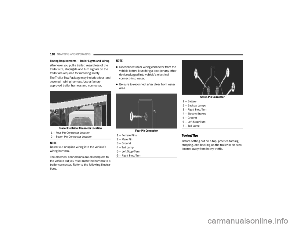
Towing Requirements — Trailer Lights And Wiring
Whenever you pull a trailer, regardless of the
trailer size, stoplights and turn signals on the
trailer are required for motoring safety.
The Trailer Tow Package may include a four- and
seven-pin wiring harness. Use a factory
approved trailer harness and connector.
Trailer Electrical Connector Location
NOTE:
Do not cut or splice wiring into the vehicle’s
wiring harness.
The electrical connections are all complete to
the vehicle but you must mate the harness to a
trailer connector. Refer to the following illustra -
tions. NOTE:Disconnect trailer wiring connector from the
vehicle before launching a boat (or any other
device plugged into vehicle’s electrical
connect) into water.
Be sure to reconnect after clear from water
area.
Four-Pin Connector Seven-Pin Connector
Towing Tips
Before setting out on a trip, practice turning,
stopping, and backing up the trailer in an area
located away from heavy traffic.
1 — Four-Pin Connector Location
2 — Seven-Pin Connector Location1 — Female Pins
2 — Male Pin
3 — Ground
4 — Tail Lamp
5 — Left Stop/Turn
6 — Right Stop/Turn
1 — Battery
2 — Backup Lamps
3 — Right Stop/Turn
4 — Electric Brakes
5 — Ground
6 — Left Stop/Turn
7 — Tail Lamp
20_VF_OM_EN_US_t.book Page 118
Page 125 of 264
123
IN CASE OF EMERGENCY
HAZARD WARNING FLASHERS
The Hazard Warning flashers switch is located
on the instrument panel below the climate
controls.Push the switch to turn on the Hazard
Warning flashers. When the switch is
activated, all directional turn signals will flash on and off to warn oncoming traffic of
an emergency. Push the switch a second time to
turn off the Hazard Warning flashers.
This is an emergency warning system and it
should not be used when the vehicle is in
motion. Use it when your vehicle is disabled and
it is creating a safety hazard for other motorists.
When you must leave the vehicle to seek assis
-
tance, the Hazard Warning flashers will
continue to operate even though the ignition is
placed in the OFF position.
NOTE:
With extended use, the Hazard Warning
flashers may wear down your battery.
BULB REPLACEMENT
Replacement Bulbs
Interior Bulbs
Bulb Name Bulb Number
Dome Lamp C5W
Courtesy Lamp FF500
Cargo Lamp C5W
Exterior Bulbs
Bulb Name Bulb Number
Front Low and High Beam Headlamp H7SLL
Front Park/Turn Signal Lamps 7444NA
6
20_VF_OM_EN_US_t.book Page 123
Page 126 of 264
124IN CASE OF EMERGENCY
Daytime Running Lamps (If Equipped) 7440
Front Side Marker Lamps W3W
Rear Tail/Stop Lamps 7443
Rear Turn Signal Lamps 7440NA
Rear Backup Lamps 921
Rear Side Marker Lamps W3W
Front Fog Lamps H11
License Plate Lamps C5W
Front Roof Lamps WY5W
Rear Roof Lamps W3W
NOTE:
Numbers refer to commercial bulb types that can be purchased from an authorized dealer. If a bulb needs to be replaced, visit an authorized dealer.
Exterior Bulbs
Bulb Name Bulb Number
20_VF_OM_EN_US_t.book Page 124
Page 127 of 264
IN CASE OF EMERGENCY125
Replacing Exterior Bulbs
Headlamps Low Beam And High beam
1. Remove one retaining screw on the lower
headlamp filler panel. Remove filler panel.
2. Remove two retaining screws on the upper headlamp filler panel. Remove filler panel.
3. Remove one upper retaining screw from the headlamp housing.
4. Remove two lower retaining screws from the headlamp housing.
5. Pull Headlamp forward, disconnect harness electrical connector and remove the head -
lamp assembly from vehicle.
6. Remove appropriate plastic cap from the back of the headlamp housing.
7. Push down on the upper portion of the socket.
8. Pull the socket outward from reflector.
9. Pull bulb outward from socket.
10. Install new bulb. 11. Push socket back into reflector until it locks
back into place.
12. Install access cap.
13. Carefully reinstall headlamp in the same position on the vehicle, so as not to affect
headlamp aiming.
14. Install one upper retaining screw on the headlamp housing.
15. Install two lower retaining screws on the headlamp housing.
16. Carefully reinstall the lower headlamp filler panel and one retaining screw.
17. Carefully reinstall the upper headlamp filler panel and two retaining screws.
Front Turn Signal/Parking Lamps
1. Remove one retaining screw on the lowerheadlamp filler panel. Remove filler panel.
2. Remove two retaining screws on the upper headlamp filler panel. Remove filler panel.
3. Remove one upper retaining screw from the headlamp housing. 4. Remove two lower retaining screws from
the headlamp housing.
5. Pull Headlamp forward, disconnect the harness electrical connector and remove
the headlamp assembly from vehicle.
6. Rotate the bulb counterclockwise and remove.
7. Install the bulb into socket, and rotate bulb/ socket clockwise into lamp locking it in
place.
8. Carefully reinstall headlamp in the same position on the vehicle, so as not to affect
headlamp aiming.
9. Install the one upper retaining screw on headlamp housing.
10. Install the two lower retaining screws on headlamp housing.
11. Carefully reinstall the lower headlamp filler panel and one retaining screw.
12. Carefully reinstall the upper headlamp filler panel and two retaining screws.
6
20_VF_OM_EN_US_t.book Page 125
Page 128 of 264
126IN CASE OF EMERGENCY
Daytime Running Lamp (DRL)/Front Side Marker
Lamp
1. Remove one retaining screw on the lower headlamp filler panel. Remove filler panel.
2. Remove two retaining screws on the upper headlamp filler panel. Remove filler panel.
3. Remove one upper retaining screw from the headlamp housing.
4. Remove two lower retaining screws from the headlamp housing.
5. Pull Headlamp forward, disconnect the harness electrical connector and remove
the headlamp assembly from vehicle.
6. Remove the Daytime Running Lamp (DRL), side marker bulb by pulling straight out.
7. Replace lamp as required and lock in place.
8. Reinstall plastic cap.
9. Carefully reinstall headlamp in the same position on the vehicle, as not to affect
headlamp aiming.
10. Install the one upper retaining screw on the headlamp housing. 11. Install the two lower retaining screws on the
headlamp housing.
12. Carefully reinstall the lower headlamp filler panel and one retaining screw.
13. Carefully reinstall the upper headlamp filler panel and two retaining screws.
Front Fog Lamps
1. Turn front wheels inboard to access cover inwheel liner.
2. Open the cover on the front of the wheel liner.
3. Remove connection and replace the bulb.
4. Connect the wire and rotate bulb/socket clockwise into lamp locking it in place.
5. Reinstall the plastic cap and close the cover on the wheel liner.
Front, Rear Roof Lamps
1. Remove two screw and remove the lampassembly.
2. Remove the socket bulb by turning counter -
clockwise. 3. Remove bulb and replace as needed.
4. Reinstall the bulb socket and rotate clock-
wise to lock in place.
5. Reinstall lamp.
Rear Tail, Stop, Backup, Turn Signal And Rear Side
Marker Lamps
1. Open rear doors.
2. Remove the seven (7) fasteners from the rear access cover and remove cover to gain
access to the Tail lamp assembly fasteners.
Rear Access Cover
20_VF_OM_EN_US_t.book Page 126
Page 129 of 264
IN CASE OF EMERGENCY127
3. Remove the two (2) 17mm tail light
assembly fasteners.
4. Disconnect the tail light harness connector and remove tail light assembly from the
vehicle.
5. Remove the tail/stop, turn signal, backup and rear side marker bulb/socket by
rotating counterclockwise.
6. Remove the bulb and replace as needed.
7. Reinstall bulb/socket and rotate clockwise to lock in place.
8. Reinstall lamp.
Replacing Interior Bulbs
Cargo Lamp
1. Using a suitable tool, remove either the lamp above the back door or the sliding
door lamp as needed and disconnect it. Rear Cargo Lamp Bulb Access
2. Using a suitable tool, pull open the metal bulb access on the back of the housing.
Cargo Lamp Bulb Location 3. Remove and install the replacement bulb.
4. Close the bulb access, connect the lamp
and install the lamp into place.
Dome Lamps
1. Using a suitable tool, insert the tip at thelocation shown and press inward to the
lamp to relieve the spring tension. This will
allow you to easily drop the dome lamp
assembly from its bracket and disconnect
the lamp.
Dome Lamp Assembly Location
1 — Spring Tension Relief Access
2 — Dome Lamp Assembly
6
20_VF_OM_EN_US_t.book Page 127