warning RAM PROMASTER 2021 Owner's Manual
[x] Cancel search | Manufacturer: RAM, Model Year: 2021, Model line: PROMASTER, Model: RAM PROMASTER 2021Pages: 288, PDF Size: 15.22 MB
Page 33 of 288

GETTING TO KNOW YOUR VEHICLE31
Mist
Use the Mist feature when weather conditions
make occasional usage of the wipers
necessary. Push the lever upward to the MIST
position and release for a single wiping cycle.
NOTE:
The mist feature does not activate the washer
pump; therefore, no washer fluid will be sprayed
on the windshield. The wash function must be
used in order to spray the windshield with
washer fluid.
For information on wiper care and replacement,
see Úpage 221.
CLIMATE CONTROLS
The Climate Control system allows you to
regulate the temperature, air flow, and direction
of air circulating throughout the vehicle. The
controls are located on the touchscreen (if
equipped) and on the instrument panel below
the radio.
MANUAL CLIMATE CONTROL
D
ESCRIPTIONS AND FUNCTIONS
Uconnect 3 With 5-inch Display With Manual Climate
Controls
The Manual Temperature Controls consist of a
series of three outer rotary dials (blower speed,
temperature and mode) and three inner push
buttons (Recirculation, A/C, Rear Window
Defroster).
A/C Button — If Equipped
Push the A/C button to engage the Air
Conditioning (A/C). The A/C indicator
illuminates when A/C is on.
NOTE:
For Manual Climate Controls, if the system is
in Mix, Floor or Defrost Mode, the A/C can be
turned off, but the A/C system shall remain
active to prevent fogging of the windows.
If fog or mist appears on the windshield or
side glass, select Defrost mode, and increase
blower speed if needed.
If your air conditioning performance seems
lower than expected, check the front of the
A/C condenser (located in front of the radi -
ator), for an accumulation of dirt or insects.
Clean with a gentle water spray from the front
of the radiator and through the condenser.
WARNING!
Sudden loss of visibility through the
windshield could lead to a collision. You might
not see other vehicles or other obstacles. To
avoid sudden icing of the windshield during
freezing weather, warm the windshield with
the defroster before and during windshield
washer use.
2
21_VF_OM_EN_USC_t.book Page 31
Page 39 of 288
GETTING TO KNOW YOUR VEHICLE37
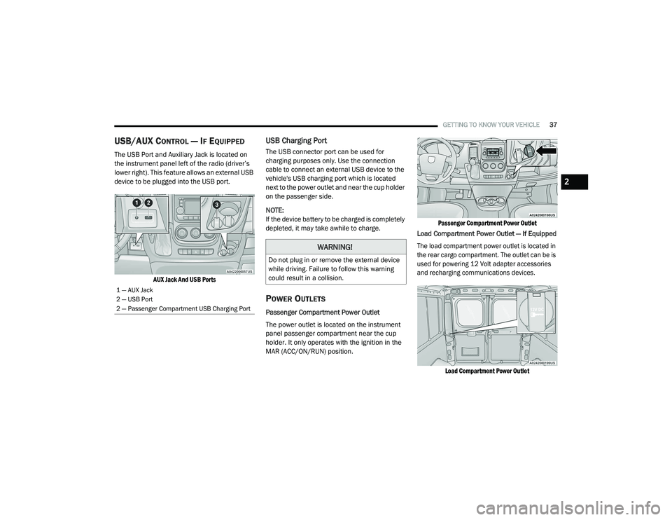
USB/AUX CONTROL — IF EQUIPPED
The USB Port and Auxiliary Jack is located on
the instrument panel left of the radio (driver’s
lower right). This feature allows an external USB
device to be plugged into the USB port.
AUX Jack And USB Ports
USB Charging Port
The USB connector port can be used for
charging purposes only. Use the connection
cable to connect an external USB device to the
vehicle's USB charging port which is located
next to the power outlet and near the cup holder
on the passenger side.
NOTE:
If the device battery to be charged is completely
depleted, it may take awhile to charge.
POWER OUTLETS
Passenger Compartment Power Outlet
The power outlet is located on the instrument
panel passenger compartment near the cup
holder. It only operates with the ignition in the
MAR (ACC/ON/RUN) position.
Passenger Compartment Power Outlet
Load Compartment Power Outlet — If Equipped
The load compartment power outlet is located in
the rear cargo compartment. The outlet can be is
used for powering 12 Volt adapter accessories
and recharging communications devices.
Load Compartment Power Outlet
1 — AUX Jack
2 — USB Port
2 — Passenger Compartment USB Charging Port
WARNING!
Do not plug in or remove the external device
while driving. Failure to follow this warning
could result in a collision.
2
21_VF_OM_EN_USC_t.book Page 37
Page 40 of 288

38GETTING TO KNOW YOUR VEHICLE
(Continued)
NOTE:
Do not connect devices with power higher than
180 W to the socket. Do not damage the socket
by using unsuitable adapters.
Power Outlet Fuses — Under Hood
AUXILIARY SWITCHES — IF EQUIPPED
Your vehicle may be equipped with two auxiliary
switches located on the instrument panel to the
left of the steering column which can be used to
power various electronic devices. Connections
to the switches are found in the right central
pillar fuse panel at the base of the passenger
side B-pillar.
Auxiliary Upfitter Switches
Auxiliary Switch 1 is configured to constant
battery feed, while Auxiliary Switch 2 is
configured to ignition feed.
For further information on using the auxiliary
switches, please refer to the Ram Body Builders
Guide by accessing www.rambodybuilder.com
and choosing the appropriate links.
1 — F14 Fuse 20 Amp Yellow Front Power Outlet
2 — F09 Fuse 15 Amp Blue Rear Power Outlet
WARNING!
To avoid serious injury or death:
Only devices designed for use in this type of
outlet should be inserted into any 12 Volt
outlet.
Do not touch with wet hands.
Close the lid when not in use and while
driving the vehicle.
If this outlet is mishandled, it may cause an
electric shock and failure.
CAUTION!
Many accessories that can be plugged in
draw power from the vehicle's battery, even
when not in use (i.e., cellular phones, etc.).
Eventually, if plugged in long enough, the
vehicle's battery will discharge sufficiently
to degrade battery life and/or prevent the
engine from starting.
Accessories that draw higher power (i.e.,
coolers, vacuum cleaners, lights, etc.) will
degrade the battery even more quickly.
Only use these intermittently and with
greater caution.
After the use of high power draw accesso -
ries, or long periods of the vehicle not being
started (with accessories still plugged in),
the vehicle must be driven a sufficient
length of time to allow the generator to
recharge the vehicle's battery.
WARNING! (Continued)
21_VF_OM_EN_USC_t.book Page 38
Page 41 of 288

GETTING TO KNOW YOUR VEHICLE39
WINDOWS
POWER WINDOWS
The control on the left front door panel has
switches that control all power windows. There
is a single opening and closing switch on the
front passenger door for passenger window
control.
Power Window Switches
NOTE:
The Key Off Power Delay feature will allow the
power windows to operate for up to three
minutes after the ignition is placed in the STOP
(OFF/LOCK) position. This feature is cancelled
when either front door is opened.
Automatic Window Features
Auto-Down Feature — If Equipped
The window switches may be equipped with an
Auto-Down feature. Push the window switch for
half a second, release, and the window will go
down automatically.
To stop the window from going all the way down
during the auto-down operation, pull up or push
down on the switch briefly. To open the window part way, lift the window
switch to the detent for less than half a second
and release it to stop the window.
WINDOW BAR GRATES — IF EQUIPPED
This vehicle may be equipped with metal grates
over the sliding door windows. This feature is a
part of the vehicle’s safety system, and is
designed to protect you and your passengers in
the event of an accident.
Window Bar Grates
WARNING!
Never leave children alone in a vehicle, or
with access to an unlocked vehicle.
Allowing children to be in a vehicle unat -
tended is dangerous for a number of
reasons. A child or others could be seriously
or fatally injured. Children should be
warned not to touch the parking brake,
brake pedal or the gear selector.
Do not leave the key fob in or near the
vehicle or in a location accessible to chil -
dren. A child could operate power windows,
other controls, or move the vehicle.
WARNING!
The metal grates over the sliding door windows
are designed to protect you in the event of an
accident. Modification or removal of the grates
could lead to serious injury or death.
2
21_VF_OM_EN_USC_t.book Page 39
Page 43 of 288
GETTING TO KNOW YOUR VEHICLE41
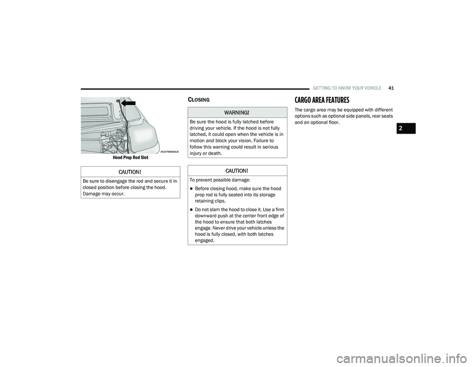
Hood Prop Rod Slot
CLOSINGCARGO AREA FEATURES
The cargo area may be equipped with different
options such as optional side panels, rear seats
and an optional floor.
CAUTION!
Be sure to disengage the rod and secure it in
closed position before closing the hood.
Damage may occur.
WARNING!
Be sure the hood is fully latched before
driving your vehicle. If the hood is not fully
latched, it could open when the vehicle is in
motion and block your vision. Failure to
follow this warning could result in serious
injury or death.
CAUTION!
To prevent possible damage:
Before closing hood, make sure the hood
prop rod is fully seated into its storage
retaining clips.
Do not slam the hood to close it. Use a firm
downward push at the center front edge of
the hood to ensure that both latches
engage. Never drive your vehicle unless the
hood is fully closed, with both latches
engaged.
2
21_VF_OM_EN_USC_t.book Page 41
Page 45 of 288

GETTING TO KNOW YOUR INSTRUMENT PANEL43
INSTRUMENT CLUSTER DESCRIPTIONS
1. Speedometer
Indicates vehicle speed.
2. Instrument Cluster Display
When the appropriate conditions exist,
this display shows instrument cluster
display messages Ú page 44.
Odometer/Trip Odometer Display Area
US Federal regulations require that upon
transfer of vehicle ownership, the seller
certify to the purchaser the correct mileage
that the vehicle has been driven. If your
odometer needs to be repaired or serviced,
the repair technician should leave the odom -
eter reading the same as it was before the
repair or service. If the technician cannot do
so, then the odometer must be set at zero,
and a sticker must be placed in the door
jamb stating what the mileage was before the
repair or service. It is a good idea for you to
make a record of the odometer reading before the repair/service, so that you can be
sure that it is properly reset, or that the door
jamb sticker is accurate if the odometer must
be reset at zero.
Gear Selector Status (PRND)
The gear selector status “P,R,N,D,1,2,3,4,5,
6” are displayed indicating the gear selector
position. Telltales “1,2,3,4,5,6” indicate the
manual mode has been engaged and the
gear selected is displayed Ú page 60.
Instrument Cluster Display Location
3. Tachometer
This gauge measures engine revolutions
per minute (RPM x 1000). Before the
pointer reaches the red area, ease up on
the accelerator to prevent engine
damage.
4. Temperature Gauge
The temperature gauge shows engine
coolant temperature. Any reading within
the normal range indicates that the engine
cooling system is operating satisfactorily.
The pointer will likely indicate a higher
temperature when driving in hot weather
or up mountain grades. It should not be
allowed to exceed the upper limits of the
normal operating range.
WARNING!
A hot engine cooling system is dangerous. You or
others could be badly burned by steam or boiling
coolant. You may want to call an authorized
dealer for service if your vehicle overheats.
3
21_VF_OM_EN_USC_t.book Page 43
Page 46 of 288

44GETTING TO KNOW YOUR INSTRUMENT PANEL
5. Fuel Gauge
The pointer shows the level of fuel in the
fuel tank when the ignition switch is in
the ON/RUN position.
The fuel pump symbol points
to the side of the vehicle where
the fuel door is located
Ú page 75.
INSTRUMENT CLUSTER DISPLAY
Your vehicle will be equipped with an
instrument cluster display, which offers useful
information to the driver. With the ignition in the
STOP (OFF/LOCK) mode, opening/closing of a
door will activate the display for viewing, and
display the total miles, or kilometers, in the
odometer. Your instrument cluster display is
designed to display important information
about your vehicle’s systems and features.
Using a driver interactive display located on the
instrument panel, your instrument cluster
display can show you how systems are working
and give you warnings when they are not. The
steering wheel mounted controls allow you to
scroll through the main menus and submenus.
You can access the specific information you
want and make selections and adjustments.
LOCATION AND CONTROLS
The instrument cluster display features a driver
interactive display that is located in the
instrument cluster.
Instrument Cluster Display
This system allows the driver to select a variety
of useful information by pushing the switches
mounted on the instrument panel. Examples of
menu items are:
Speed Beep
Buzzer Volume
Seat Belt Buzzer
Exit Menu
CAUTION!
Driving with a hot engine cooling system could
damage your vehicle. If the temperature gauge
reads “H,” pull over and stop the vehicle. Idle
the vehicle with the air conditioner turned off
until the pointer drops back into the normal
range. If the pointer remains on the “H,” turn
the engine off immediately and call an
authorized dealer for service.
21_VF_OM_EN_USC_t.book Page 44
Page 50 of 288
48GETTING TO KNOW YOUR INSTRUMENT PANEL
Start Of Trip Procedure
With the ignition on, push and hold the TRIP
button for over two seconds to reset trip
information.
Exit Trip
To exit the Trip function, push the TRIP button
until all the trip menu items have been
displayed and the display returns to the main
menu.
TRIP FUNCTIONS
Both trip functions are resettable (reset — start
of new trip).
Trip A/Trip B
Trip Distance
Average Fuel Consumption
Average Speed
Travel Time (Driving Time)
NOTE:
“Trip B” functions may be excluded (see “Trip B
Data”). “Range” and “Instantaneous Fuel
Consumption” cannot be reset.
WARNING LIGHTS AND MESSAGES
The warning/indicator lights will illuminate in the
instrument panel together with a dedicated
message and/or acoustic signal when applicable.
These indications are indicative and precautionary
and as such must not be considered as exhaustive
and/or alternative to the information contained in
the Owner’s Manual, which you are advised to read
carefully in all cases. Always refer to the
information in this chapter in the event of a failure
indication. All active telltales will display first if
applicable. The system check menu may appear
different based upon equipment options and
current vehicle status. Some telltales are optional
and may not appear.
RED WARNING LIGHTS
Seat Belt Reminder Warning Light
When the ignition is first placed in the
ON/RUN or MAR/ON/RUN position, if
the driver’s seat belt is unbuckled, a
chime will sound and the light will turn
on. When driving, if the driver or front passenger
seat belt remains unbuckled, the Seat Belt
Reminder Light will flash or remain on
continuously and a chime will sound
Ú page 164.
Air Bag Warning Light
This light will turn on for four to eight
seconds as a bulb check when the
ignition is placed in the ON/RUN or
MAR/ON/RUN position. If the light is
either not on during startup, stays on, or turns
on while driving, have the system inspected at
an authorized dealer as soon as possible. This
light will illuminate with a single chime when a
fault with the Air Bag Warning Light has been
detected, it will stay on until the fault is cleared.
If the light comes on intermittently or remains
on while driving, have an authorized dealer
service the vehicle immediately.
Battery Charge Warning Light
This warning light will illuminate when
the battery is not charging properly. If
it stays on while the engine is running,
there may be a malfunction with the
charging system. Contact an authorized dealer
as soon as possible.
This indicates a possible problem with the
electrical system or a related component.
21_VF_OM_EN_USC_t.book Page 48
Page 51 of 288
GETTING TO KNOW YOUR INSTRUMENT PANEL49
Door Open Warning Light
This indicator will illuminate when one
or more door(s) are not fully closed.
NOTE:
If the vehicle is moving and a door is opened,
there will also be a single chime.
Electronic Throttle Control Warning Light
This warning light will illuminate to
inform of a problem with the
Electronic Throttle Control (ETC)
system. If a problem is detected while
the vehicle is running, the light will either stay
on or flash depending on the nature of the
problem. Cycle the ignition when the vehicle is
safely and completely stopped and the
transmission is placed in the PARK (P) position.
The light should turn off. If the light remains on
with the vehicle running, your vehicle will
usually be drivable; however, see an authorized
dealer for service as soon as possible.
If the light continues to flash when the vehicle is
running, immediate service is required and you
may experience reduced performance, an
elevated/rough idle, or engine stall and your
vehicle may require towing. The light will come on when the ignition is placed in the ON/RUN or
MAR/ON/RUN position and remain on briefly as
a bulb check. If the light does not come on
during starting, have the system checked by an
authorized dealer.
Transmission Fault Warning Light
This light will illuminate (together with
a message in the instrument cluster
display and a buzzer) to indicate a
transmission fault. Contact an
authorized dealer if the message remains after
restarting the engine.
Engine Temperature Warning Light
This light warns of an overheated
engine condition. If the engine
coolant temperature is too high, this
indicator will illuminate and a single
chime will sound.
If the light turns on while driving, safely pull over
and stop the vehicle. If the Air Conditioning (A/C)
system is on, turn it off. Also, shift the
transmission into NEUTRAL and idle the vehicle.
If the temperature reading does not return to
normal, turn the engine off immediately and call
for service
Ú
page 206.
Brake Warning Light
This warning light monitors various
brake functions, including brake fluid
level and parking brake application. If
the brake light turns on it may
indicate that the parking brake is applied, that
the brake fluid level is low, or that there is a
problem with the Anti-Lock Brake System
reservoir.
If the light remains on when the parking brake
has been disengaged, and the fluid level is at
the full mark on the master cylinder reservoir, it
indicates a possible brake hydraulic system
malfunction or that a problem with the Brake
Booster has been detected by the Anti-Lock
Brake System (ABS) / Electronic Stability
Control (ESC) system. In this case, the light will
remain on until the condition has been
corrected. If the problem is related to the brake
booster, the ABS pump will run when applying
the brake, and a brake pedal pulsation may be
felt during each stop.
The dual brake system provides a reserve
braking capacity in the event of a failure to a
portion of the hydraulic system. A leak in either
half of the dual brake system is indicated by the
3
21_VF_OM_EN_USC_t.book Page 49
Page 52 of 288
50GETTING TO KNOW YOUR INSTRUMENT PANEL
Brake Warning Light, which will turn on when
the brake fluid level in the master cylinder has
dropped below a specified level.
The light will remain on until the cause is
corrected.
NOTE:
The light may flash momentarily during sharp
cornering maneuvers, which change fluid level
conditions. The vehicle should have service
performed, and the brake fluid level checked.
If brake failure is indicated, immediate repair is
necessary.
Vehicles equipped with the Anti-Lock Brake
System (ABS) are also equipped with Electronic
Brake Force Distribution (EBD). In the event of
an EBD failure, the Brake Warning Light will turn
on along with the ABS Light. Immediate repair to
the ABS system is required. Operation of the Brake Warning Light can be
checked by turning the ignition switch from the
OFF position to the ON/RUN position. The light
should illuminate for approximately two
seconds. The light should then turn off unless
the parking brake is applied or a brake fault is
detected. If the light does not illuminate, have
the light inspected by an authorized dealer.
The light also will turn on when the parking
brake is applied with the ignition switch in the
ON/RUN position.
NOTE:
This light shows only that the parking brake is
applied. It does not show the degree of brake
application.
Oil Pressure Warning Light
This warning light will illuminate to
indicate low engine oil pressure. If the
light turns on while driving, stop the
vehicle, shut off the engine as soon as
possible, and contact an authorized dealer. A
chime will sound when this light turns on.
Do not operate the vehicle until the cause is
corrected. This light does not indicate how
much oil is in the engine. The engine oil level
must be checked under the hood.
Vehicle Security Warning Light — If
Equipped
This light will flash at a fast rate for
approximately 15 seconds when the
vehicle security system is arming, and
then will flash slowly until the vehicle
is disarmed.
YELLOW WARNING LIGHTS
Immobilizer Fail / VPS Electrical Alarm
Indicator Light
This telltale will illuminate when the
vehicle security system system has
detected an attempt to break into the
vehicle.
NOTE:
After cycling the ignition to the ON/RUN posi -
tion, the Vehicle Security Warning Light could
illuminate if a problem with the system is
detected. This condition will result in the engine
being shut off after two seconds.
WARNING!
Driving a vehicle with the red brake light on is
dangerous. Part of the brake system may
have failed. It will take longer to stop the
vehicle. You could have a collision. Have the
vehicle checked immediately.
21_VF_OM_EN_USC_t.book Page 50