engine RAM PROMASTER 2023 User Guide
[x] Cancel search | Manufacturer: RAM, Model Year: 2023, Model line: PROMASTER, Model: RAM PROMASTER 2023Pages: 296, PDF Size: 12.31 MB
Page 20 of 296

18GETTING TO KNOW YOUR VEHICLE
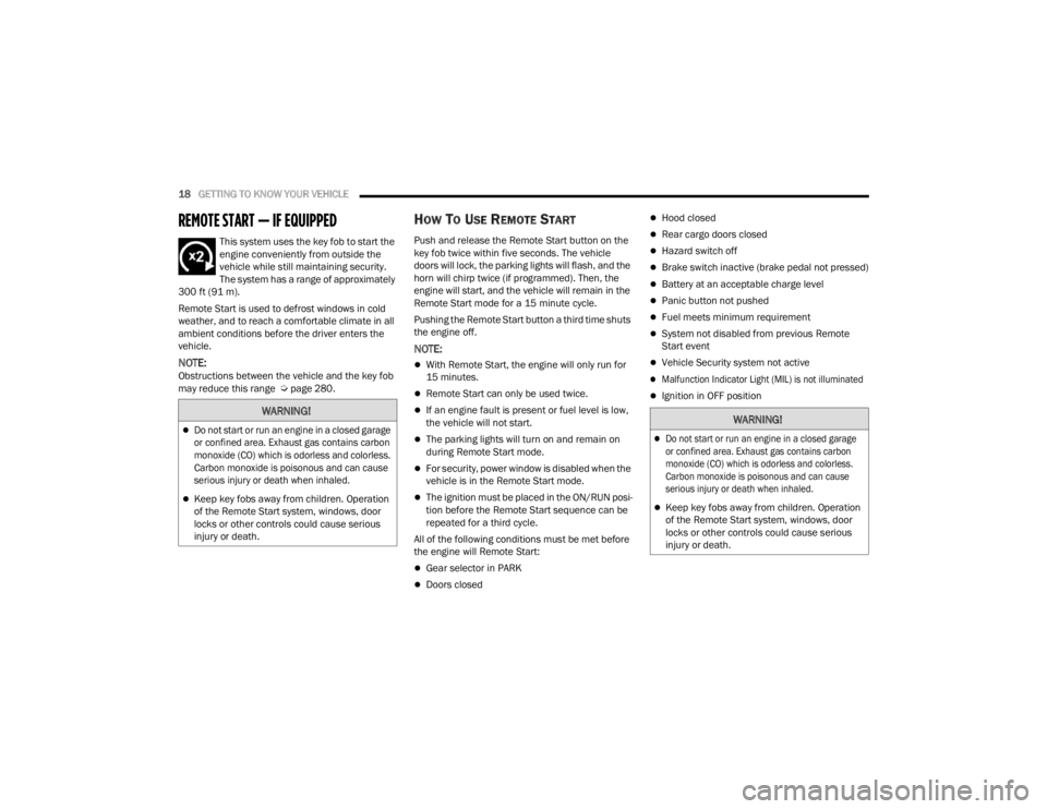
REMOTE START — IF EQUIPPED
This system uses the key fob to start the
engine conveniently from outside the
vehicle while still maintaining security.
The system has a range of approximately
300 ft (91 m).
Remote Start is used to defrost windows in cold
weather, and to reach a comfortable climate in all
ambient conditions before the driver enters the
vehicle.
NOTE:Obstructions between the vehicle and the key fob
may reduce this range Ú page 280.
HOW TO USE REMOTE START
Push and release the Remote Start button on the
key fob twice within five seconds. The vehicle
doors will lock, the parking lights will flash, and the
horn will chirp twice (if programmed). Then, the
engine will start, and the vehicle will remain in the
Remote Start mode for a 15 minute cycle.
Pushing the Remote Start button a third time shuts
the engine off.
NOTE:
With Remote Start, the engine will only run for
15 minutes.
Remote Start can only be used twice.
If an engine fault is present or fuel level is low,
the vehicle will not start.
The parking lights will turn on and remain on
during Remote Start mode.
For security, power window is disabled when the
vehicle is in the Remote Start mode.
The ignition must be placed in the ON/RUN posi -
tion before the Remote Start sequence can be
repeated for a third cycle.
All of the following conditions must be met before
the engine will Remote Start:
Gear selector in PARK
Doors closed
Hood closed
Rear cargo doors closed
Hazard switch off
Brake switch inactive (brake pedal not pressed)
Battery at an acceptable charge level
Panic button not pushed
Fuel meets minimum requirement
System not disabled from previous Remote
Start event
Vehicle Security system not active
Malfunction Indicator Light (MIL) is not illuminated
Ignition in OFF position
WARNING!
Do not start or run an engine in a closed garage
or confined area. Exhaust gas contains carbon
monoxide (CO) which is odorless and colorless.
Carbon monoxide is poisonous and can cause
serious injury or death when inhaled.
Keep key fobs away from children. Operation
of the Remote Start system, windows, door
locks or other controls could cause serious
injury or death.
23_VF_OM_EN_USC_t.book Page 18
Page 21 of 296

GETTING TO KNOW YOUR VEHICLE19
TO EXIT REMOTE START MODE
To drive the vehicle after starting the Remote Start
system, push and release the START/STOP ignition
button while pressing the brake pedal prior to the
end of the 15 minute cycle.
The Remote Start system will turn the engine off if
the Remote Start button on the key fob is pushed
again, or if the engine is allowed to run for the
entire 15 minute cycle. Once the ignition is placed
in the ON/RUN position, the climate controls
will resume the previously set operations
(temperature, blower control, etc.).
NOTE:To avoid unintentional shutdowns, the system will
disable for two seconds after receiving a valid
Remote Start request.
For vehicles equipped with the Keyless Enter ‘n Go™ —
Passive Entry feature, the message “Remote Start
Active — Push Start Button” will display in the
instrument cluster display until you push the
START/STOP ignition button.
REMOTE START DEFROST MODE
A
CTIVATION — IF EQUIPPED
When Remote Start is active, and the outside
ambient temperature is 40°F (4.5°C) or below, the
system will automatically activate rear defrost for
15 minutes or less. The timing is dependent on
the ambient temperature. Once the timer expires,
the system will automatically adjust the settings
depending on ambient conditions. See “Remote
Start Comfort Systems — If Equipped” in the next
section for detailed operation.
REMOTE START COMFORT SYSTEMS —
I
F EQUIPPED
When Remote Start is activated, the rear defrost
will automatically turn on in cold weather.
The vehicle will adjust the climate control settings
depending on the outside ambient temperature.
Manual Temperature Control (MTC) — If Equipped
In ambient temperatures of 40°F (4.5°C) or
below, the climate settings will default to
maximum heat, with fresh air entering the
cabin. If the front defrost timer expires, the
vehicle will enter Mix Mode.
In ambient temperatures from 40°F (4.5°C) to
78°F (26°C), the climate settings will be based
on the last settings selected by the driver.
In ambient temperatures of 78°F (26°C)
or above, the climate settings will default to
MAX A/C, Bi-Level mode, with Recirculation on.
For more information on ATC, MTC, and climate
control settings, see Ú page 40.
NOTE:These features will stay on through the duration of
Remote Start, or until the ignition is placed in the
ON/RUN position. The climate control settings
will change, and exit the automatic defaults, if
manually adjusted by the driver while the vehicle is
in Remote Start mode. This includes turning the
climate controls off using the OFF button.
REMOTE START WINDSHIELD WIPER
D
E-ICER ACTIVATION — IF EQUIPPED
When Remote Start is active and the outside
ambient temperature is less than 33°F (0.6°C),
the Windshield Wiper De-Icer will activate. Exiting
Remote Start will resume its previous operation.
If the Windshield Wiper De-Icer was active, the
timer and operation will continue.
2
23_VF_OM_EN_USC_t.book Page 19
Page 36 of 296

34GETTING TO KNOW YOUR VEHICLE
HIGH/LOW BEAM SWITCH
With the low beams activated, push the multifunction
lever toward the instrument panel to turn on the high
beams. The High Beam Indicator Light will illuminate in
the instrument cluster to indicated that the high beams
are on. Push the multifunction lever a second time to
switch the headlights back to low beam. When the
ignition is placed in the OFF position, both the high and
low beams will turn off.
AUTOMATIC HIGH BEAM HEADLAMP
C
ONTROL — IF EQUIPPED
The Automatic High Beam Headlamp Control
system provides increased forward lighting at night
by automating high beam control through the use
of a digital camera mounted on the windshield.
This camera detects vehicle specific light and
automatically switches from high beams to low
beams until the approaching vehicle is out of view.
NOTE:
The multifunction lever must be in the high
beam position in order for the Automatic High
Beam Headlamp Control to activate.
The Automatic High Beam Headlamp Control
can be turned on or off through Uconnect
Settings Ú page 134.
Broken, muddy, or obstructed headlights and
taillights of vehicles in the field of view will
cause headlights to remain on longer (closer to the vehicle). Also, dirt, film, and other obstruc
-
tions on the windshield or camera lens will
cause the system to function improperly.
When set to AUTO, the system automatically
turns the headlights on or off based on ambient
light levels.
FLASH-TO-PASS
You can signal another vehicle with your headlights
by lightly pulling the multifunction lever toward you.
This will cause the high beam headlights to turn on,
and remain on, until the lever is released.
AUTOMATIC HEADLIGHTS — IF EQUIPPED
To turn on the automatic headlights, turn the end
of the multifunction lever to the AUTO position. To
turn off the automatic headlights, turn the end of
the multifunction lever back to the O (off) position.
PARKING LIGHTS
These lights can be turned on, with the ignition
in the OFF position, by moving the end of the
multifunction lever to O (off) position and then to
the headlight position.
The indicator light in the instrument panel comes
on. The lights stay on until the next ignition cycle is
performed.
HEADLIGHT DELAY
When this feature is selected, the driver can
choose to have the headlights remain on for a
preset period of time after the engine is turned off.
Activation
To activate the delay feature, place the ignition in
the OFF position while the headlights are still on.
Then, rotate the multifunction lever to the O (off)
position within two minutes. The delay interval
begins when the headlight switch is turned from
O (off) to the low beam position. If the headlight
switch is in AUTO position and headlights were on
before the ignition is OFF, the delay interval begins
automatically.
Deactivation
The feature is disabled by turning on the
headlights, the parking lights or by placing the
ignition in the RUN position. If you shut off the
lights before the ignition is turned on, they will
turn off in the normal manner.
23_VF_OM_EN_USC_t.book Page 34
Page 45 of 296

GETTING TO KNOW YOUR VEHICLE43
Climate Control OFF Button
Press and release this button to turn the
Climate Control ON/OFF.
ADDITIONAL REAR CLIMATE CONTROL —
I
F EQUIPPED
These switches, mounted on the instrument panel
to the left of the steering column, activate the
additional rear heating/air conditioning system.
NOTE:These switches must be enabled for operation by
the Upfitter.
Additional Rear Climate Controls Switches
Rear Blower Control
Push this button to turn on the rear climate
controls. An indicator light will turn on when
the rear climate control is on.
OPERATING TIPS
Refer to the chart at the end of this section for
suggested control settings for various weather
conditions.
Summer Operation
The engine cooling system must be protected
with a high-quality antifreeze coolant to provide
proper corrosion protection and to protect against
engine overheating. OAT coolant (conforming to
MS.90032) is recommended.
Winter Operation
To ensure the best possible heater and defroster
performance, make sure the engine cooling
system is functioning properly and the proper
amount, type, and concentration of coolant is
used. Use of the Air Recirculation mode during
Winter months is not recommended, because it
may cause window fogging.
Vacation Storage
For information on maintaining the Climate Control
system when the vehicle is being stored for an
extended period of time, see Ú page 265.
Window Fogging
Vehicle windows tend to fog on the inside in mild, rainy,
and/or humid weather. To clear the windows, select
Defrost or Mix mode and increase the front blower
speed. Do not use the Recirculation mode without A/C
for long periods, as fogging may occur.
Outside Air Intake
Make sure the air intake, located directly in front of
the windshield, is free of obstructions, such as
leaves. Leaves collected in the air intake may
reduce airflow, and if they enter the air distribution
box, they could plug the water drains. In Winter
months, make sure the air intake is clear of ice,
slush, and snow.
Cabin Air Filter
The Climate Control system filters out dust and
pollen from the air. Contact an authorized dealer to
service your cabin air filter, and to have it replaced
when needed.
2
23_VF_OM_EN_USC_t.book Page 43
Page 48 of 296

46GETTING TO KNOW YOUR VEHICLE
(Continued)
POWER OUTLETS
Passenger Compartment Power Outlet
The power outlet is located on the instrument
panel to the right of the radio. It only operates with
the ignition in the ON/RUN position.
Passenger Compartment Power Outlet
Load Compartment Power Outlet — If Equipped
The load compartment power outlet is located in
the rear cargo compartment. The outlet can be is
used for powering 12 Volt adapter accessories and
recharging communications devices.
Load Compartment Power Outlet
NOTE:Do not connect devices with power higher than
180 W to the socket. Do not damage the socket by
using unsuitable adapters.
Power Outlet Fuses — Under Hood
1 — F14 Fuse 20 Amp Yellow Front Power Outlet
2 — F09 Fuse 15 Amp Blue Rear Power Outlet
WARNING!
To avoid serious injury or death:
Only devices designed for use in this type of outlet
should be inserted into any 12 Volt outlet.
Do not touch with wet hands.
Close the lid when not in use and while driving
the vehicle.
If this outlet is mishandled, it may cause an
electric shock and failure.
CAUTION!
Many accessories that can be plugged in draw
power from the vehicle's battery, even when not in
use (i.e., cellular phones, etc.). Eventually, if
plugged in long enough, the vehicle's battery
will discharge sufficiently to degrade battery life
and/or prevent the engine from starting.
Accessories that draw higher power (i.e., coolers,
vacuum cleaners, lights, etc.) will degrade the
battery even more quickly. Only use these intermit -
tently and with greater caution.
23_VF_OM_EN_USC_t.book Page 46
Page 55 of 296

GETTING TO KNOW YOUR INSTRUMENT PANEL53
Use this QR code to access your
digital experience.
BASE / MIDLINE INSTRUMENT CLUSTER
D
ESCRIPTIONS
1. Speedometer
Indicates vehicle speed.
2. Instrument Cluster Display
The instrument cluster display features a
driver interactive display Ú page 56.
3. Tachometer
Indicates the engine speed in revolutions
per minute (RPM x 1000).
4. Fuel Gauge
The gauge shows the level of fuel in the
fuel tank when the ignition switch is in the
ON/RUN position.
The fuel pump symbol points to
the side of the vehicle where the
fuel door is located.
5. Temperature Gauge
The temperature gauge shows engine
coolant temperature. Any reading within the
normal range indicates that the engine
cooling system is operating satisfactorily.
The gauge pointer will likely indicate a
higher temperature when driving in hot
weather or up mountain grades. It should
not be allowed to exceed the upper limits of
the normal operating range.
NOTE:The hard telltales will illuminate for a bulb check
when the ignition is first cycled.
WARNING!
A hot engine cooling system is dangerous. You or
others could be badly burned by steam or boiling
coolant. It is recommended to call an authorized
dealer for service if your vehicle overheats
Ú page 233.
CAUTION!
Driving with a hot engine cooling system could
damage your vehicle. If the temperature gauge
reads “H” pull over and stop the vehicle. Idle the
vehicle with the air conditioner turned off until
the pointer drops back into the normal range.
If the pointer remains on the “H”, turn the
engine off immediately and call an authorized
dealer for service.
3
23_VF_OM_EN_USC_t.book Page 53
Page 57 of 296

GETTING TO KNOW YOUR INSTRUMENT PANEL55
INSTRUMENT CLUSTER DESCRIPTIONS
1. Tachometer
This gauge measures engine revolutions
per minute (RPM x 1000). Before the
pointer reaches the red area, ease up on
the accelerator to prevent engine damage.
2. Instrument Cluster Display
When the appropriate conditions exist, this
display shows instrument cluster display
messages Ú page 56.
Odometer/Trip Odometer Display Area
US Federal regulations require that upon transfer of
vehicle ownership, the seller certify to the purchaser
the correct mileage that the vehicle has been driven.
If your odometer needs to be repaired or serviced,
the repair technician should leave the odometer
reading the same as it was before the repair or
service. If the technician cannot do so, then the
odometer must be set at zero, and a sticker must be
placed in the door jamb stating what the mileage
was before the repair or service. It is a good idea
for you to make a record of the odometer reading
before the repair/service, so that you can be sure
that it is properly reset, or that the door jamb sticker
is accurate if the odometer must be reset at zero.
Gear Selector Status (PRND)
The gear selector status “P, R, N, D, 1, 2, 3, 4,
etc.” are displayed indicating the gear selector
position. Telltales “1, 2, 3, 4, etc.” indicate the
manual mode has been engaged and the gear
selected is displayed Ú page 81.
3. Temperature Gauge
The temperature gauge shows engine
coolant temperature. Any reading within the
normal range indicates that the engine
cooling system is operating satisfactorily.
The pointer will likely indicate a higher
temperature when driving in hot weather
or up mountain grades. It should not be
allowed to exceed the upper limits of the
normal operating range. 4. Fuel GaugeThe pointer shows the level of fuel in the
fuel tank when the ignition switch is in the
ON/RUN position.
The fuel pump symbol points to
the side of the vehicle where the
fuel door is located Ú page 122.
5. Speedometer
Indicates vehicle speed.
WARNING!
A hot engine cooling system is dangerous. You or
others could be badly burned by steam or boiling
coolant. You may want to call an authorized
dealer for service if your vehicle overheats.
CAUTION!
Driving with a hot engine cooling system could
damage your vehicle. If the temperature gauge
reads “H,” pull over and stop the vehicle. Idle the
vehicle with the air conditioner turned off until
the pointer drops back into the normal range.
If the pointer remains on the “H,” turn the
engine off immediately and call an authorized
dealer for service.
3
23_VF_OM_EN_USC_t.book Page 55
Page 59 of 296

GETTING TO KNOW YOUR INSTRUMENT PANEL57
Up Arrow Button
Push and release the up arrow button to
scroll upward through the main menu and
submenus.
Right Arrow Button
Push and release the right arrow button to
access the information screens or submenu
screens of a main menu item.
Down Arrow Button
Push and release the down arrow button to
scroll downward through the main menu and
submenus.
OK Button
Push the OK button to access/select the infor -
mation screens or submenu screens of a main
menu item. Push and hold the OK button for one
second to reset displayed/selected features
that can be reset.
NOTE:For vehicles with a 3.5 inch instrument cluster
display, press the OK button to toggle between
mph or km/h. For Screen Setup:
OK
button allows user to enter menu and
submenus.
Within each submenu layer, the up and
down arrow buttons will allow the user to
select the item of interest.
Pushing the OK button makes the selection and
a confirmation screen will appear (returning the
user to the first page of the submenu).
Pushing the left arrow button will exit each
submenu layer and return to the main menu.
Pushing the right arrow button will navigate
through each submenu layer.
CHANGE ENGINE OIL — IF EQUIPPED
Use this QR code to access your
digital experience.
Your vehicle is equipped with an
engine oil change indicator system.
The “Change Engine Oil” message
will display in the instrument cluster
display. The engine oil change
indicator system is duty cycle based, which means the
engine oil change interval may fluctuate, dependent
upon your personal driving style.
Unless reset, this message will continue to display
each time you turn the ignition switch to the
ON/RUN position. To turn off the message
temporarily, push and release the
OK button.
To reset the oil change indicator system (after
performing the scheduled maintenance),
refer to the following procedure.
1. Turn the ignition switch to the ON position (do not start the engine).
2. Fully push the accelerator pedal slowly, three times, within 10 seconds.
3. Turn the ignition switch to the OFF position.
NOTE:If the indicator message illuminates when you start
the vehicle, the oil change indicator system did not
reset. If necessary, repeat this procedure.
MAIN MENU
NOTE:All of the following items are accessed by pressing
the OK button.
3
23_VF_OM_EN_USC_t.book Page 57
Page 65 of 296

GETTING TO KNOW YOUR INSTRUMENT PANEL63
Security – If Equipped
By selecting the item “Security” you can make the following adjustments:
Passenger Airbag: Front passenger air bag may be enabled or disabled
Speed Warning: Set the vehicle speed limit, which the driver is notified through a visual and acoustic signaling (display of a message and a symbol on the
display)
Seat Belt Reminder: This function is only viewable when the Seat Belt Reminder (SBR) system is active
Hill Start Assist: Activation/Deactivation of the Hill Start Assist system Vehicle Shut Off
——
By selecting the item “Vehicle Shut Off”,
you can turn off the engine from the
instrument cluster. This feature is
available in the event of a Keyless
Ignition system failure, and will display
instructions for turning off the engine via
the instrument cluster display controls.
*If Equipped
3
23_VF_OM_EN_USC_t.book Page 63
Page 67 of 296

GETTING TO KNOW YOUR INSTRUMENT PANEL65
Security – If Equipped
By selecting the item “Security” you can make the
following adjustments (if equipped):
Passenger Airbag: Front passenger air bag may
be enabled or disabled
Speed Warning: Set the vehicle speed limit,
which the driver is notified through a visual and
acoustic signaling (display of a message and a
symbol on the display)
Seat Belt Reminder: This function is only view -
able when the Seat Belt Reminder (SBR) system
is active
Hill Start Assist: Activation/Deactivation of the
Hill Start Assist system
WARNING LIGHTS AND MESSAGES
The warning/indicator lights will illuminate in the
instrument panel together with a dedicated message
and/or acoustic signal when applicable. These
indications are indicative and precautionary and as
such must not be considered as exhaustive and/or
alternative to the information contained in the Owner’s
Manual, which you are advised to read carefully in all
cases. Always refer to the information in this chapter in
the event of a failure indication. All active telltales will
display first if applicable. The system check menu may
appear different based upon equipment options and
current vehicle status. Some telltales are optional and
may not appear.
RED WARNING LIGHTS
Air Bag Warning Light
This light will turn on for four to eight seconds
as a bulb check when the ignition is placed in
the ON/RUN or MAR/ON/RUN position. If the
light is either not on during startup, stays on,
or turns on while driving, have the system inspected at
an authorized dealer as soon as possible. This light will
illuminate with a single chime when a fault with the
Air Bag Warning Light has been detected, it will stay
on until the fault is cleared. If the light comes on
intermittently or remains on while driving, have an
authorized dealer service the vehicle immediately.
Safety & Assitance
Warning Buzzer Volume
—Off, Low, Medium, High
Backup Alarm —On / Off
Vehicle Shut Off ——By selecting the item “Vehicle Shut
Off”, you can turn off the engine from
the instrument cluster. This feature is
available in the event of a Keyless
Ignition system failure, and will
display instructions for turning off the
engine via the instrument cluster
display controls.
*If Equipped
3
23_VF_OM_EN_USC_t.book Page 65