torque RENAULT KANGOO 1997 KC / 1.G Chassis Service Manual
[x] Cancel search | Manufacturer: RENAULT, Model Year: 1997, Model line: KANGOO, Model: RENAULT KANGOO 1997 KC / 1.GPages: 105
Page 80 of 105
MECHANICAL ELEMENT CONTROLS
Braking compensator
37
NOTE
the braking compensators differ depending on the type of rear axle:
-standard load rear axle: red reference mark,
-increased load rear axle: green reference mark,
REMOVAL
Put the vehicle on a two post lift.
Disconnect the brake pipes.
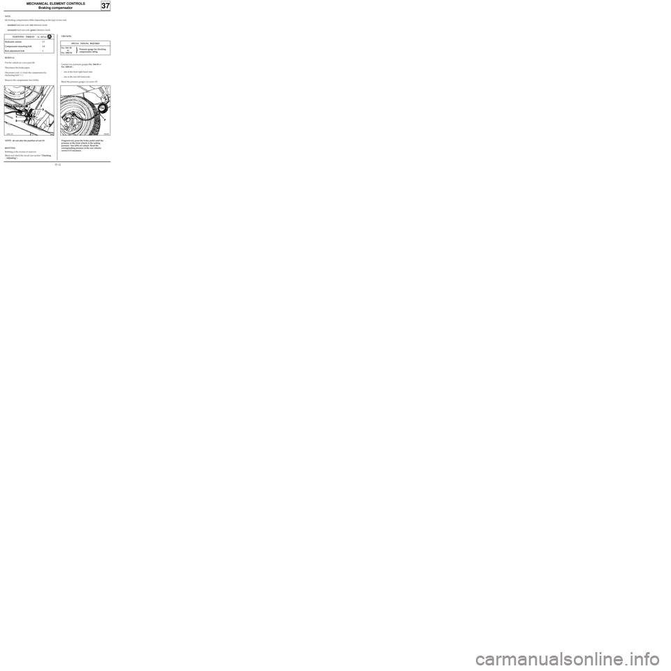
Disconnect rod ( 2 ) from the compensator by
slackening bolt ( 1 ).
Remove the compensator (two bolts).
12865-1R
TIGHTENING TORQUES (in daN.m)
Hydraulic unions 1.7
Compensator mounting bolt 1.8
Rod adjustment bolt 1
NOTE : do not alter the position of nut (3).
REFITTING
Refitting is the reverse of removal.
Bleed and check the circuit (see section "Checking
- Adjusting").
SPECIAL TOOLING REQUIRED
Fre. 244 -03
or
Fre. 1085-01
CHECKING
Connect two pressure gauges Fre. 244-03 or
Fre. 1085-01 :
- one at the front right hand side,
- one at the rear left hand side.
Bleed the pressure gauges via screw (P).
98828R
Progressively press the brake pedal until the
pressure at the front wheels is the setting
pressure (see table of values). Read the
corresponding pressure at the rear wheels;
correct it if necessary.Pressure gauge for checking
compensator rating
37-12
Page 92 of 105
MECHANICAL ELEMENT CONTROLS
External gear control
37
Mounting nut for unit on body 1.5
Linkage mounting clip bolt on clevice 2
Linkage mounting bolt on clevice 3
Linkage - lever mounting nut 3
TIGHTENING TORQUES (in daN.m)
REMOVAL
Disconnect the battery.
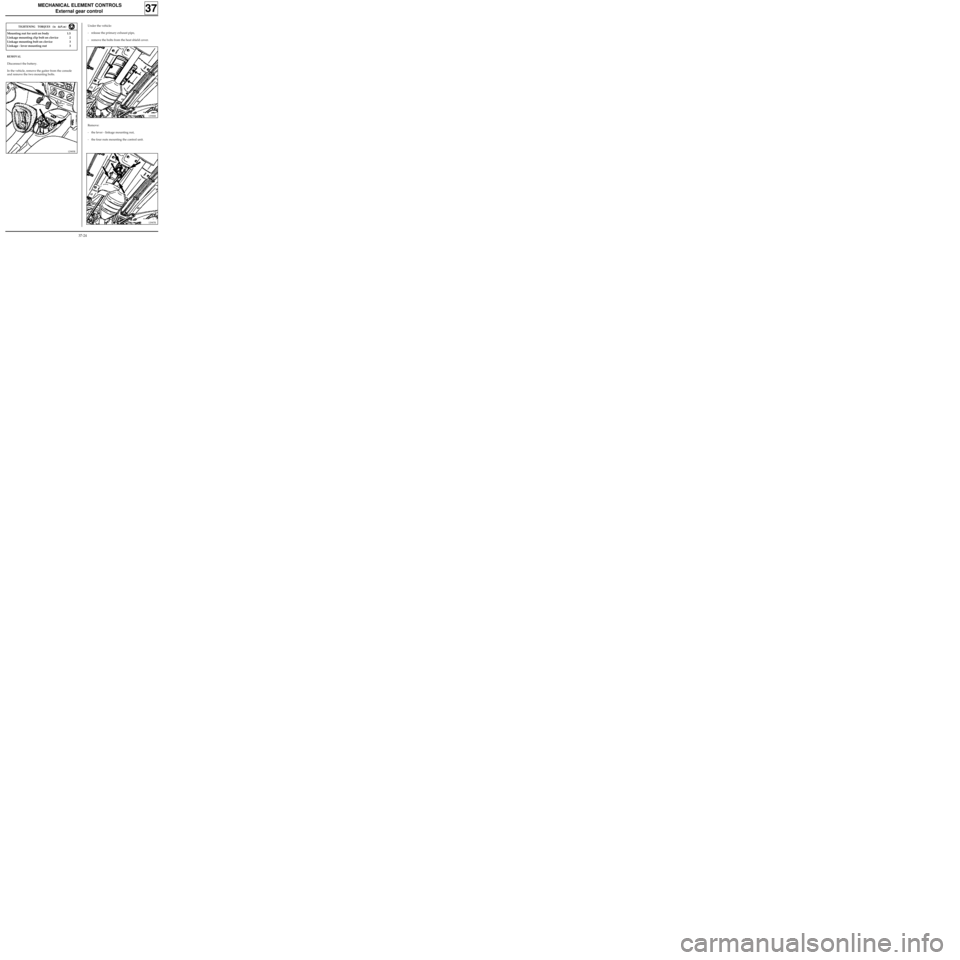
In the vehicle, remove the gaiter from the console
and remove the two mounting bolts.
12985R
Under the vehicle:
- release the primary exhaust pipe,
- remove the bolts from the heat shield cover.
12988R
Remove:
- the lever - linkage mounting nut,
- the four nuts mounting the control unit.
12987R
37-24
Page 94 of 105
93856-1S
MECHANICAL ELEMENT CONTROLS
External gear control
37
SPECIAL TOOLING REQUIRED
B.Vi. 1133 Shim for locking the gearbox input lever in 1st
Remove the collector.
Engage 1st gear.
TIGHTENING TORQUES (in daN.m)
ADJUSTMENT
Linkage mounting clip bolt on clevice 2
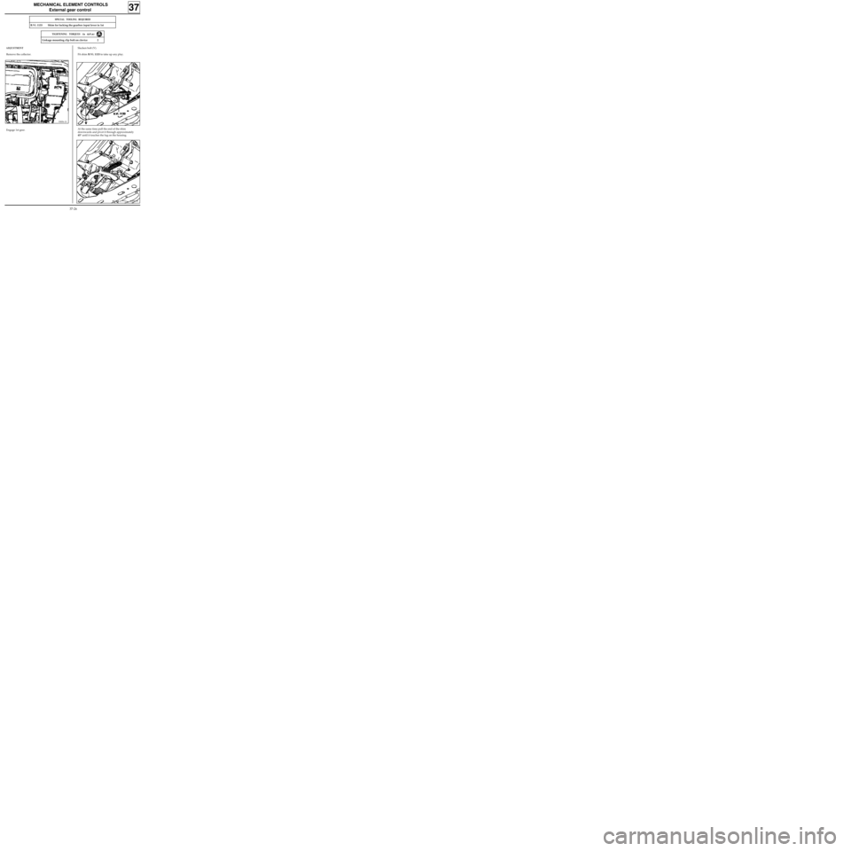
Slacken bolt (V).
Fit shim B.Vi. 1133 to take up any play.
92450-2R
At the same time pull the end of the shim
downwards and pivot it through approximately
45° until it touches the lug on the housing.
92450-3S
37-26
Page 103 of 105
ELECTRONICALLY CONTROLLED HYDRAULIC SYSTEMS
BOSCH ABS
38
13138R
Pipe unions M10 × 100 1.7
M12 × 100 1.7
TIGHTENING TORQUES (in daN.m)
REMOVAL
Put the vehicle on a two post lift.
Disconnect the battery.
Remove the front right hand wheel.
Fit a pedal press to limit the amount of brake
fluid which will run out.
From above:
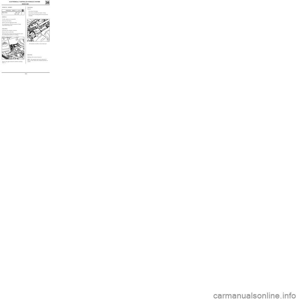
Disconnect the computer connector.
Remove the two earth bolts.
Disconnect the six pipes from the hydraulic assem-
bly, marking their position for refitting.
From below:
Remove:
- the exhaust downpipe,
- the exhaust manifold heat shield ( 3 bolts),
- the two lower mounting bolts for the hydraulic
assembly,HYDRAULIC ASSEMBLY
13139R
- the hydraulic assembly via the wheel arch.
Remove the upper hydraulic assembly mounting
bolt ( 1 ).
REFITTING
Refitting is the reverse of removal.
NOTE : the computer must not be removed. If
there is a fault, replace the complete hydraulic as-
sembly.
38-8
Page 104 of 105
ELECTRONICALLY CONTROLLED HYDRAULIC SYSTEMS
BOSCH ABS
38
HYDRAULIC BRAKING TEST
This section describes the test to be carried out using the XR25, to check the mounting of the ABS system in
the vehicle and, in particular, the hydraulic circuit.
NOTE: for this test, two persons are required and the vehicle must be on a two post lift, if possible.
Principle of the test
Put the vehicle on the lift with the wheel to be tested raised. One of the operators must be in the passenger
compartment in the driver’s position with the XR25. Switch the ignition on, vehicle in neutral, in fault finding
mode and press the brake pedal. The second operator must apply a torque to the wheel to try and rotate it.
The operator generates an appropriate command on the XR25 which carries out the following cycle ten
times: alternate decrease then increase in pressure at the wheel to be checked. These actions in the ABS will
be noted at the wheel as ten alternate locking and releasing operations. The jerky movement of the wheel,
noted qualitatively by the operator, signify that the hydraulic circuit for this wheel is correctly connected.
The programme for the XR25 for this sequence is as follows:
- Cycle on the wheel to be tested:
- a drop in pressure for 200 ms where the pump starts at the same time,
- an increase in pressure for 300 ms where the pump starts at the same time (ten cycles are carried out
for the wheel in question).
- The pressure increases to master cylinder pressure for all four wheels.
- The hydraulic pump motor stops.
- The operator releases the brake pedal.
The hydraulic test for the wheel in question is complete - begin the test for the three other wheels.
BLEEDING PROCEDURE
NOTE :
the hydraulic assembly is pre-filled.
This bleeding procedure must be used when one of the following components has been removed:
- the hydraulic assembly,
- the master cylinder,
- the pipework (between the hydraulic assembly and the master cylinder).
1)Bleed the braking system conventionally using the pedal.
NOTE : if, after a road test with ABS regulation, the pedal travel is not correct, bleed the hydraulic assembly.
38-9