RENAULT KANGOO 1997 KC / 1.G Engine And Peripherals User Guide
KANGOO 1997 KC / 1.G
RENAULT
RENAULT
https://www.carmanualsonline.info/img/7/1731/w960_1731-0.png
RENAULT KANGOO 1997 KC / 1.G Engine And Peripherals User Guide
Page 98 of 208
DIESEL EQUIPMENT
Location of components
13
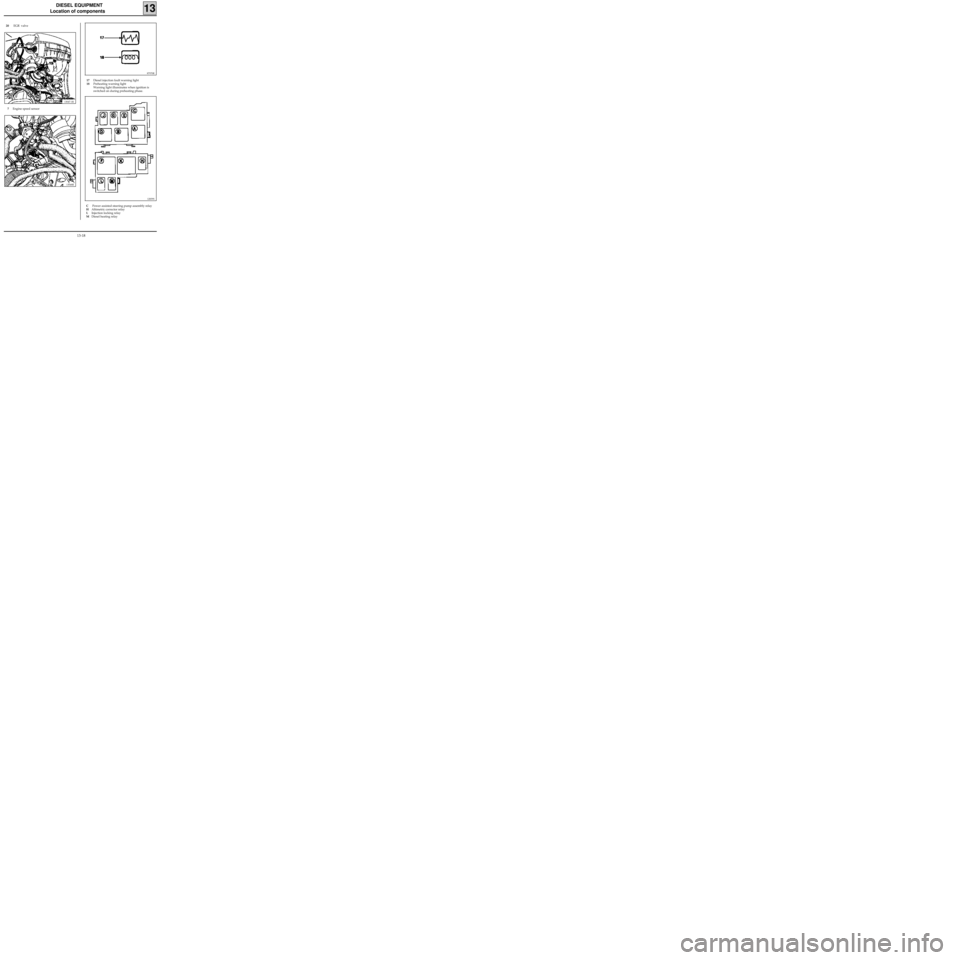
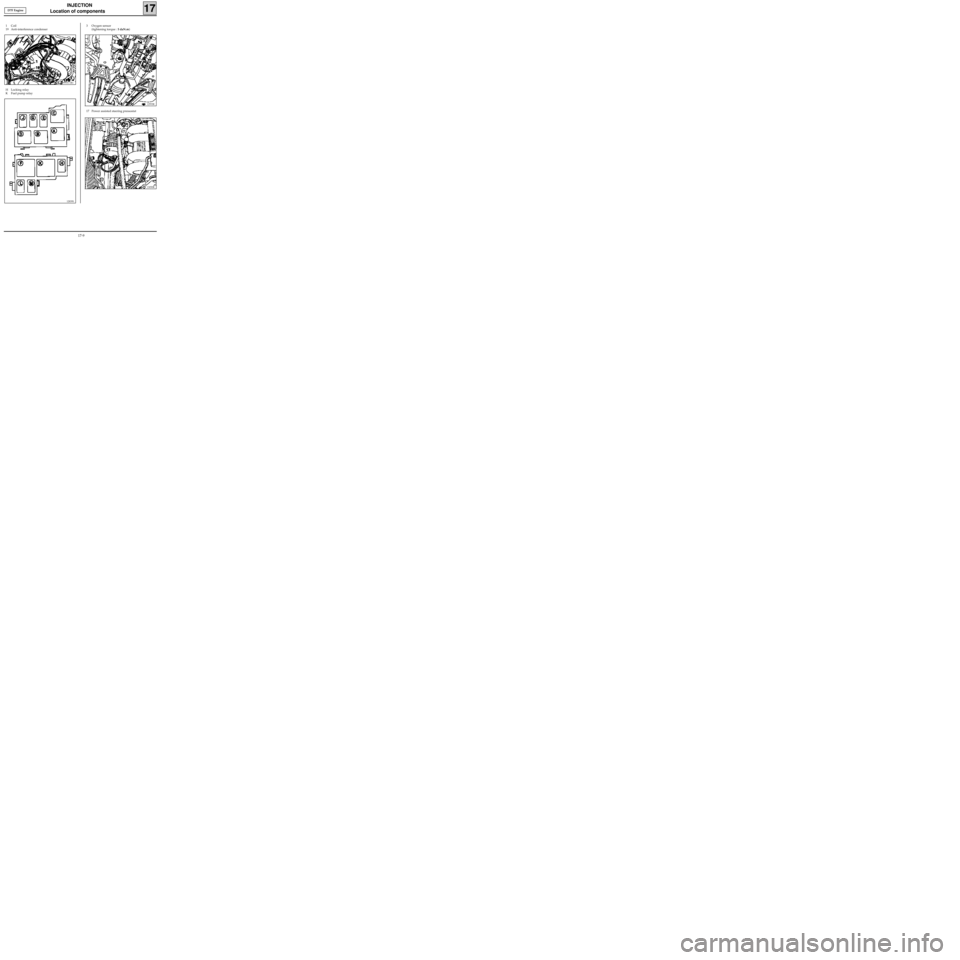
20 EGR valve
13047-1R
7Engine speed sensor
13048R
87970R
17Diesel injection fault warning light
18Preheating warning light
Warning light illuminates when ignition is
switched on during preheating phase.
12839S
C Power assisted steering pump assembly relay
HAltimetric corrector relay
LInjection locking relay
MDiesel heating relay
13-18
Page 117 of 208
DIESEL EQUIPMENT
Computer
13
PRM1316
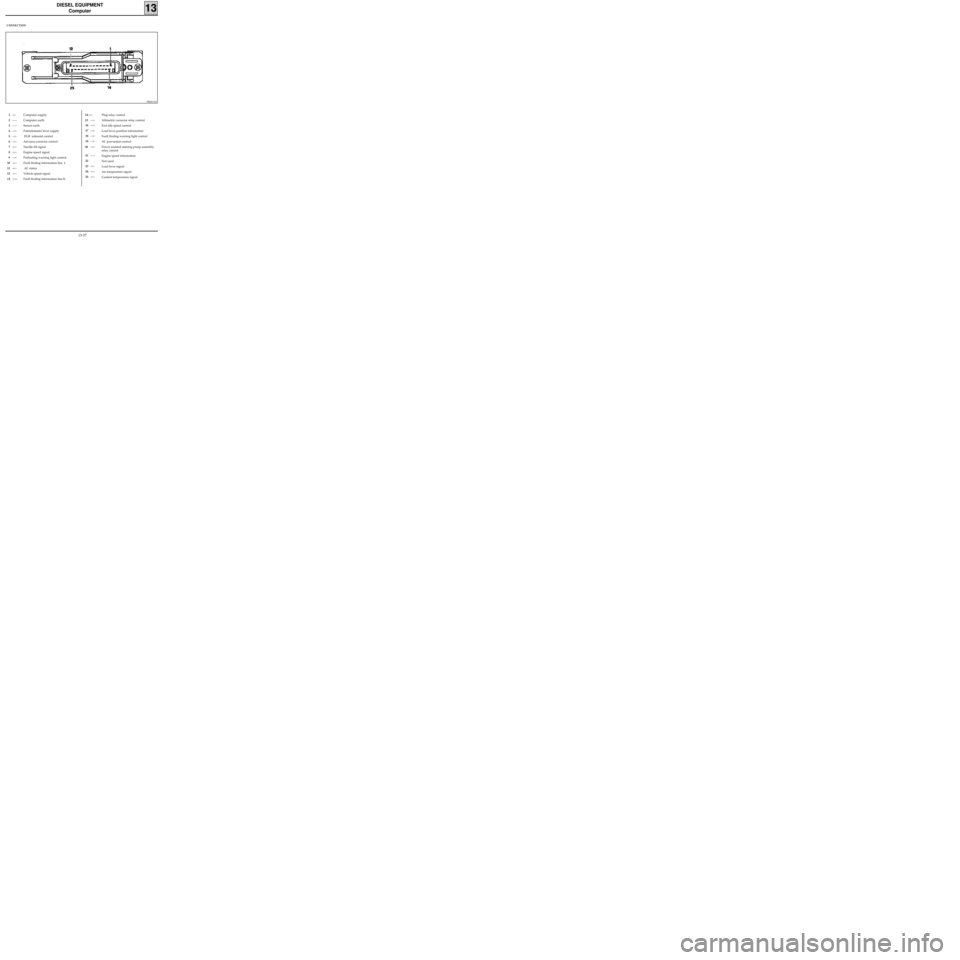
CONNECTION
1-<-
2-----
3-----
4-->-
5-->-
6-->-
7-<--
8-<--
9-->-
10-<--
11-<--
12-<--
13-><-Computer supply
Computer earth
Sensor earth
Potentiometer lever supply
EGR solenoid control
Advance corrector control
Needle lift signal
Engine speed signal
Preheating warning light control
Fault finding information line L
AC status
Vehicle speed signal
Fault finding information line KPlug relay control
Altimetric corrector relay control
Fast idle speed control
Load lever position information
Fault finding warning light control
AC prevention control
Power assisted steering pump assembly
relay control
Engine speed information
Not used
Load lever signal
Air temperature signal
Coolant temperature signal14-->-
15-->-
16-->-
17-->-
18-->-
19-->-
20 -->-
21-----
22
23-<--
24-<--
25-<--
13-37
Page 118 of 208
DIESEL EQUIPMENT
Defect modes
13
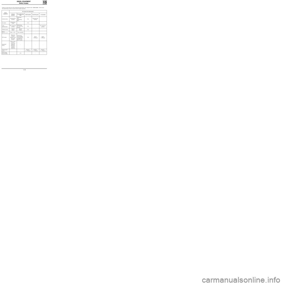
If there is a fault with one of the components listed below, the computer enters "defect mode", which means
that replacement values are used to ensure engine operation.
Faulty
componentSet values (for replacement)
Advance
corrector Pre-postheating
timeEGR function Fast idle speed AC function
Coolant sensorRunning time
functionPreheating : -
30°C
Postheating :
80°CCutRunning time
function-
Air sensorTemperature
= 22°C- Cut - -
Load
potentiometer100 % load lever
positionPostheating:
30 % load lever
position Cut - 20 % load lever
position
Altitude sensorAltitude
= 900 mAltitude
= 900 mCut - -
Battery
16 V < U < 6 VUbatt = 13.5V Not controlled - - -
TDC sensorMinimum
advance
Solenoid valve
fully open
position Postheating :
Not controlled
until ignition is
switched off
then on againCutSpeed
= 2 000 rpmSpeed
= 2 000 rpm
Needle lift
sensorDefect mode
advance
(Carto soft
F8Q 662)
Maximum
advance
(F8Q 630)----
Vehicle speed
sensor--Position :
V = 175 km/hPosition :
V = 175 km/hPosition :
V = 175 km/h
Heater plugs
relay housing- Cut - - -
13-38
Page 156 of 208
INJECTION
General
17
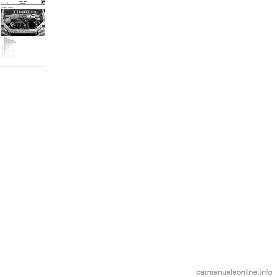
1 Coil
2 Air filter
3 Oxygen sensor
4 Absolute pressure sensor
5 Throttle position potentiometer
6 Idle regulation stepping motor
7 Air temperature sensor
8 Injection computer
9 Inertia switch
10 Locking relay
11 Fuel pump relay
12 TDC sensor
13 Fuel vapour recycling solenoid valve
14 Coolant temperature sensor
15 Tool for removing spark plug leads
16 Pinking sensor
17 Power assisted steering pressostat
18 Pressure regulator
19 Anti-interference condenser
20 Fuel vapour absorber (canister)
LOCATION OF COMPONENTS
13081
D7F Engine
17-6
Page 157 of 208
INJECTION
General
17
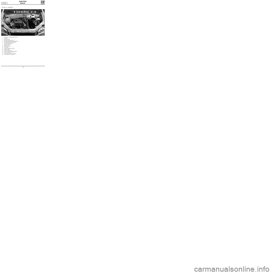
1 Fuel vapour recycling solenoid valve
2 Air filter
3 Pinking sensor
4 Absolute pressure sensor
5 Idle speed regulation stepping motor
6 Throttle position potentiometer
7 Air temperature sensor
8 Injection computer
9 Inertia switch
10 Fuel pump relay
11 TDC sensor
12 Coolant temperature sensor
13 Oxygen sensor
14 Coil for cylinders 2 - 3
15 Power assisted steering pressostat
16 Coil for cylinders 1 - 4
17 Fuel vapour absorber (canister)
18 Anti-interference condenser
LOCATION OF COMPONENTS
13082
E7J Engine
17-7
Page 159 of 208
INJECTION
Location of components
17
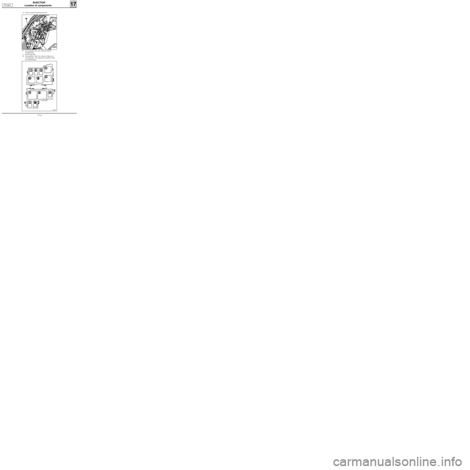
H Locking relay
K Fuel pump relay
3 Oxygen sensor
(tightening torque : 5 daN.m)
12993R
1 Coil
19 Anti-interference condenser
99931-1R1
12839S
17 Power assisted steering pressostat
13050R
D7F Engine
17-9
Page 162 of 208
INJECTION
Location of components
17
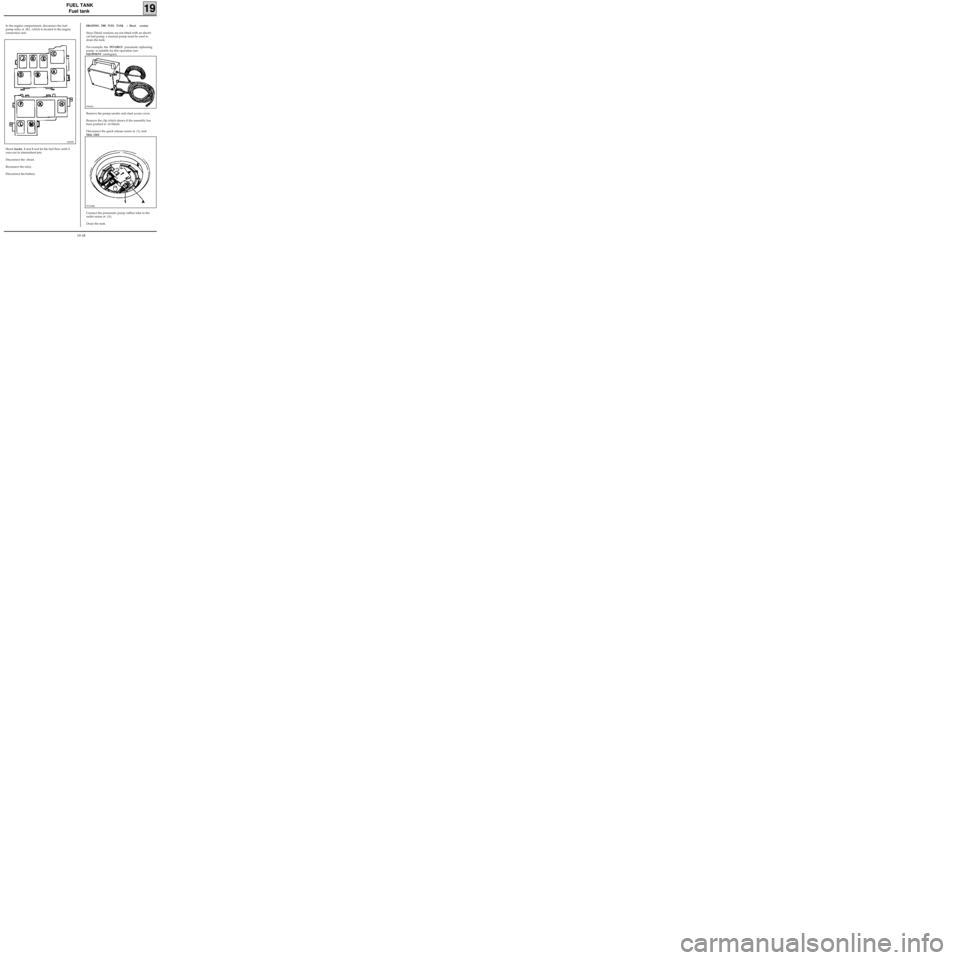
K Fan assembly relay (for versions with air
conditioning)
L Fuel pump relay
M Fan assembly relay (for versions without air
conditioning) slow speed fan assembly (with
air conditioning) 15 Power assisted steering pressostat
13241R
12839S
E7J engine
17-12
Page 192 of 208
FUEL TANK
Fuel tank
19
In the engine compartment, disconnect the fuel
pump relay at (K) , which is located in the engine
connection unit.
12839S
DRAINING THE FUEL TANK ( Diesel version)
Since Diesel versions are not fitted with an electri-
cal fuel pump, a manual pump must be used to
drain the tank.
For example, the
INTAIRCO pneumatic siphoning
pump is suitable for this operation (see
EQUIPMENT catalogue),
Shunt tracks 3 and 5 and let the fuel flow until it
runs out in intermittent jets.
Disconnect the shunt.
Reconnect the relay.
Disconnect the battery.Remove the pump-sender unit steel access cover.
Remove the clip which shows if the assembly has
been pushed in (if fitted).
Disconnect the quick release union at (1), tool
Mot. 1265.
99641S
97163R2
Connect the pneumatic pump rubber tube to the
outlet union at (A).
Drain the tank.
19-18
