timing belt RENAULT KANGOO 1997 KC / 1.G Engine And Peripherals User Guide
[x] Cancel search | Manufacturer: RENAULT, Model Year: 1997, Model line: KANGOO, Model: RENAULT KANGOO 1997 KC / 1.GPages: 208
Page 42 of 208
TOP AND FRONT OF ENGINE
Timing belt
11
REFITTING
An arrow indicating the direction of rotation and
two dashes for setting are marked on the surface
of the belt .
Check that the engine is at the setting point.
Bring the belt markings in line with the sprocket
markings .
Observe the mounting direction for the belt and
begin to position it on the crankshaft sprocket.
Carry out the tensioning of the belt using tool
Mot. 1135-01, until the fitting value is obtained
(see section 07 "Timing belt tension ").
Tighten the nut (O) of the tension wheel to a tor-
que of 5 daN.m.
It is essential to tighten the nut of the tension
wheel to a torque of 5 daN. to avoid any slacke-
ning which may cause a deterioration in the en-
gine .
Refitting is the reverse of removal.
Refit the crankshaft pulley, being sure to tighten
the bolt to a torque of 2 daN.m with an angle of
68° ± 6°.
Refit and tension the accessories belts (see section
07 "Accessories belt tension").
Never refit a belt once removed , but replace it. E7J Engine
11-7
Page 43 of 208
TOP AND FRONT OF ENGINE
Timing belt
11
REMOVAL
Place the vehicle on a 2 post lift.
Disconnect the battery.
Remove :
- the front right hand wheel and the mud-
guard,
- the protective plastic covering over the sus-
pended engine mounting cover .
Fit the engine support tool.
SPECIAL TOOLING REQUIRED
Mot. 1054TDC pin
Mot. 1273 Tool for checking belt tension
EQUIPMENT REQUIRED
Engine support tool
14mm torx socket
13370S
Remove :
- the accessories belt,
- the suspended engine mounting cover.
13086R1
Wheel bolts 9
Crankshaft pulley bolt 2 + 115° ± 15°
Tension wheel nut 5
Bolt for suspended engine mounting
cover 6.2
Nut for suspended engine mounting cover 4.4
TIGHTENING TORQUES (in daN.m or/and°)
F8Q Engine
11-8
Page 44 of 208
TOP AND FRONT OF ENGINE
Timing belt
11
13095S
Adjusting the timing
Turn the crankshaft so that the camshaft timing
reference mark is visible through the timing win-
dow .
Remove the
TDC pin plug .
Fit the TDC pin, tool Mot. 1054.
12419R
Remove :
- the timing covers,
12518R
- the crankshaft pulley.
Slacken the tension wheel and remove the belt.
NOTE : Slackening the tension wheel bolt by
more than one turn may cause it to come loose . F8Q Engine
11-9
Page 45 of 208
TOP AND FRONT OF ENGINE
Timing belt
11
REFITTING
Check that the pin Mot. 1054 is in place.
Fit the timing belt by aligning the belt markings
with those of the camshaft, injection pump and
crankshaft sprockets.
13096R
Tension the timing belt by tightening a bolt ( A )
on the inner timing housing.
Fit tool Mot. 1273 and tension the belt until the
fitting value is reached (see section 07 "Timing
belt tension").
13094R
Tighten the tension wheel nut to 5 daN.m.
NOTE : it is essential to tighten the tension wheel
nut to a torque of 5 daN.m to avoid any slacke-
ning which may bring about a deterioration in the
engine.
Replace the crankshaft pulley bolt.
Refit the crankshaft pulley , being sure to tighten
the bolt to a torque of 2 daN.m with an angle of
115° ± 15°.
Refitting is the reverse of removal.
Refit the accessories belt (see section 07
"Accessories belt tension").
NOTE : Never refit a belt once it has been remo-
ved, but replace it.
F8Q Engine
11-10
Page 46 of 208
12mm torx socket
Angular tightening wrench
TOP AND FRONT OF ENGINE
Cylinder head gasket
11
SPECIAL TOOLING REQUIRED
Mot. 591-04 Angle wrench for tightening
cylinder head and index
Mot. 1202 Hose clip pliers
Mot. 1273 Tool for checking belt tension
Mot. 1379 Tool for securing engine to
subframe
EQUIPMENT REQUIRED
TIGHTENING TORQUES (in daN.m)
Crankshaft output mounting bolt 2 + 90°
Mounting bolt for front right suspended
engine mounting on engine 6.2
Mounting bolt for front right suspended
engine mounting on vehicle body 6.2
Timing belt tension wheel nut 5
Wheel bolts 9
REMOVAL
Put the vehicle on a 2 post lift.
Remove the bonnet, and the right hand wheel .
Disconnect the battery.
Drain the cooling circuit.
Fit the engine support tool, Mot. 1379.Remove:
- the timing belt (see method described in
section 11 "Timing belt"),
- the dipstick,
- the brake servo pipe,
- the air filter,
- the accelerator cable,
- the fuel supply and return pipes level with the
timing belt cover on the cylinder head
D7F Engine
11-11
Page 50 of 208
TOP AND FRONT OF ENGINE
Cylinder head gasket
11
99902S
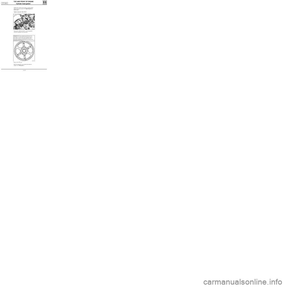
Tighten the cylinder head using an angular tighte-
ning wrench (see section 07 "Tightening the cy-
linder head").
Tighten using tool Mot. 591-04.
Line up the reference marks on the timing belt
with the markings on the sprockets.
10072S
Remove the TDC pin .
Refit the timing belt (see method described in
chapter 11 "Timing belt "). D7F Engine
IMPORTANT: The camshaft sprocket bears five
markings, of which only the rectangular one on
the surface of one of the teeth represents TDC;
the other markings are intended as an aid for ad-
justing the valve rockers.
11-15
Page 52 of 208
TOP AND FRONT OF ENGINE
Cylinder head gasket
11
SPECIAL TOOLING REQUIRED
DEPOSE
Place the vehicle on a 2 post lift .
Disconnect the battery.
Remove :
- the bonnet ,
- the timing belt (see method described in sec-
tion 11, "Timing belt ").
Drain the cooling circuit through the lower radia-
tor hose.
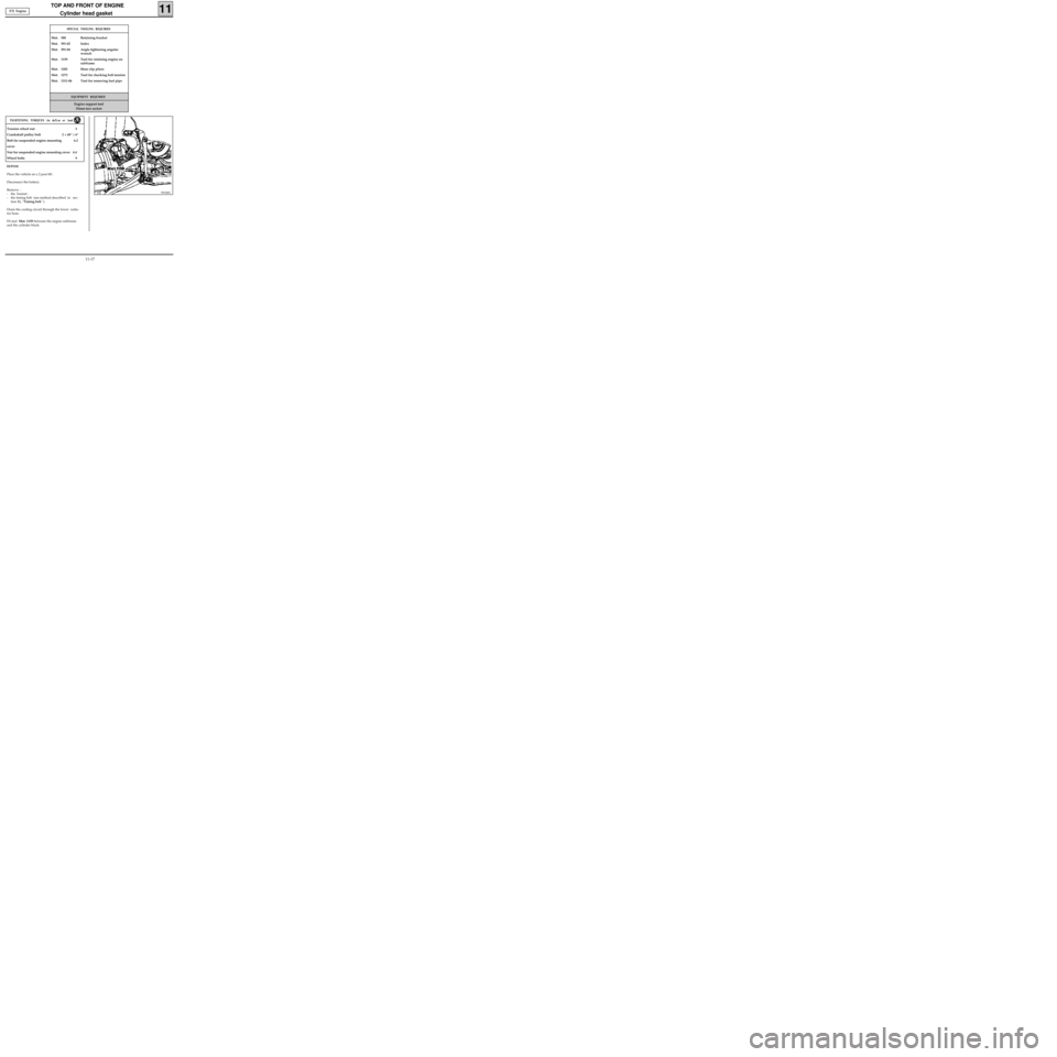
Fit tool Mot. 1159 between the engine subframe
and the cylinder block.
99024R2
EQUIPMENT REQUIRED
Engine support tool
55mm torx socket
Mot. 588 Retaining bracket
Mot. 591-02 Index
Mot. 591-04 Angle tightening angular
wrench
Mot. 1159 Tool for retaining engine on
subframe
Mot. 1202 Hose clip pliers
Mot. 1273 Tool for checking belt tension
Mot. 1311-06 Tool for removing fuel pipe
Tension wheel nut 5
Crankshaft pulley bolt 2 + 68° ± 6°
Bolt for suspended engine mounting 6.2
cover
Nut for suspended engine mounting cover 4.4
Wheel bolts 9
TIGHTENING TORQUES (in daN.m or /and °)
E7J Engine
11-17
Page 56 of 208
TOP AND FRONT OF ENGINE
Cylinder head gasket
11
CHECKING THE GASKET FACE
Check for gasket face bow, using a straight edge
and a set of shims.
Maximum deformation: 0.05 mm.
No regrinding of the cylinder head is permitted.
REFITTING (special notes)
Remove the cylinder liner brackets Mot. 588.
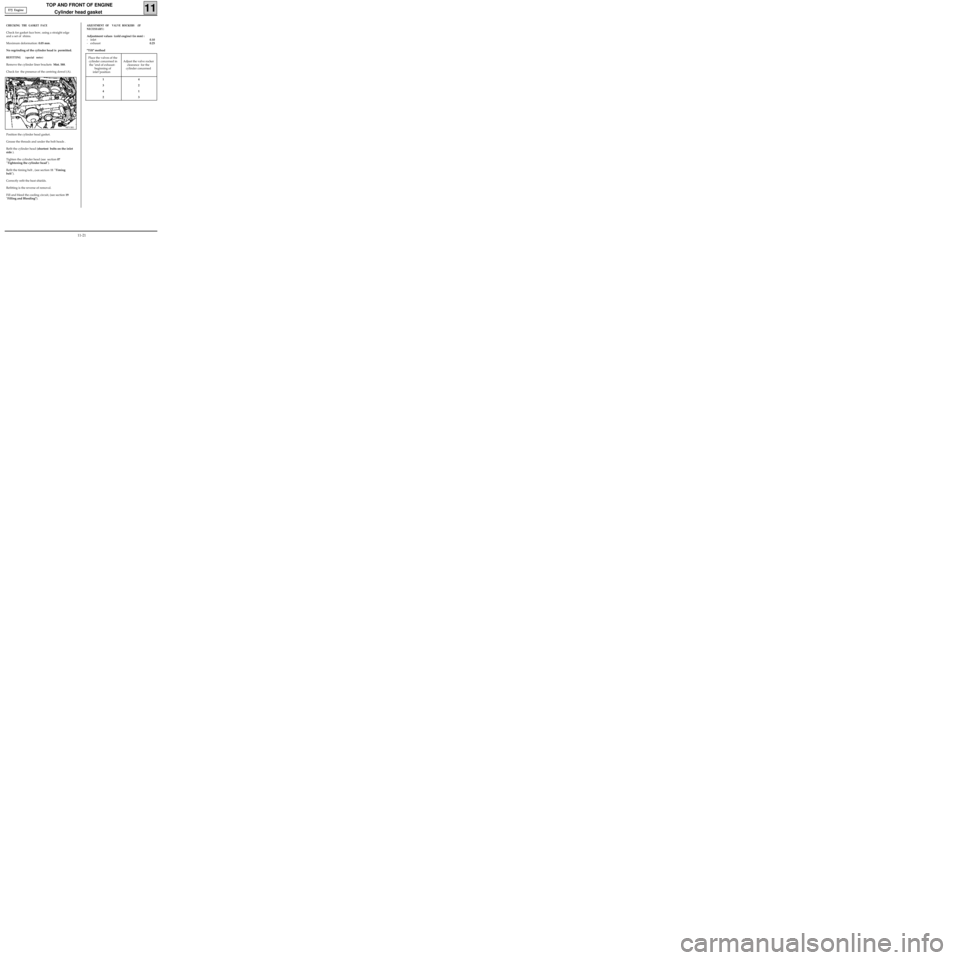
Check for the presence of the centring dowel (A).
98713R1
Position the cylinder head gasket.
Grease the threads and under the bolt heads .
Refit the cylinder head (shortest bolts on the inlet
side ).
Tighten the cylinder head (see section 07
"Tightening the cylinder head").
Refit the timing belt , (see section 11 "Timing
belt").
Correctly refit the heat shields.
Refitting is the reverse of removal.
Fill and bleed the cooling circuit, (see section 19
"Filling and Bleeding").
ADJUSTMENT OF VALVE ROCKERS (IF
NECESSARY)
Adjustment values (cold engine) (in mm) :
- inlet0.10
- exhaust0.25
"Tilt" method
E7J Engine
Place the valves of the
cylinder concerned in
the "end of exhaust-
beginning of
inlet"position Adjust the valve rocker
clearance for the
cylinder concerned
14
32
41
23
11-21
Page 58 of 208
TOP AND FRONT OF ENGINE
Cylinder head gasket
11
SPECIAL TOOLING REQUIRED
REMOVAL
Place the vehicle on a two post lift .
Disconnect the battery.
Remove :
- the bonnet,
- the timing belt (see method described in
section 11 "Timing belt").
Drain the cooling circuit via the lower radiator
hose.
EQUIPMENT REQUIRED
Engine support tool
55mm torx socket
Mot. 251-01 Dial gauge support tool
Mot. 252-01 Plate for measuring piston
protrusion
Mot. 591-02 Index
Mot. 591-04 Angular tightening wrench
Mot. 1054
TDC pin
Mot. 1159 Tool for mounting engine on
subframe
Mot. 1202 Hose clip pliers
Mot. 1273 Tool for checking belt tension
Mot. 1311-06 Tool for removing fuel pipe
Tension wheel nut 5
Crankshaft pulley bolt 2 + 115° ± 15°
Bolt for suspended engine mounting cover 6.2
Nut for suspended engine mounting cover 4.4
Wheel bolts 9
TIGHTENING TORQUES (in daN.m or/and°)
99024R2
Fit tool Mot. 1159 between the subframe and
the cylinder block. F8Q Engine
11-23
Page 61 of 208
TOP AND FRONT OF ENGINE
Cylinder head gasket
11
11733R
Remove the fuel pipe support (7).
Slacken the mounting bolts for the lower timing
cover, without removing them.
99173-1R
13093R
Remove :
- the accessories belt tensioning system,
- the cylinder head bolts.
Release the cylinder head by setting aside the
lower part of the lower camshaft housing,
without causing the cylinder head to pivot, since
this is centred by the two dowels at ( C ).
Using a syringe, extract any oil which may have
entered the cylinder head mounting holes .
This is necessary in order to obtain the correct
tightening of the bolts.
Protect the oil outlet duct in order to prevent any
foreign bodies from entering the oilways in the
cylinder head.
Failure to take this advice could lead to the
blocking of the oilways, resulting in a rapid dete-
rioration of the camshaft. F8Q Engine
11-26