belt RENAULT KANGOO 1997 KC / 1.G Engine And Peripherals Owner's Manual
[x] Cancel search | Manufacturer: RENAULT, Model Year: 1997, Model line: KANGOO, Model: RENAULT KANGOO 1997 KC / 1.GPages: 208
Page 56 of 208
TOP AND FRONT OF ENGINE
Cylinder head gasket
11
CHECKING THE GASKET FACE
Check for gasket face bow, using a straight edge
and a set of shims.
Maximum deformation: 0.05 mm.
No regrinding of the cylinder head is permitted.
REFITTING (special notes)
Remove the cylinder liner brackets Mot. 588.
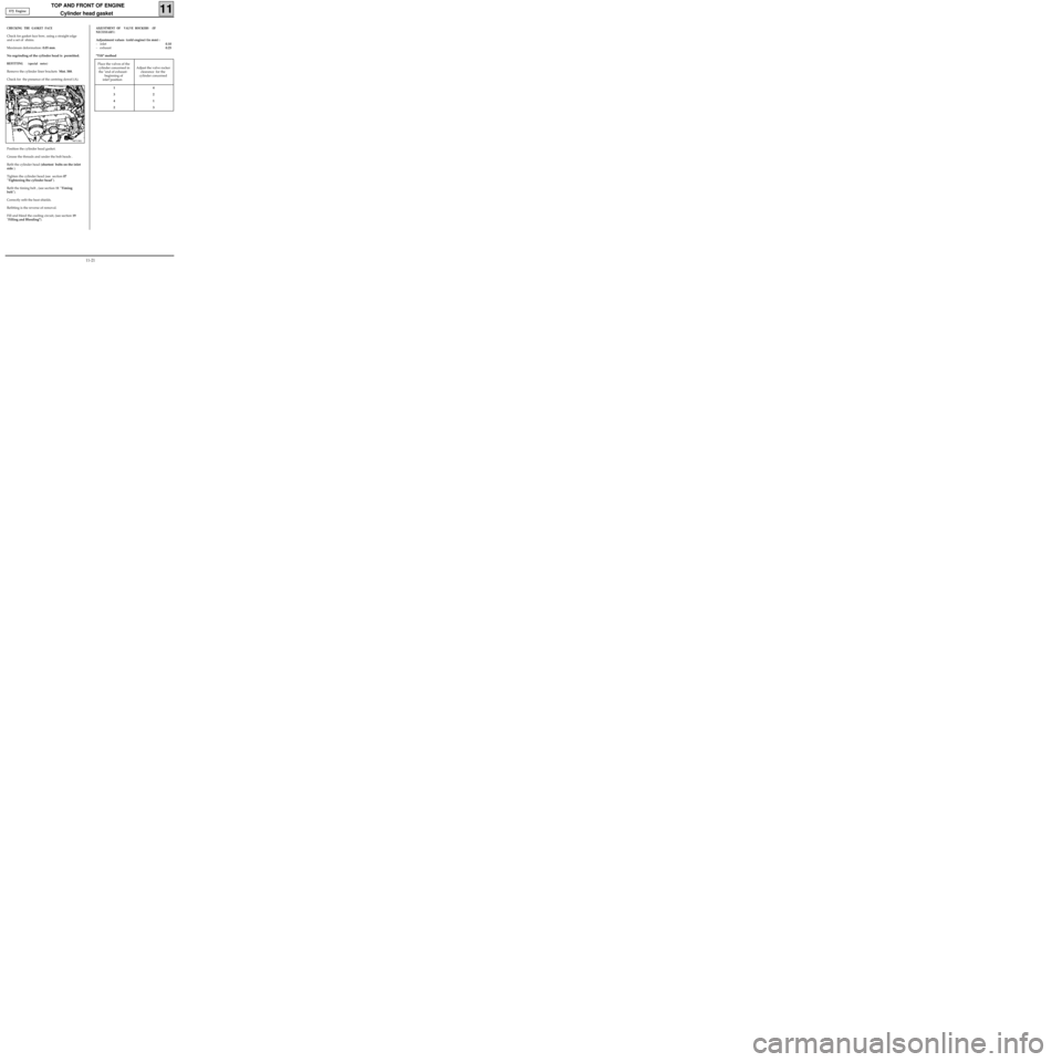
Check for the presence of the centring dowel (A).
98713R1
Position the cylinder head gasket.
Grease the threads and under the bolt heads .
Refit the cylinder head (shortest bolts on the inlet
side ).
Tighten the cylinder head (see section 07
"Tightening the cylinder head").
Refit the timing belt , (see section 11 "Timing
belt").
Correctly refit the heat shields.
Refitting is the reverse of removal.
Fill and bleed the cooling circuit, (see section 19
"Filling and Bleeding").
ADJUSTMENT OF VALVE ROCKERS (IF
NECESSARY)
Adjustment values (cold engine) (in mm) :
- inlet0.10
- exhaust0.25
"Tilt" method
E7J Engine
Place the valves of the
cylinder concerned in
the "end of exhaust-
beginning of
inlet"position Adjust the valve rocker
clearance for the
cylinder concerned
14
32
41
23
11-21
Page 58 of 208
TOP AND FRONT OF ENGINE
Cylinder head gasket
11
SPECIAL TOOLING REQUIRED
REMOVAL
Place the vehicle on a two post lift .
Disconnect the battery.
Remove :
- the bonnet,
- the timing belt (see method described in
section 11 "Timing belt").
Drain the cooling circuit via the lower radiator
hose.
EQUIPMENT REQUIRED
Engine support tool
55mm torx socket
Mot. 251-01 Dial gauge support tool
Mot. 252-01 Plate for measuring piston
protrusion
Mot. 591-02 Index
Mot. 591-04 Angular tightening wrench
Mot. 1054
TDC pin
Mot. 1159 Tool for mounting engine on
subframe
Mot. 1202 Hose clip pliers
Mot. 1273 Tool for checking belt tension
Mot. 1311-06 Tool for removing fuel pipe
Tension wheel nut 5
Crankshaft pulley bolt 2 + 115° ± 15°
Bolt for suspended engine mounting cover 6.2
Nut for suspended engine mounting cover 4.4
Wheel bolts 9
TIGHTENING TORQUES (in daN.m or/and°)
99024R2
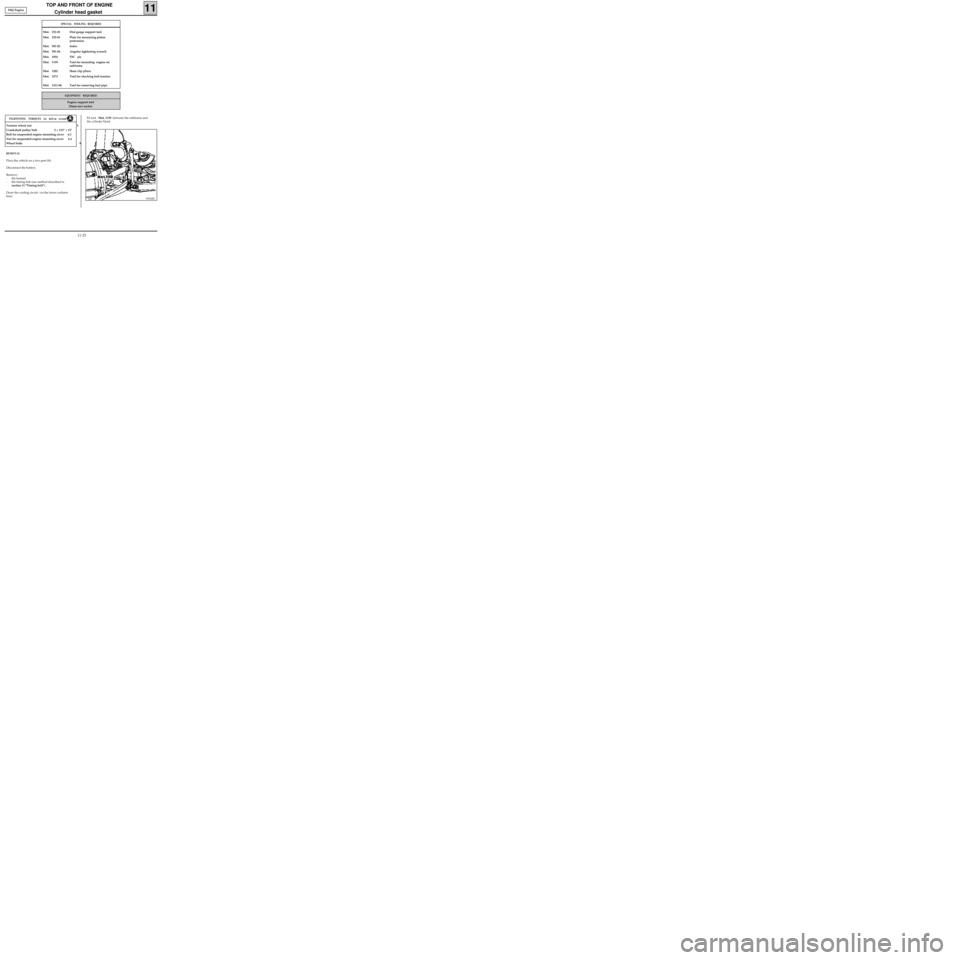
Fit tool Mot. 1159 between the subframe and
the cylinder block. F8Q Engine
11-23
Page 61 of 208
TOP AND FRONT OF ENGINE
Cylinder head gasket
11
11733R
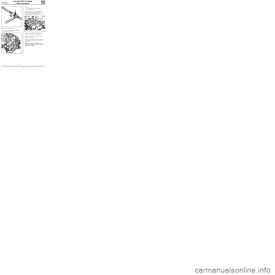
Remove the fuel pipe support (7).
Slacken the mounting bolts for the lower timing
cover, without removing them.
99173-1R
13093R
Remove :
- the accessories belt tensioning system,
- the cylinder head bolts.
Release the cylinder head by setting aside the
lower part of the lower camshaft housing,
without causing the cylinder head to pivot, since
this is centred by the two dowels at ( C ).
Using a syringe, extract any oil which may have
entered the cylinder head mounting holes .
This is necessary in order to obtain the correct
tightening of the bolts.
Protect the oil outlet duct in order to prevent any
foreign bodies from entering the oilways in the
cylinder head.
Failure to take this advice could lead to the
blocking of the oilways, resulting in a rapid dete-
rioration of the camshaft. F8Q Engine
11-26
Page 63 of 208
TOP AND FRONT OF ENGINE
Cylinder head gasket
11
REFITTING (special notes)
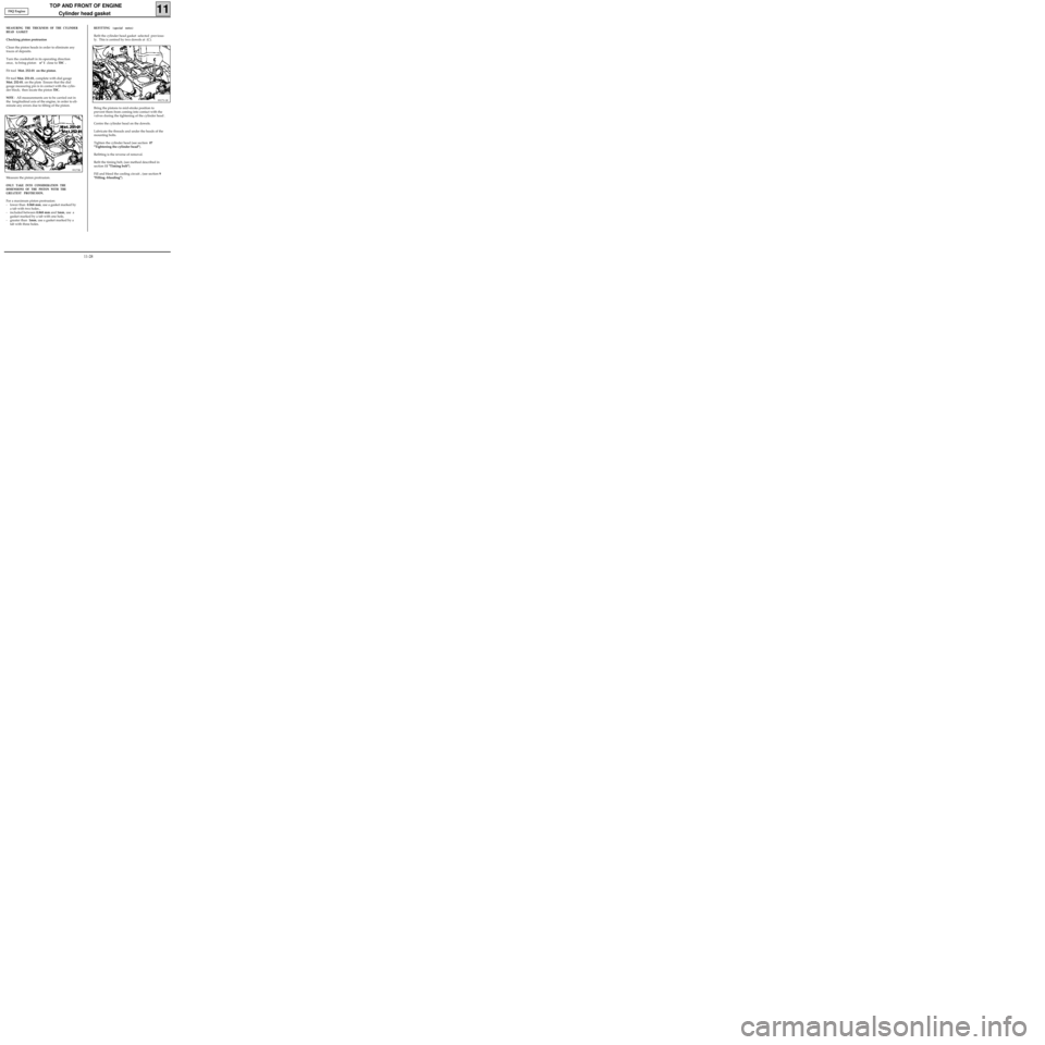
Refit the cylinder head gasket selected previous-
ly. This is centred by two dowels at (C).
99173-1R
Bring the pistons to mid-stroke position to
prevent them from coming into contact with the
valves during the tightening of the cylinder head .
Centre the cylinder head on the dowels.
Lubricate the threads and under the heads of the
mounting bolts.
Tighten the cylinder head (see section 07
"Tightening the cylinder head").
Refitting is the reverse of removal.
Refit the timing belt, (see method described in
section 11 "Timing belt").
Fill and bleed the cooling circuit , (see section 9
"Filling -bleeding").
MEASURING THE THICKNESS OF THE CYLINDER
HEAD GASKET
Checking piston protrusion
Clean the piston heads in order to eliminate any
traces of deposits.
Turn the crankshaft in its operating direction
once, to bring piston n° 1 close to
TDC .
Fit tool Mot. 252-01 on the piston.
Fit tool Mot. 251-01, complete with dial gauge
Mot. 252-01. on the plate Ensure that the dial
gauge measuring pin is in contact with the cylin-
der block; then locate the piston
TDC.
NOTE
: All measurements are to be carried out in
the longitudinal axis of the engine, in order to eli-
minate any errors due to tilting of the piston.
99173R
Measure the piston protrusion.
ONLY TAKE INTO CONSIDERATION THE
DIMENSIONS OF THE PISTON WITH THE
GREATEST PROTRUSION.
For a maximum piston protrusion:
- lower than 0.868 mm, use a gasket marked by
a tab with two holes ,
- included between 0.868 mm and 1mm, use a
gasket marked by a tab with one hole,
- greater than 1mm, use a gasket marked by a
tab with three holes. F8Q Engine
11-28
Page 110 of 208
DIESEL EQUIPMENT
Computer configuration
13
COMPUTER CONFIGURATION IN RELATION TO AIR CONDITIONING.
For vehicles equipped with air conditioning , enter G50*3* on the XR25
For vehicles without air conditioning , enter G50*4* on the XR25 .
COMPUTER CONFIGURATION IN RELATION TO THE PAS (POWER ASSISTED STEERING PUMP ASSEMBLY)
The vehicle may have two types of PAS assembly :
-a
PAS assembly including a high pressure pump driven by a belt. In this case, the computer must be
configured without PAS : enter G50*9* on the
XR25,
-a
PAS assembly with a pump assembly which is driven electrically and controlled by the injection compu-
ter. ( this type of
PAS is fitted in all vehicles which are also equipped with AC). In this case, the computer
must be configured with PAS : enter G50*8* on the XR25.
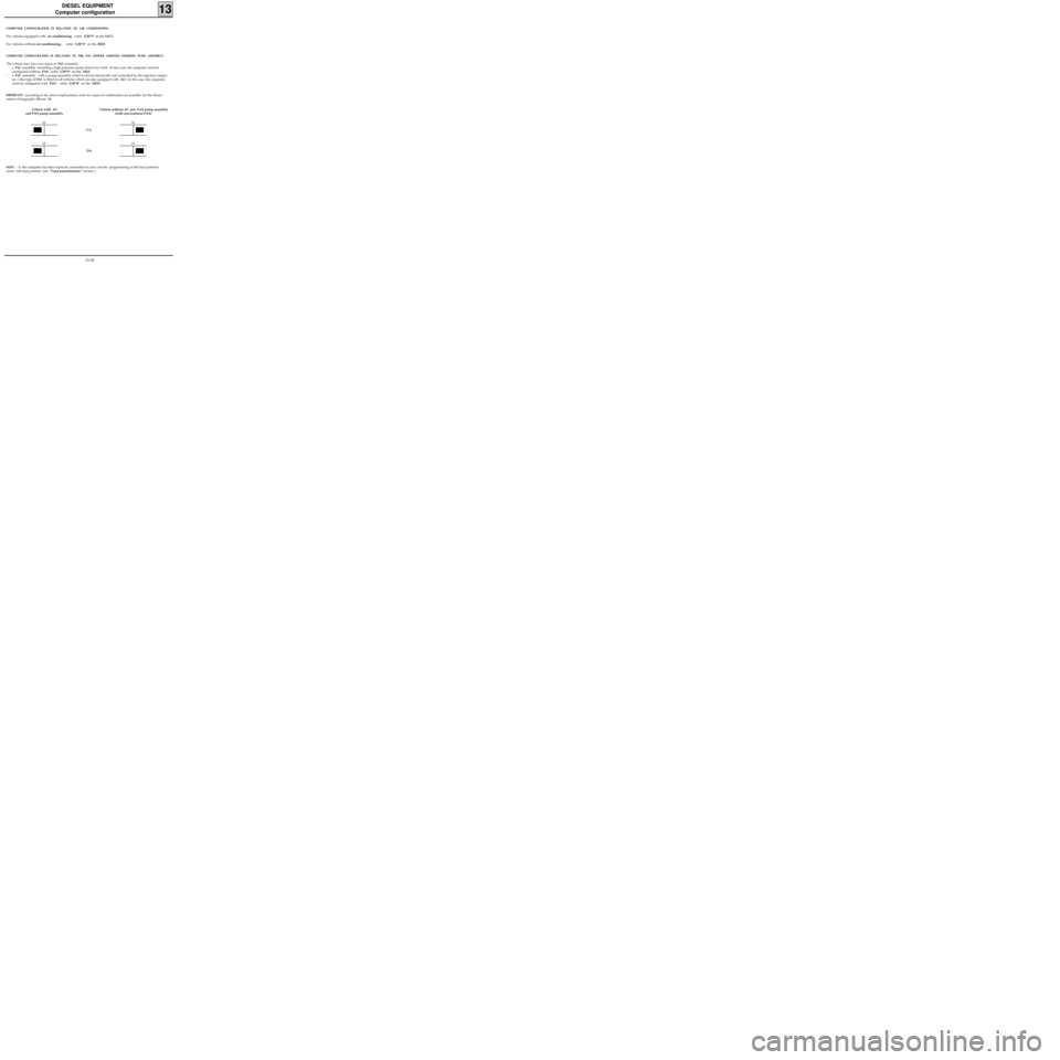
IMPORTANT : according to the above explanations, only two types of combination are possible for the illumi-
nation of bargraphs 18 and 19.
Vehicle with AC
and PAS pump assemblyVehicle without AC and PAS pump assembly
(with conventional PAS)
18
19
18
19
DA CA
NOTE : if the computer has been replaced, remember to carry out the programming of the load potentio-
meter full load position (see "Load potentiometer " section ).
13-30
Page 141 of 208
STARTING - CHARGING
Alternator
16
OPERATION - FAULT FINDING
These vehicles are equipped with alternators with
internal ventilation and integral regulator, also
with a warning light on the instrument panel
which has the following functions :
- when the ignition is switched on, the light illu-
minates
- when the engine is started the light extin-
guishes,
- if the light illuminates whilst the engine is
running there is a "charging "fault.
LOOKING FOR FAULTS
The warning light does not illuminate when the
ignition is switched on.
Check:
- all electrical connections are good.
- the bulb has not blown. (Earth the circuit and
the bulb should illuminate).
The warning light illuminates when the engine is
running.
This indicates a charging fault which could be
caused by :
- the alternator drive belt being broken or the
charging wiring being cut,
- internal alternator damage (rotor, stator,
diodes or brush),
- a regulator fault,
- excess voltage.The customer complains of a lack of charge and
the warning light is operating correctly.
If the regulated voltage is less than 13.5 V, check
the alternator. The fault could be caused by :
- a diode which has been damaged,
- a phase which is cut,
- contaminated or worn tracks.
Checking the voltage
Connect a voltmeter across the battery terminals
and read the battery voltage.
Start the engine and increase the engine speed
until the needle registers a stable regulated
voltage.
This voltage should be between 13.5 V and 14.8 V.
Connect as many consumers as possible, the
regulated voltage should be between 13.5 V and
14.8 V.
IMPORTANT: if arc welding work is to be carried
out on the vehicle, the battery and regulator
must be disconnected.
16-2
Page 143 of 208
STARTING - CHARGING
Alternator
16
If the electrical supply measured is too low, check:
- the wear of the alternator (brush...),
- the battery connections,
- the engine earth strap,
- the conformity of the alternator,
- the belt tension.
If the electrical supply measured is correct and the regulated voltage is too low, the alternator is not faulty.
The cause of the problem is to be attributed to one of the following sources :
- the vehicle has too many electrical consumers,
- the battery is discharged.
FAULT FINDING (continued)
16-4
Page 144 of 208
STARTING-CHARGING
Alternator
16
REMOVAL
Place the vehicle on a two post lift .
Disconnect the battery as well as all electrical
connections leading to the alternator.
Remove :
- the alternator belt and that of the power as-
sisted steering pump for the D7F engine (if
fitted),
- the alternator.
REFITTING
Refitting is the reverse of removal.
D7F Engine
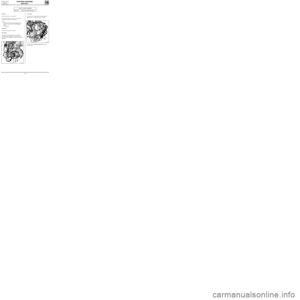
Tensioning of the alternator belt is carried out
using the locally manufactured tool shown be-
low (threaded rod 100 mm in length (X) and three
M6 nuts).
D7F / E7J
Engines
SPECIAL TOOLING REQUIRED
Mot. 1273 Tool for checking belt tension
10617R
E7J Engine
Tension the belt using the bolt at (1) and tighten
the nut at (2) , having measured the tension.
13363R
See section 07 "Accessories belt tension" for the
tension values.
16-5
Page 145 of 208
STARTING-CHARGING
Alternator
16
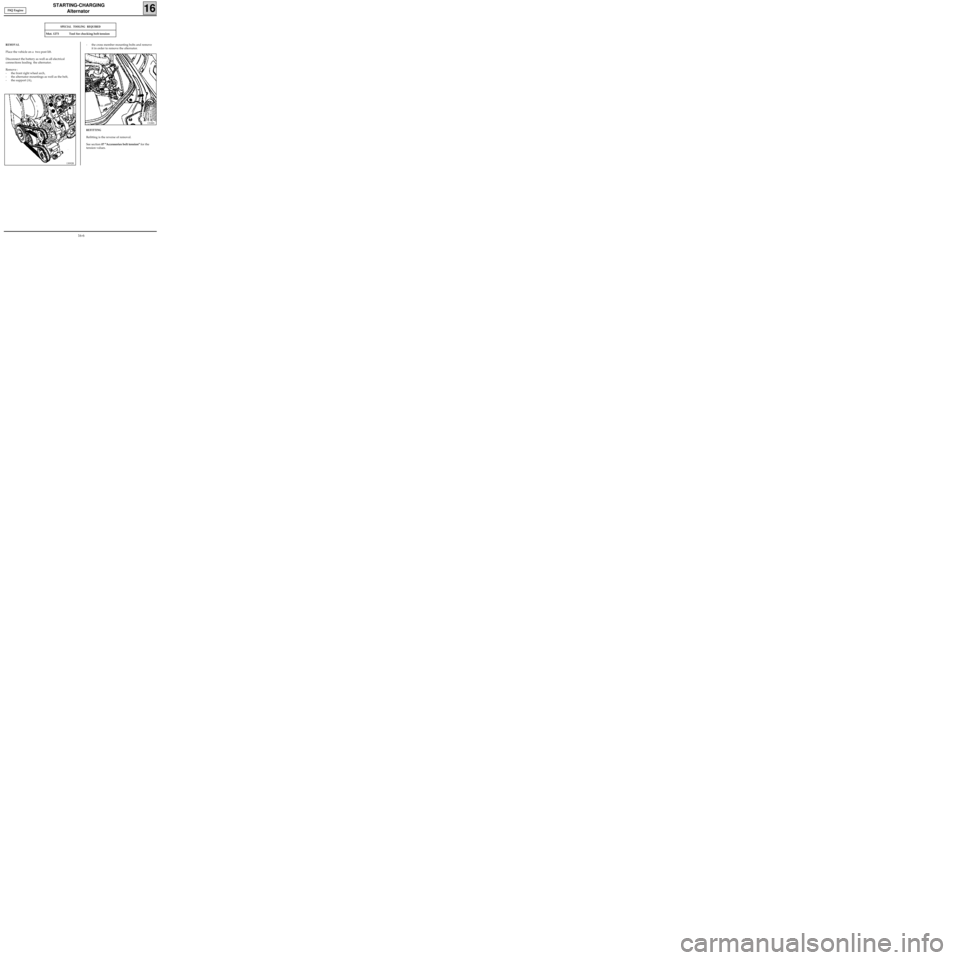
REMOVAL
Place the vehicle on a two post lift.
Disconnect the battery as well as all electrical
connections leading the alternator.
Remove :
- the front right wheel arch,
- the alternator mountings as well as the belt,
- the support (A),
SPECIAL TOOLING REQUIRED
Mot. 1273 Tool for checking belt tension
13092R
- the cross member mounting bolts and remove
it in order to remove the alternator.
13188S
REFITTING
Refitting is the reverse of removal.
See section 07 "Accessories belt tension" for the
tension values. F8Q Engine
16-6
Page 181 of 208
COOLING
Water pump
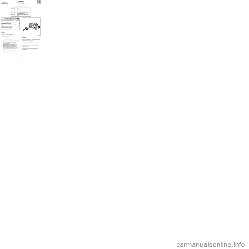
CLEANING
It is very important not to scratch the gasket faces
of all aluminium components.
Use the product Décapjoint to dissolve the part
of the gasket which remains attached.
Apply the product to the part to be cleaned, wait
approximately 10 minutes, then remove it using a
wooden spatula.
The wearing of gloves is recommended during
this operation.
19
SPECIAL TOOLING REQUIRED
Mot. 1054TDC pin
Mot. 1202 Hose clip pliers
Mot. 1273 Tool for checking belt tension
Mot. 1289-03 Tool for centring the suspended en-
gine movement limiter
Mot. 1379 Tool for retaining engine on sub-
frame
10478S
D7F Engine
Crankshaft output mounting bolts 2 + 90°
Bolt for mounting front right suspended
engine mounting on engine 6.2
Bolt for mounting front right suspended
engine mounting on vehicle body 6.2
Timing belt tension wheel nut 5
Water pump mounting bolt 0.9
TIGHTENING TORQUES (in daN.m)
REMOVAL
Place the vehicle on a two post lift.
Disconnect the battery.
Remove:
- the timing belt (see method described in
section 11 "Timing belt),
- the power assisted steering pump pulley (if fit-
ted),
- the upper alternator mounting bolt and
slacken the lower bolt,
- the bolts for mounting the power assisted
steering pipe on the cylinder block,
- the bolts for mounting the power assisted
steering pump on its support (move the po-
wer assisted steering pump-pipe assembly to
one side),
- the power assisted steering pump support,
- the water pump hose,
- the tension wheel along with the water pump
itself.
19-7