fuel pressure RENAULT KANGOO 1997 KC / 1.G Engine And Peripherals Owner's Manual
[x] Cancel search | Manufacturer: RENAULT, Model Year: 1997, Model line: KANGOO, Model: RENAULT KANGOO 1997 KC / 1.GPages: 208
Page 172 of 208
INJECTION
Adaptive richness correction
17
D7F
Engine
E7J
Engine
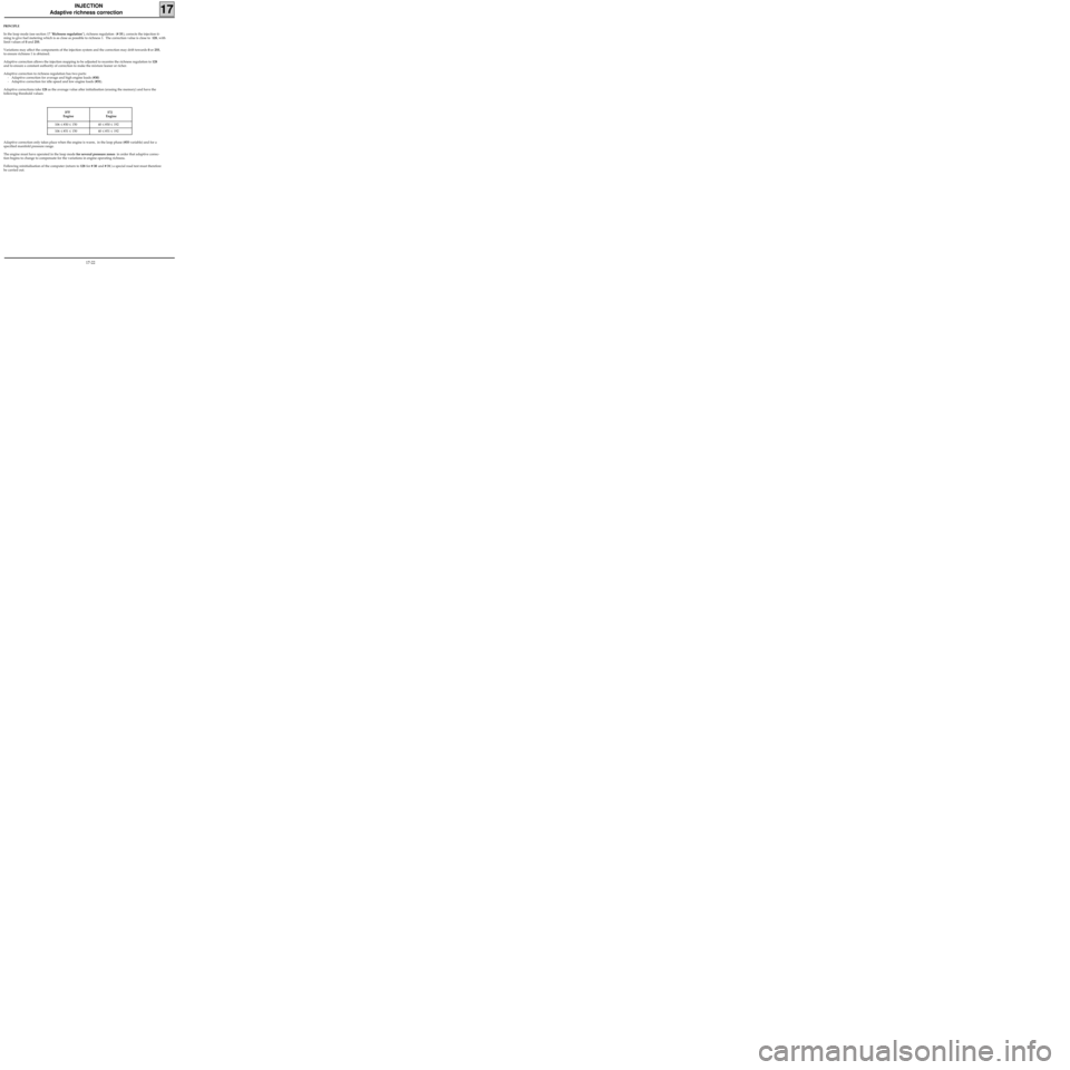
106 ≤ #30 ≤ 150 40 ≤ #30 ≤ 192
106 ≤ #31 ≤ 150 40 ≤ #31 ≤ 192
PRINCIPLE
In the loop mode (see section 17 "Richness regulation"), richness regulation (# 35), corrects the injection ti-
ming to give fuel metering which is as close as possible to richness 1. The correction value is close to 128, with
limit values of 0 and 255.
Variations may affect the components of the injection system and the correction may drift towards 0 or 255,
to ensure richness 1 is obtained.
Adaptive correction allows the injection mapping to be adjusted to recentre the richness regulation to 128
and to ensure a constant authority of correction to make the mixture leaner or richer.
Adaptive correction to richness regulation has two parts:
- Adaptive correction for average and high engine loads (#30)
- Adaptive correction for idle speed and low engine loads (#31).
Adaptive corrections take 128 as the average value after initialisation (erasing the memory) and have the
following threshold values:
Adaptive correction only takes place when the engine is warm, in the loop phase (#35 variable) and for a
specified manifold pressure range.
The engine must have operated in the loop mode for several pressure zones in order that adaptive correc-
tion begins to change to compensate for the variations in engine operating richness.
Following reinitialisation of the computer (return to 128 for # 30 and # 31) a special road test must therefore
be carried out.
17-22
Page 174 of 208
INJECTION
Adaptive richness correction
17
INTERPRETATION OF INFORMATION GATHERED DURING A ROAD TEST
If there is a lack of fuel (injectors dirty, fuel pressure and flow too low...), richness regulation # 35 increases to
obtain the richness as close as possible to richness 1 and adaptive correction # 30 and # 31 increases until the
richness correction returns to oscillate around 128.
If there is an excess of fuel, the situation is reversed : Richness regulation # 35 reduces and adaptive
correction # 30 and # 31 also reduces to recentre the richness correction (# 35) around 128.
NOTE : the analysis which may be made using # 31 remains difficult since this correction mainly operates for
idle speed and low loads and is also very sensitive.
Hasty conclusions should not therefore be drawn from this gate value, rather the position of # 30 should be
examined.
The information from these two gates gives an idea about the engine operation richness, and may be used as
a guide for fault finding. In order for these to be put to good use during fault finding, no conclusion may be
drawn from their value unless they are at the minimum or maximum correction limit, and if both gate values
were offset in the same direction.
IMPORTANT : # 30 and # 31 should only be examined and analysed after a customer complaint, an opera-
ting fault and if they are at the threshold with the value for # 35 also offset (# 35 varies above 175 or be-
low 80).
17-24
Page 201 of 208

FUEL TANK
Fuel tank
19
Components
1 Tank
2 Bolt
3 Filler neck
4 Filler neck bowl
5 Rivet
6 Sleeve mounting clip
7 Fuel cap
8 Fuel supply pipe
9 Fuel return pipe
10 Clip
13 Cup
14 Canister pipe
15 Canister pipe
18 Canister
19 Bolt
20 Clip
21 Clip
22 Damper pad
23 Captive nut
24 Connection between filler neck outlet and
fuel passage pipe
25 Degassing - filling
27 Canister connection (fuel vapours)
28 Over-filling prevention valve
29 Excess pressure-under-pressure safety valve
30 Restriction valve
31 Leak prevention valve in case vehicle turns
over
32 Over-filling prevention valve and leak pre-
vention valve in case vehicle turns over.
A Quick-release union
B Snap-fit union
C Quick release union
D Sleeve (not snap-fit)
E Opening for air outlet during filling
F Air volume allowing the fuel to expand
R Fuel inlet for filling
V Maximum fuel volume allowed.
19-27
Page 202 of 208
FUEL TANK
Fuel tank
19
PURPOSE OF THE VALVES
28 Overfill prevention valve
When the filler cap is removed the valve is
closed, trapping a volume of air within the
breather volume. This prevents fuel from fil-
ling this volume.
When the filler cap is replaced, the valve
opens allowing the tank to breathe through
the canister
29 Excess - vacuum safety valve
If the fuel vapour recirculation circuit is
blocked, this valve prevents the fuel tank
being subject to excess pressure (the tank
would inflate) or vacuum (as fuel is used, the
tank would be crushed).
30 Restriction valve
This valve prevents the introduction of leaded
fuel into the tank.
31 Leak prevention valve in case vehicle turns
over
If the vehicle turns over, this valve prevents
the tank from emptying, either through the
pipe leading to the canister, or through the
breather pipe (in Diesel versions).
32 Overfill prevention valve and leak prevention
valve in case the vehicle turns over
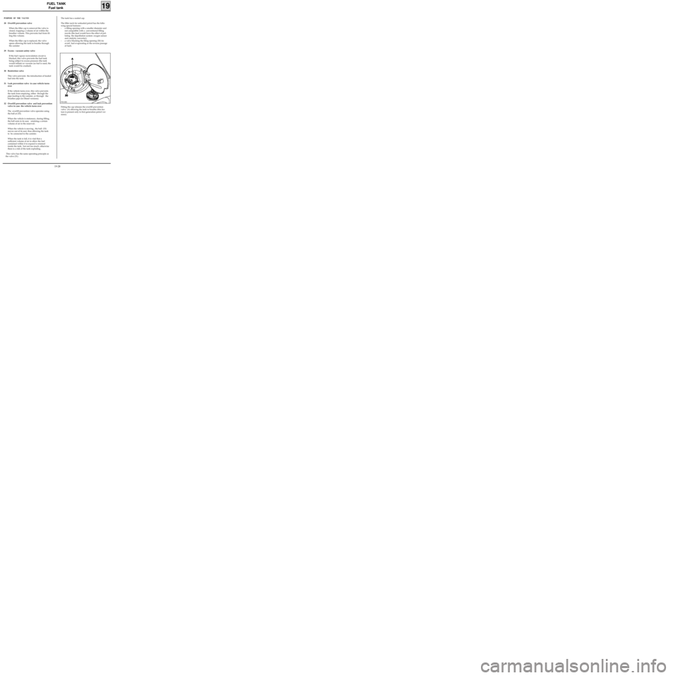
The overfill prevention valve operates using
the ball at (33).
When the vehicle is stationary, during filling,
the ball rests in its seat, retaining a certain
volume of air in the reservoir .
When the vehicle is moving , the ball (33)
moves out of its seat, thus allowing the tank
to be connected to the canister.
When the tank is full, it is vital that a
sufficient volume of air to allow the fuel
contained within it to expand is retained
inside the tank, but not too much, otherwise
there is a risk of the tank exploding .
This valve has the same operating principle as
the valve (31) .
The tank has a sealed cap.
The filler neck for unleaded petrol has the follo-
wing special features :
- a filling opening with a smaller diameter and
not compatible with a conventional filling
nozzle (the lead would have the effect of pol-
luting the depollution system: oxygen sensor
and catalytic converter),
- a valve blocking the filing opening (30) (to
avoid fuel evaporating or the reverse passage
of fuel).
Fitting the cap releases the overfill prevention
valve (A) allowing the tank to breathe (this fea-
ture is present only in first generation petrol ver-
sions).
99212R2
19-28
Page 204 of 208
Mot. 1264 Wrench for removing
Mot. 1264-01 pump-sender unit assembly nut
Mot. 1265 Pliers for removing
Mot. 1265-01 quick release unions
FUEL TANK
Pump- sender unit
19
SPECIAL TOOLING REQUIRED
IMPORTANT :
During all operations on the fuel tank or on the
fuel supply circuit , it is vital :
- to refrain from smoking and handling incan-
descent objects in the vicinity of the working
area,
- to avoid fuel projections, due to the residual
pressure present in the pipes during removal .
REMOVAL
To remove the pump-sender unit assembly, it is
not necessary to remove the tank, as it is accessi-
ble through the inside of the vehicle. To do this :
- disconnect the battery,
- lift the rear bench seat ,
- remove the steel access cover,
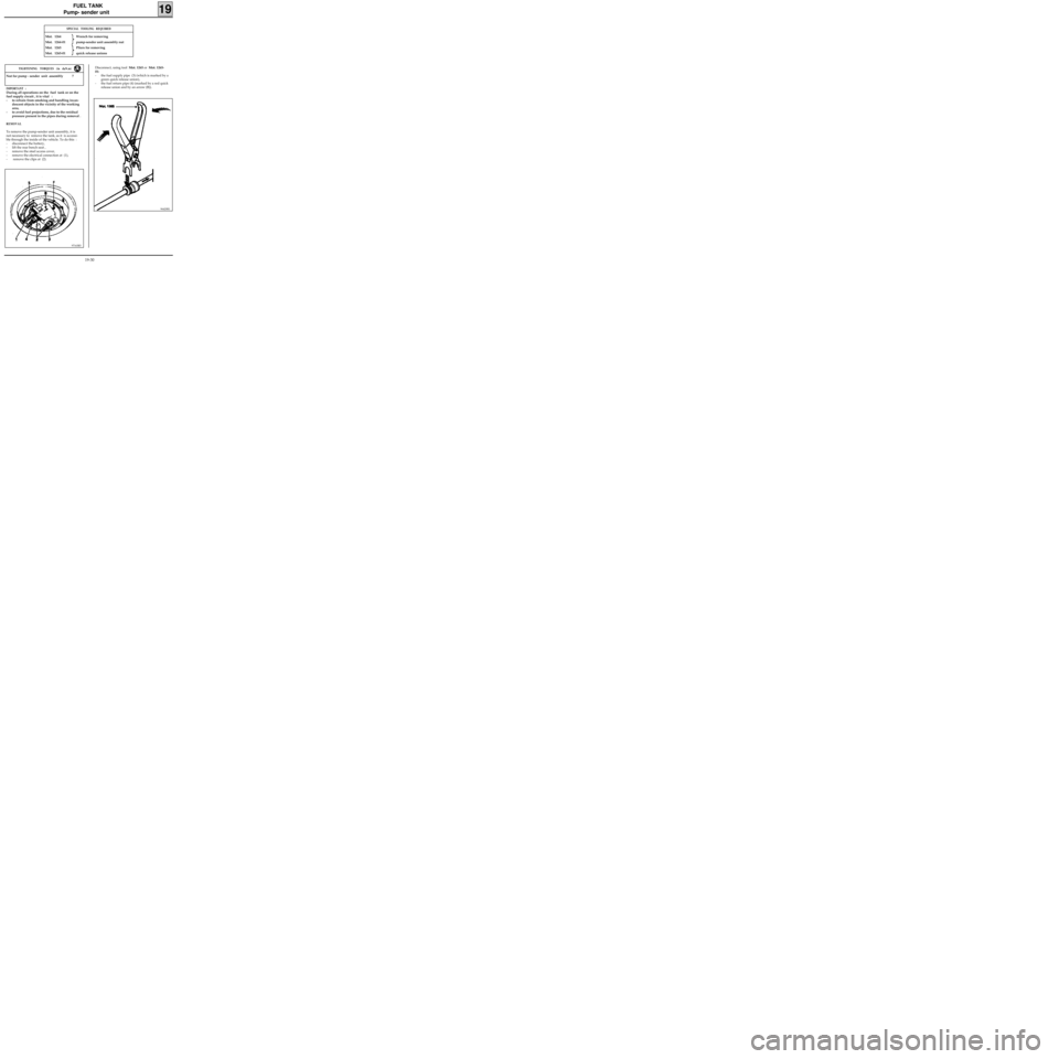
- remove the electrical connection at (1),
- remove the clips at (2).
97163R5
Nut for pump - sender unit assembly 7
TIGHTENING TORQUES (in daN.m)Disconnect, using tool Mot. 1265 or Mot. 1265-
01:
- the fuel supply pipe (3) (which is marked by a
green quick release union),
- the fuel return pipe (4) (marked by a red quick
release union and by an arrow (B)).
96420R1
19-30