battery RENAULT KANGOO 1997 KC / 1.G Engine And Peripherals Owner's Guide
[x] Cancel search | Manufacturer: RENAULT, Model Year: 1997, Model line: KANGOO, Model: RENAULT KANGOO 1997 KC / 1.GPages: 208
Page 168 of 208
INJECTION
Idle speed correction
17
CONNECTION BETWEEN THE POWER ASSISTED STEERING PRESSOSTAT AND THE INJECTION COMPUTER
The injection computer receives information from the power assisted steering pressostat . This varies
depending on the pressure present in the hydraulic circuit. The higher the pressure, , the more energy is
absorbed by the power assisted steering pump.
To compensate for this energy absorption, the injection computer increases the opening ratio of the idle
speed regulation stepping motor.
The information is received on track 13 of the injection computer. If the pressostat is closed , the computer
receives an earth . The idle speed is adjusted to 800 rpm for the D7F engine and 850 rpm for the E7J
engine .
IDLE SPEED CORRECTION DEPENDING ON THE BATTERY VOLTAGE
The objective of this correction is to compensate for the drop in voltage, due to consumer operation when
the battery is poorly charged To correct this, the idle speed is increased, allowing the alternator to rotate
faster and consequently increase the charging voltage.
The lower the voltage, the greater the degree of correction. Correction of the engine speed is therefore
variable. It begins when the voltage drops to below 12.7 Volts. Correction begins at the nominal engine
speed and may reach a maximum of 880 rpm for the D7F engine and 930 rpm for the
E7J engine .
IDLE SPEED CORRECTION DEPENDING ON AIR CONDITIONING OPERATION
The injection computer increases the idle speed to 850 rpm. for the D7F engine and 880 rpm . for the E7J
engine , provided it receives the fast idle speed information from the air conditioning computer.
17-18
Page 169 of 208
INJECTION
Adaptive idle speed correction
17
PRINCIPLE
Under normal warm engine operating conditions , the R.C.O. idle speed value at #12 varies between a
high value and a low value, until the nominal idle speed is obtained .
It is possible that during variations in the operation of the vehicle (running in, engine wear..), that the
R.C.O. idle speed value could become close to the highest or lowest values.
The adaptive correction (#21) of the
R.C.O. idle speed (#12) allows the slow variations in the engine air re-
quirement to be corrected, so that the
R.C.O. (#12) is recentred to an average nominal value.
This correction only becomes effective if the coolant temperature is higher than 75°C, 20 seconds after
starting the engine and if the nominal idle speed regulation phase has been reached.
VALUES FOR THE R.C.O. IDLE SPEED AND ITS ADAPTIVE CORRECTION
D7F 710
engineE7J 780
engine
Nominal idle speed (#06) X = 740 rpm X = 750 rpm
R.C.O. idle speed (#12) 4 %≤X≤14 % 2 %≤X≤15 %
Adaptive idle speed (#21)Limit value:
- minimum : - 4.3 %
- maximum :+3.9 %Limit value:
- minimum : - 2.4 %
- maximum :+6.2 %
INTERPRETATION OF THE GATE VALUES
In the case of excess air (air leak or throttle stop incorrectly adjusted ..) the idle speed increases, and the
R.C.O.idle speed value at #12 decreases , in order to return to the nominal idle speed; the value of the
R.C.O.idle speed adaptive correction at #21 decreases to re-centre the R.C.O. idle speed at #12.
In the case of a lack of air (contamination, etc.), the process is inverted : the
R.C.O. idle speed at #12 in-
creases and the adaptive correction at #21 also increases, in order to re-centre the #12 to an average nomi-
nal value.
IMPORTANT : It is vital, after erasing the memory from the computer (disconnecting the battery), to let the
engine run at idle speed before returning the vehicle to the customer, so that the adaptive correction can be
correctly reset.
17-19
Page 181 of 208
COOLING
Water pump
CLEANING
It is very important not to scratch the gasket faces
of all aluminium components.
Use the product Décapjoint to dissolve the part
of the gasket which remains attached.
Apply the product to the part to be cleaned, wait
approximately 10 minutes, then remove it using a
wooden spatula.
The wearing of gloves is recommended during
this operation.
19
SPECIAL TOOLING REQUIRED
Mot. 1054TDC pin
Mot. 1202 Hose clip pliers
Mot. 1273 Tool for checking belt tension
Mot. 1289-03 Tool for centring the suspended en-
gine movement limiter
Mot. 1379 Tool for retaining engine on sub-
frame
10478S
D7F Engine
Crankshaft output mounting bolts 2 + 90°
Bolt for mounting front right suspended
engine mounting on engine 6.2
Bolt for mounting front right suspended
engine mounting on vehicle body 6.2
Timing belt tension wheel nut 5
Water pump mounting bolt 0.9
TIGHTENING TORQUES (in daN.m)
REMOVAL
Place the vehicle on a two post lift.
Disconnect the battery.
Remove:
- the timing belt (see method described in
section 11 "Timing belt),
- the power assisted steering pump pulley (if fit-
ted),
- the upper alternator mounting bolt and
slacken the lower bolt,
- the bolts for mounting the power assisted
steering pipe on the cylinder block,
- the bolts for mounting the power assisted
steering pump on its support (move the po-
wer assisted steering pump-pipe assembly to
one side),
- the power assisted steering pump support,
- the water pump hose,
- the tension wheel along with the water pump
itself.
19-7
Page 183 of 208
COOLING
Water pump
Refit the timing belt (see method described in
chapter 11 "Timing belt").
Fill and bleed the cooling circuit (see section 19
"Filling - Bleeding").
19
SPECIAL TOOLING REQUIRED
Mot. 591-02 Index
Mot. 591-04 Angle tightening wrench
Mot. 1135-01 Tool for tensioning the timing belt
Mot. 1202 Hose clip pliers
Mot. 1273 Tool for checking belt tension
92068R
E7J Engine
Tension wheel nut 5
Crankshaft pulley bolt 2 + 68° + 6°
Bolt for suspended engine mounting cover 6,2
Nut for suspended engine mounting cover 4,4
Water pump bolt 2,2
Water pump nut 1
Wheel bolts 9
TIGHTENING TORQUES (in daN.m)
EQUIPMENT REQUIRED
Engine support tool
REFITTING
The sealing of the water pump is carried out using
the product
LOCTITE 518; the bead (H) must be
applied following the diagram below.
REMOVAL
Place the vehicle on a two post lift.
Disconnect the battery.
Drain the cooling circuit from the lower radiator
hose.
Remove:
- the timing belt (see method described in
section 11 "Timing belt),
- the timing tension wheel,
- the water pump, and extract this from above.
CLEANING
It is very important not to scratch the gasket faces
of all aluminium components.
Use the product Décapjoint to dissolve the part
of the gasket which remains attached.
Apply the product to the part to be cleaned, wait
approximately 10 minutes, then remove it using a
wooden spatula.
The wearing of gloves is recommended during
this operation.
19-9
Page 184 of 208
COOLING
Water pump
19
SPECIAL TOOLING REQUIRED
Mot. 1202 Hose clip pliers
13090R
F8Q Engine
Water pump bolt 1.6
Bolt for water pump pulley 2
Bolt for crankshaft pulley 2 + 115° ± 15°
TIGHTENING TORQUES (in daN.m)
REMOVAL
Place the vehicle on a two post lift.
Disconnect the battery.
Drain the cooling circuit through the lower radia-
tor hose.
Fit the engine support tool.
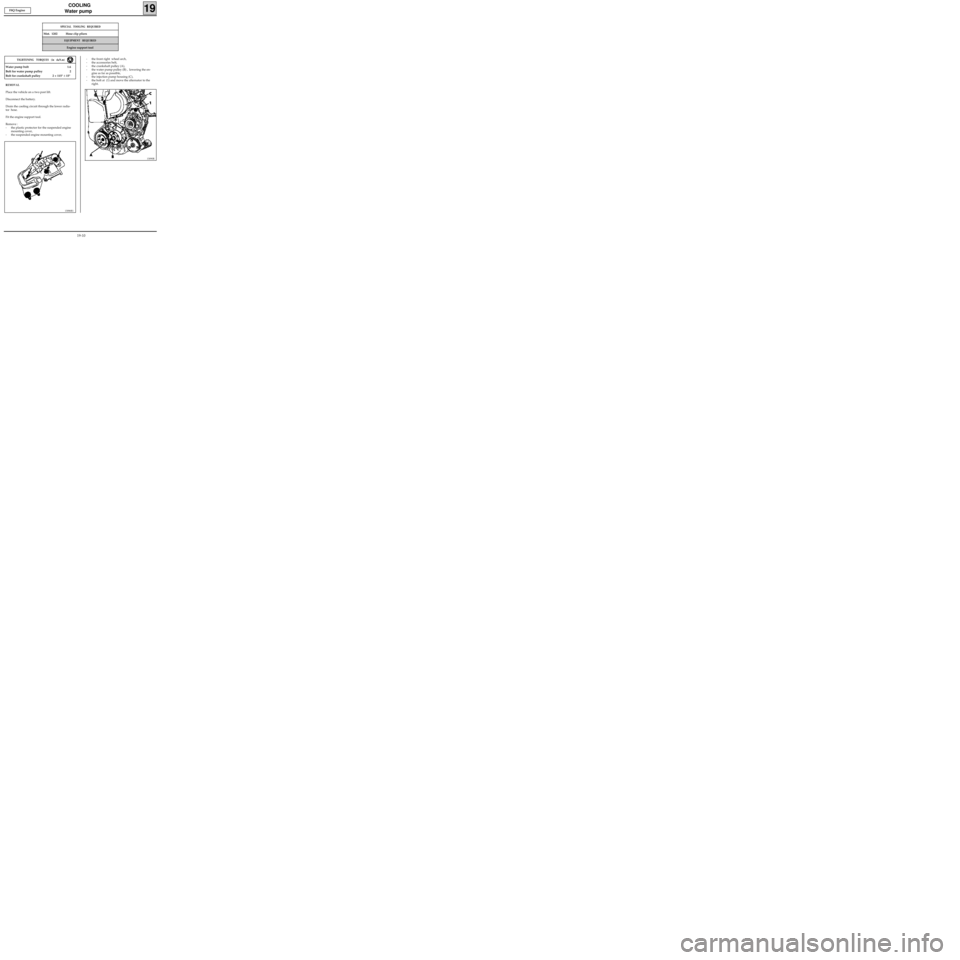
Remove :
- the plastic protector for the suspended engine
mounting cover,
- the suspended engine mounting cover,
EQUIPMENT REQUIRED
Engine support tool
- the front right wheel arch,
- the accessories belt,
- the crankshaft pulley (A),
- the water pump pulley (B) , lowering the en-
gine as far as possible,
- the injection pump housing (C),
- the bolt at (1) and move the alternator to the
right.
13086R1
19-10
Page 192 of 208
FUEL TANK
Fuel tank
19
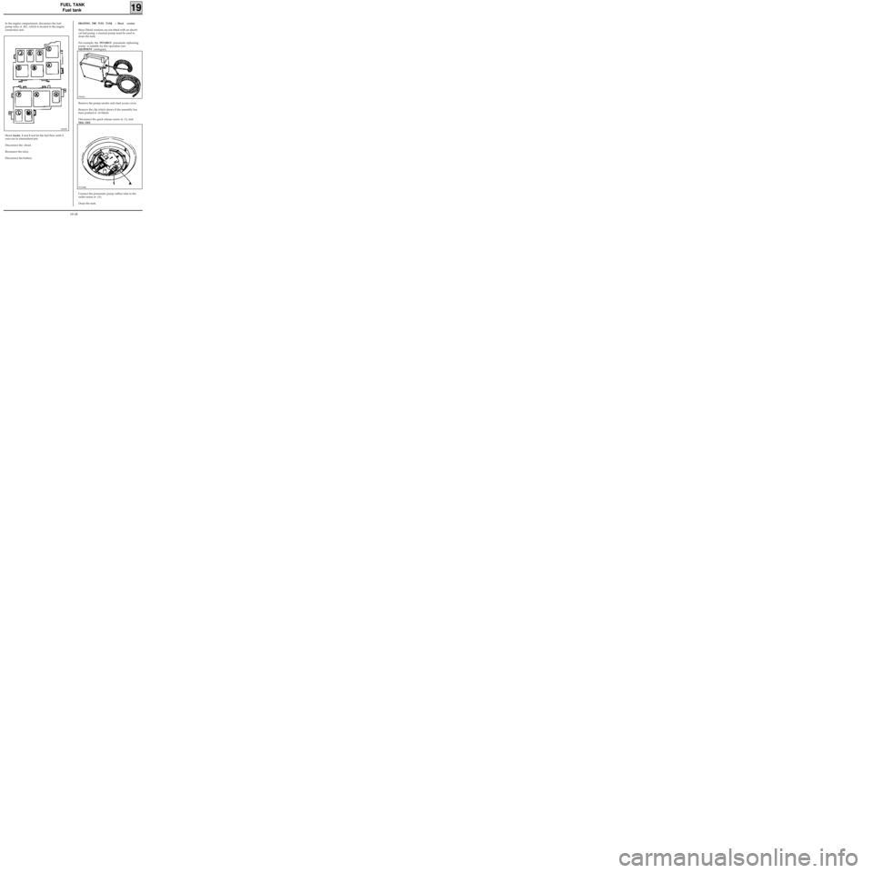
In the engine compartment, disconnect the fuel
pump relay at (K) , which is located in the engine
connection unit.
12839S
DRAINING THE FUEL TANK ( Diesel version)
Since Diesel versions are not fitted with an electri-
cal fuel pump, a manual pump must be used to
drain the tank.
For example, the
INTAIRCO pneumatic siphoning
pump is suitable for this operation (see
EQUIPMENT catalogue),
Shunt tracks 3 and 5 and let the fuel flow until it
runs out in intermittent jets.
Disconnect the shunt.
Reconnect the relay.
Disconnect the battery.Remove the pump-sender unit steel access cover.
Remove the clip which shows if the assembly has
been pushed in (if fitted).
Disconnect the quick release union at (1), tool
Mot. 1265.
99641S
97163R2
Connect the pneumatic pump rubber tube to the
outlet union at (A).
Drain the tank.
19-18
Page 193 of 208
TANK
Fuel Tank
19
REMOVAL OF THE TANK (petrol or diesel ver-
sions)
Disconnect the battery.
Place the vehicle on a two post lift.
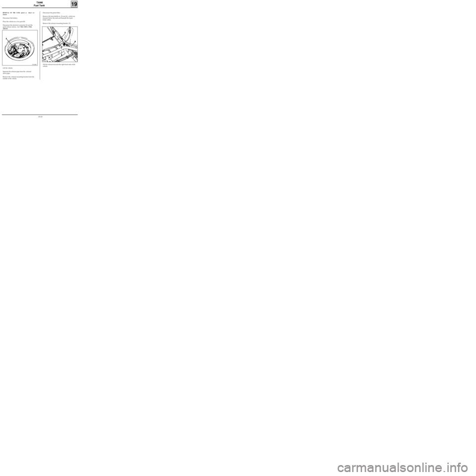
Disconnect the electrical connector (2) and the
quick release unions, tool Mot. 1265 or Mot.
1265-01.
97163R4
Disconnect the petrol filter.
Remove the heat shields at (3) and (4) , which are
situated below the tank and beneath the hand-
brake cables.
Remove the exhaust mounting bracket (5).
Lift the vehicle.
Separate the exhaust pipe from the exhaust
down pipe.
Remove the exhaust mounting bracket from the
middle of the vehicle.
12866R
Tilt the exhaust towards the right hand side of the
vehicle.
19-19
Page 204 of 208
Mot. 1264 Wrench for removing
Mot. 1264-01 pump-sender unit assembly nut
Mot. 1265 Pliers for removing
Mot. 1265-01 quick release unions
FUEL TANK
Pump- sender unit
19
SPECIAL TOOLING REQUIRED
IMPORTANT :
During all operations on the fuel tank or on the
fuel supply circuit , it is vital :
- to refrain from smoking and handling incan-
descent objects in the vicinity of the working
area,
- to avoid fuel projections, due to the residual
pressure present in the pipes during removal .
REMOVAL
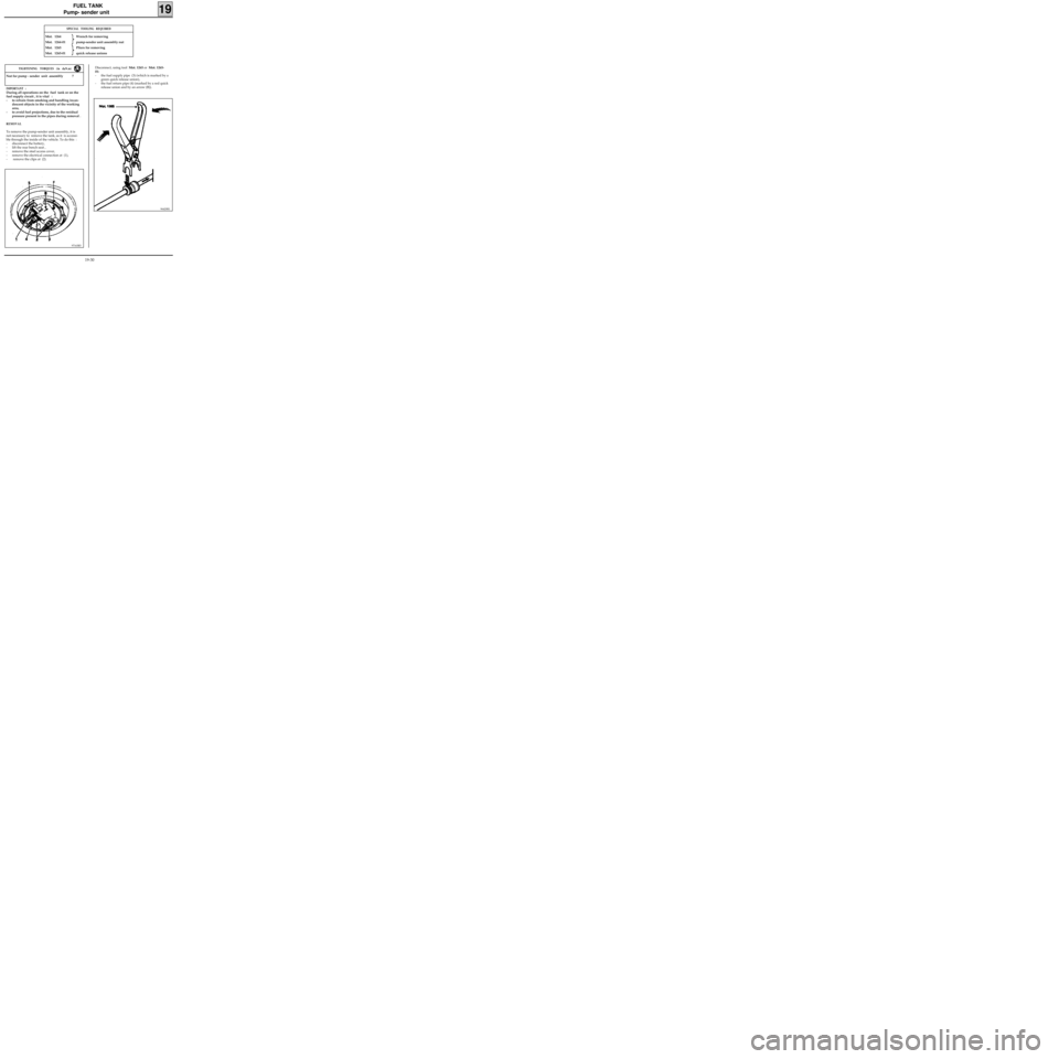
To remove the pump-sender unit assembly, it is
not necessary to remove the tank, as it is accessi-
ble through the inside of the vehicle. To do this :
- disconnect the battery,
- lift the rear bench seat ,
- remove the steel access cover,
- remove the electrical connection at (1),
- remove the clips at (2).
97163R5
Nut for pump - sender unit assembly 7
TIGHTENING TORQUES (in daN.m)Disconnect, using tool Mot. 1265 or Mot. 1265-
01:
- the fuel supply pipe (3) (which is marked by a
green quick release union),
- the fuel return pipe (4) (marked by a red quick
release union and by an arrow (B)).
96420R1
19-30