fuel RENAULT KANGOO 1997 KC / 1.G Engine And Peripherals Service Manual
[x] Cancel search | Manufacturer: RENAULT, Model Year: 1997, Model line: KANGOO, Model: RENAULT KANGOO 1997 KC / 1.GPages: 208
Page 88 of 208
FUEL SUPPLY
Fuel pressure
13
CHECKING THE FUEL PRESSURE
SPECIAL TOOLING REQUIRED
Mot. 1311-01 Fuel pressure test kit (with a pressure
gauge 0; + 10 bar tool kit)
Mot. 1311-05 Junction tool (for union K)
Mot. 1311-06 Tool for removing fuel supply unions
IMPORTANT : during the opening of the fuel cir-
cuit , be sure to use a cloth to avoid possible pro-
jections of fuel due to the residual pressure.
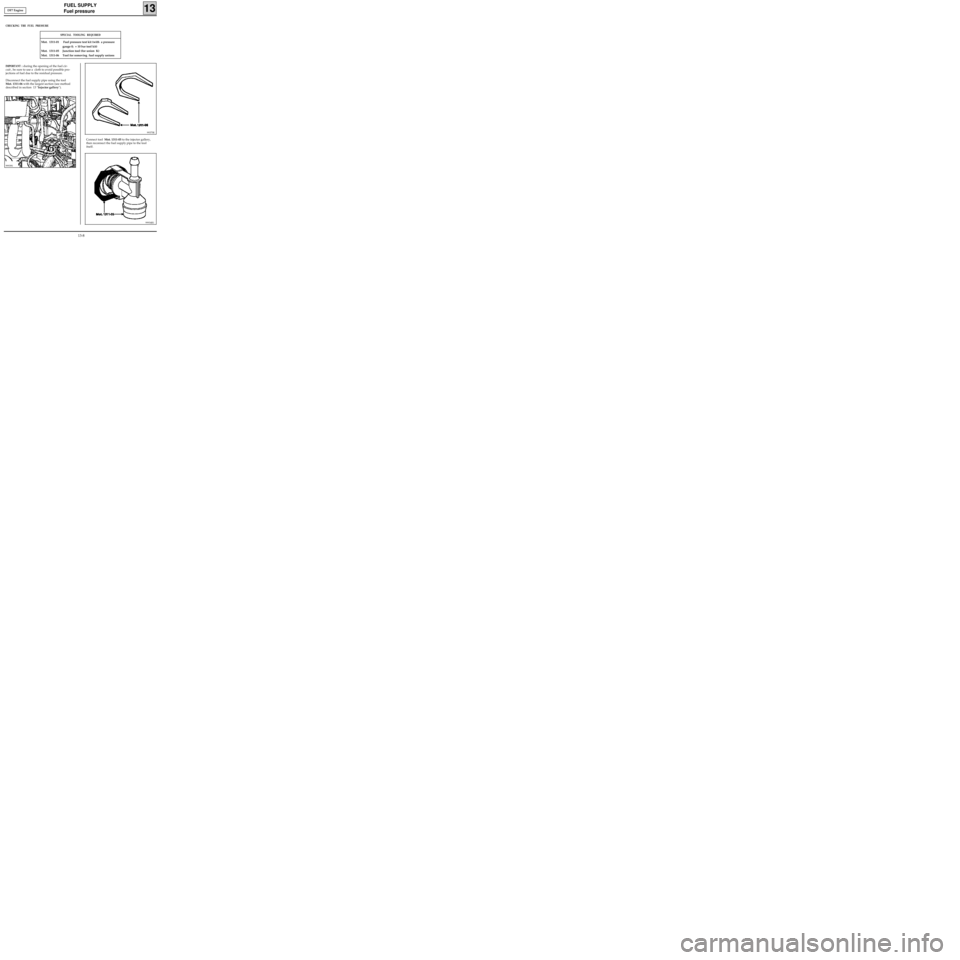
Disconnect the fuel supply pipe using the tool
Mot. 1311-06 with the largest section (see method
described in section 13 "Injector gallery").
Connect tool Mot. 1311-05 to the injector gallery,
then reconnect the fuel supply pipe to the tool
itself.
99375R
99934R1
99939S
DF7 Engine
13-8
Page 89 of 208
FUEL SUPPLY
Fuel pressure
13
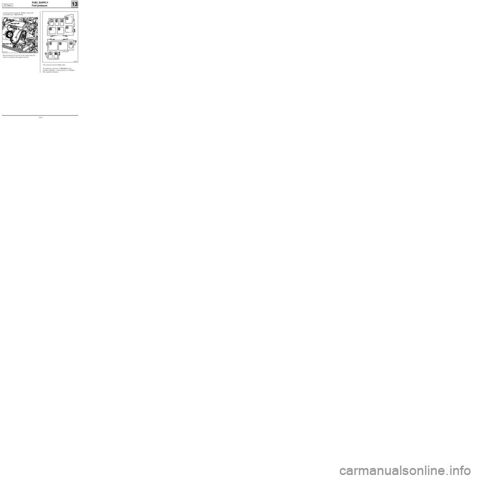
Connect pressure gauge 0 ; 10 bars along with
the flexible hose, Mot. 1311-01.
Shunt terminals (3) and (5) on the pump relay (K) ,
which is situated in the engine fuse box.
99938-1R
12839S
The pressure must be 3 bars ± 0,2.
By applying a pressure of 500 mbars to the
pressure regulator, a fuel pressure of 2.5 bars ±
0.2 should be obtained. DF7 Engine
13-9
Page 90 of 208
FUEL SUPPLY
Fuel pressure
13
CHECKING THE FUEL PRESSURE
SPECIAL TOOLING REQUIRED
Mot. 1311-01 Fuel pressure test kit (with a pressure
gauge 0; + 10 bar tool kit)
Mot. 1311-05 Junction tool (for union J)
IMPORTANT : during the opening of the fuel cir-
cuit , be sure to use a cloth to avoid possible pro-
jections of fuel due to the residual pressure.
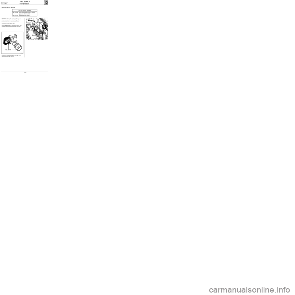
Disconnect the fuel supply pipe.
Fit tool Mot. 1311-04 on the injector gallery, then
reconnect the fuel supply pipe to the tool itself.
13244-1R
EF7 Engine
Connect the pressure gauge 0; + 10 bars with
the flexible pipe Mot. 1311-01.
99376R
13-10
Page 91 of 208
FUEL SUPPLY
Fuel pressure
13E7J Engine
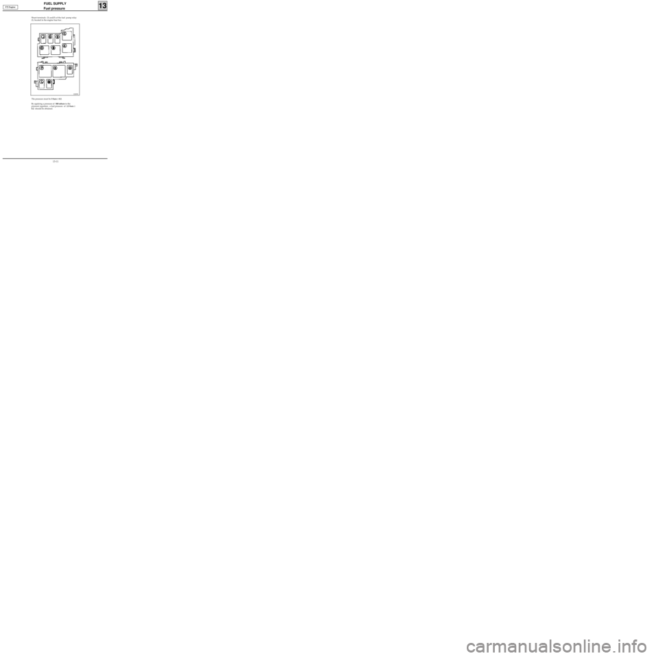
Shunt terminals (3) and(5) of the fuel pump relay
(L) located in the engine fuse box .
12839S
The pressure must be 3 bars ± 0.2.
By applying a pressure of 500 mbars to the
pressure regulator, a fuel pressure of 2.5 bars ±
0.2 should be obtained.
13-11
Page 92 of 208
FUEL SUPPLY
Antipercolation device
13
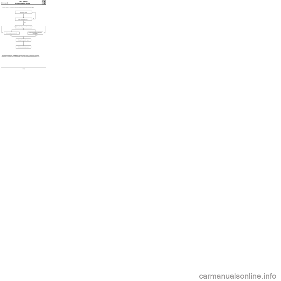
When the ignition is switched off, the coolant temperature monitoring mode begins.
E7J Engine
Monitoring mode
Water temperature≥ 101°C
Coolant temperature ≤ 96°C Cooling fan assembly control time
≥ 10 minutes
Cooling fan assembly stops
Exit from monitoring mode
The monitoring mode is left 2 minutes after switching off the ignition in cases where the coolant
temperature is not greater than or equal to 101°C or once the coolant temperature falls below 92°C.
no
yes
nono
yes yes
High speed cooling fan assembly command
13-12
Page 96 of 208
DIESEL EQUIPMENT
Location of components
13
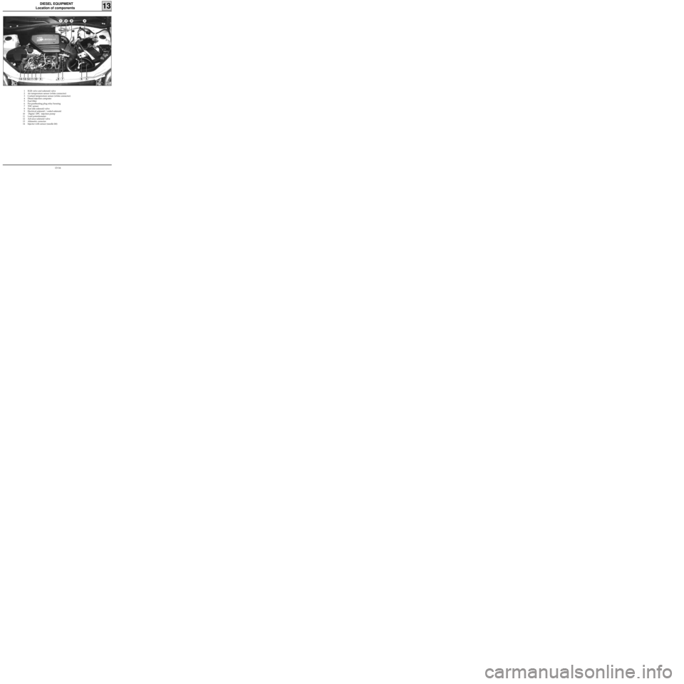
1 EGR valve and solenoid valve
2 Air temperature sensor (white connector)
3 Coolant temperature sensor (white connector)
4 Diesel injection computer
5 Fuel filter
6 Pre-postheating plug relay housing
7 TDC sensor
8 Fast idle solenoid valve
9 Electrical solenoid / coded solenoid
10 Digital DPC injection pump
11 Load potentiometer
12 Advance solenoid valve
13 Altimetric corrector
14 Injector with sensor (needle lift)
12874
13-16
Page 97 of 208
DIESEL EQUIPMENT
Location of components
13
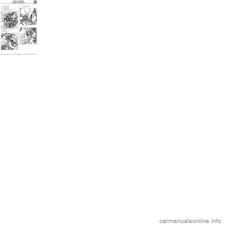
12Advance solenoid valve
14Injector with sensor
13Altimetric corrector
11Load potentiometer
9Electrical solenoid / coded solenoid valve
8Idle speed solenoid valve
12869-1R
3Coolant temperature sensor
2Air temperature sensor
6Pre-postheating plug relay housing
5Fuel filter
16Inertia switch
4Injection computer
13083R
12872R
19 EGR solenoid valve
12871R
13-17
Page 107 of 208
DIESEL EQUIPMENT
Coded solenoid valve
13
On this type of vehicle, the replacement of the
solenoid valve and of the coded electronic unit (A)
requires the removal of the injection pump from
the engine.
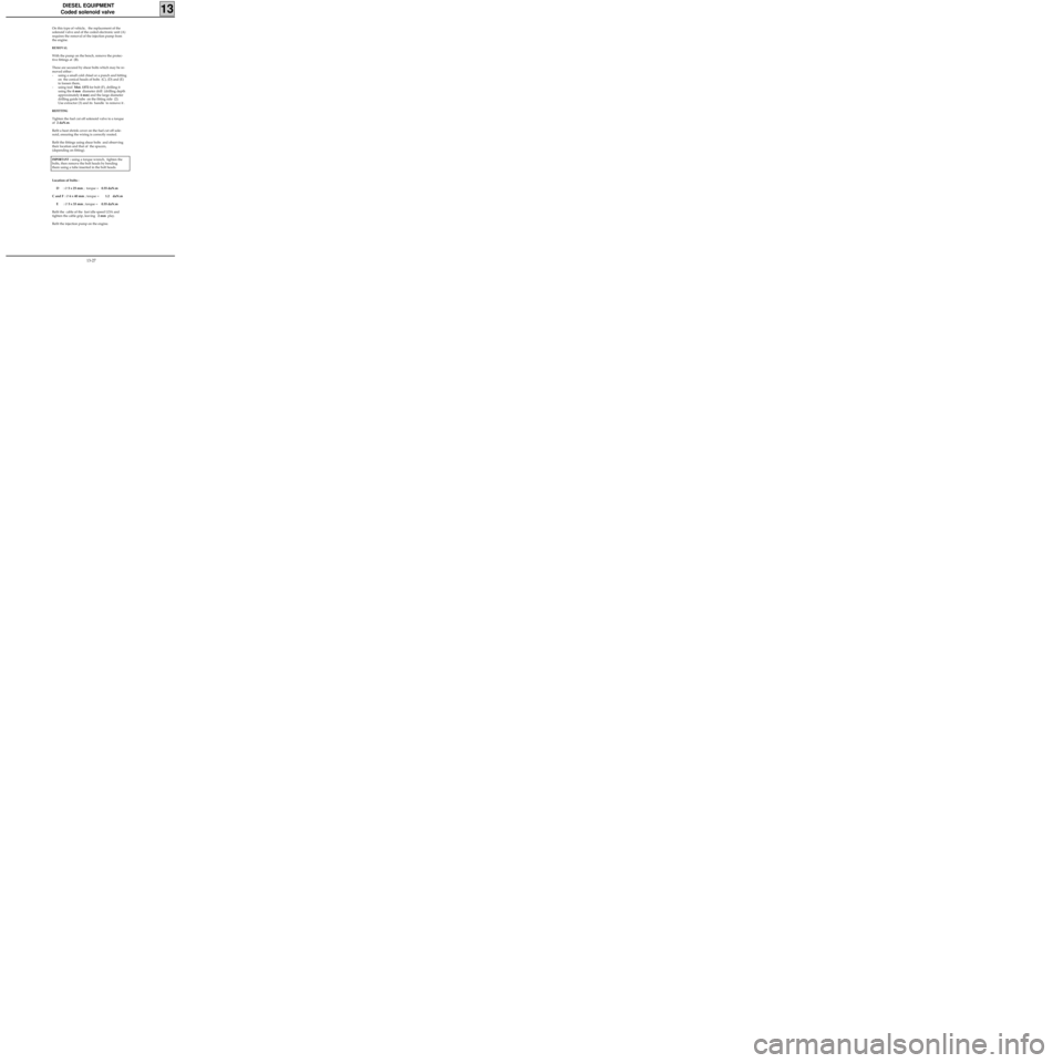
REMOVAL
With the pump on the bench, remove the protec-
tive fittings at (B).
These are secured by shear bolts which may be re-
moved either :
- using a small cold chisel or a punch and hitting
on the conical heads of bolts (C), (D) and (E)
to loosen them,
- using tool Mot. 1372 for bolt (F), drilling it
using the 4 mm diameter drill (drilling depth
approximately 4 mm) and the large diameter
drilling guide tube on the fitting side (2).
Use extractor (3) and its handle to remove it .
REFITTING
Tighten the fuel cut off solenoid valve to a torque
of 2 daN.m.
Refit a heat shrink cover on the fuel cut off sole-
noid, ensuring the wiring is correctly routed.
Refit the fittings using shear bolts and observing
their location and that of the spacers,
(depending on fitting).
IMPORTANT : using a torque wrench, tighten the
bolts, then remove the bolt heads by bending
them using a tube inserted in the bolt heads.
Location of bolts :
D :
∅ 5 x 25 mm ; torque =0.55 daN.m
C and F :
∅ 6 x 40 mm ; torque =1.2 daN.m
E :
∅ 5 x 33 mm ; torque =0.55 daN.m
Refit the cable of the fast idle speed LDA and
tighten the cable grip, leaving 2 mm play.
Refit the injection pump on the engine.
13-27
Page 120 of 208
DIESEL EQUIPMENT
Pump
13
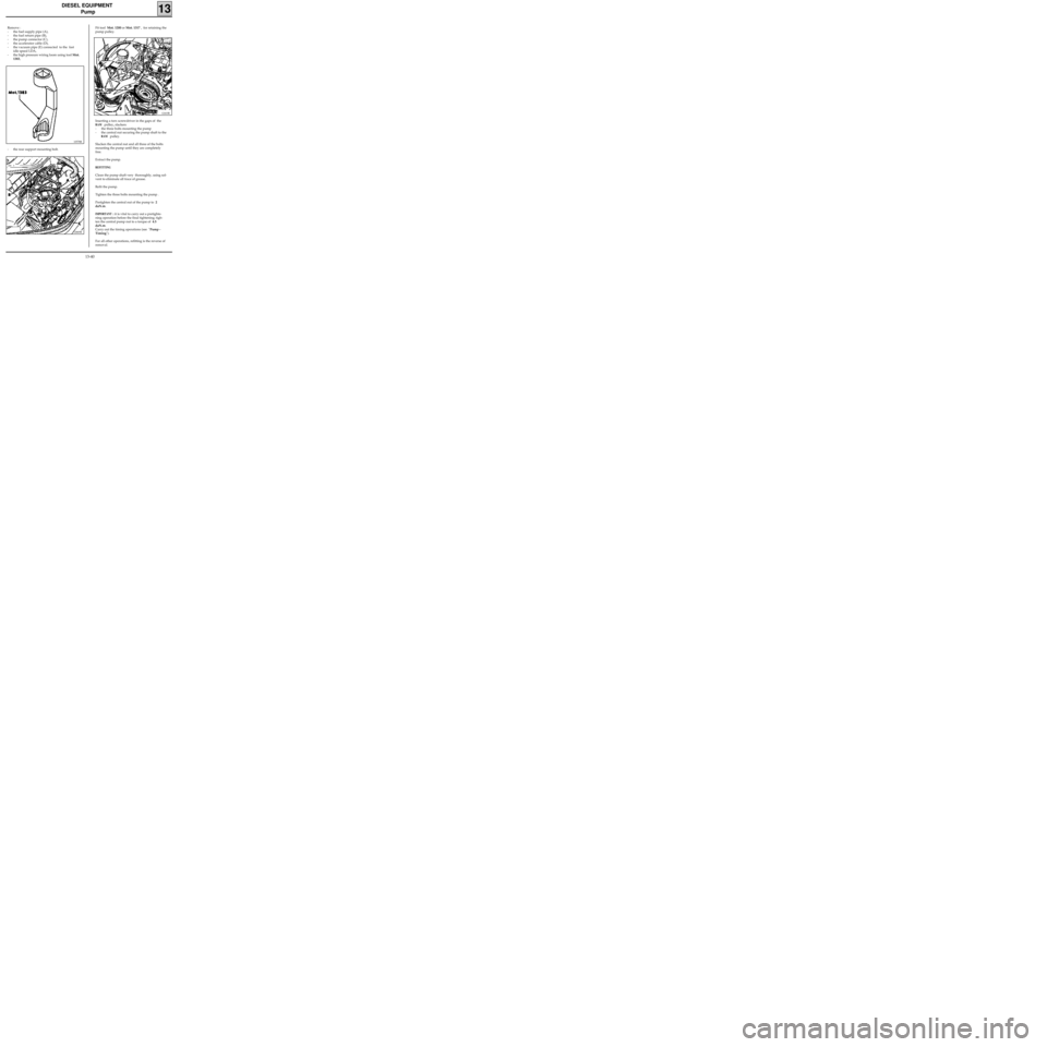
Remove :
- the fuel supply pipe (A),
- the fuel return pipe (B),
- the pump connector (C),
- the accelerator cable (D),
- the vacuum pipe (E) connected to the fast
idle speed LDA,
- the high pressure wiring loom using tool Mot.
1383,
10578R
- the rear support mounting bolt.
12869R
Fit tool Mot. 1200 or Mot. 1317 , for retaining the
pump pulley.
12410R
Inserting a torx screwdriver in the gaps of the
RAM pulley, slacken:
- the three bolts mounting the pump
- the central nut securing the pump shaft to the
RAM pulley.
Slacken the central nut and all three of the bolts
mounting the pump until they are completely
free.
Extract the pump.
REFITTING
Clean the pump shaft very thoroughly, using sol-
vent to eliminate all trace of grease.
Refit the pump.
Tighten the three bolts mounting the pump .
Pretighten the central nut of the pump to 2
daN.m.
IMPORTANT : it is vital to carry out a pretighte-
ning operation before the final tightening; tigh-
ten the central pump nut to a torque of 4.5
daN.m.
Carry out the timing operations (see "Pump -
Timing").
For all other operations, refitting is the reverse of
removal.
13-40
Page 128 of 208
ANTIPOLLUTION
Fuel vapour rebreathing
14
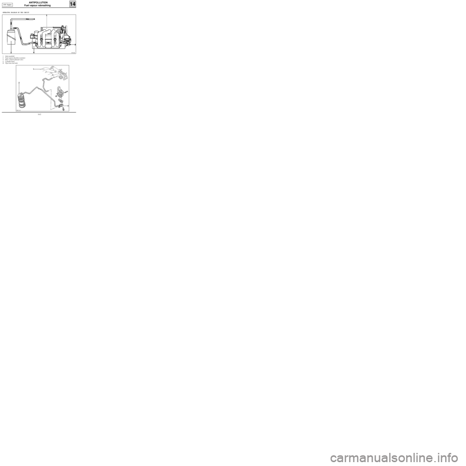
OPERATING DIAGRAM OF THE CIRCUIT
1 Inlet manifold
2 Fuel vapour absorber (canister)
3 RCO control solenoid valve
4 Cylinder head
R Pipe from fuel tank
99933R
PRC14.1
D7F Engine
14-2