fuel RENAULT KANGOO 1997 KC / 1.G Engine And Peripherals User Guide
[x] Cancel search | Manufacturer: RENAULT, Model Year: 1997, Model line: KANGOO, Model: RENAULT KANGOO 1997 KC / 1.GPages: 208
Page 24 of 208

ENGINE AND ENGINE PERIPHERALS
Engine and transmission assembly
10
12988R
- the exhaust heat shield and the gear control
on the lever and gearbox sides,
- the exhaust downpipe,
- the earth strap on the gearbox,
- the front bumper,
- the air intake pipe of the air filter,
- the fuel supply and return unions (A) and (B),
- the connectors (2), (3), (4) and (5).
Unclip the fuel pipes from the air filter unit and
the timing cover and unclip the diesel filter from
its support and move the assembly to one side.
13083-1R
F8Q engine
10-20
Page 46 of 208
12mm torx socket
Angular tightening wrench
TOP AND FRONT OF ENGINE
Cylinder head gasket
11
SPECIAL TOOLING REQUIRED
Mot. 591-04 Angle wrench for tightening
cylinder head and index
Mot. 1202 Hose clip pliers
Mot. 1273 Tool for checking belt tension
Mot. 1379 Tool for securing engine to
subframe
EQUIPMENT REQUIRED
TIGHTENING TORQUES (in daN.m)
Crankshaft output mounting bolt 2 + 90°
Mounting bolt for front right suspended
engine mounting on engine 6.2
Mounting bolt for front right suspended
engine mounting on vehicle body 6.2
Timing belt tension wheel nut 5
Wheel bolts 9
REMOVAL
Put the vehicle on a 2 post lift.
Remove the bonnet, and the right hand wheel .
Disconnect the battery.
Drain the cooling circuit.
Fit the engine support tool, Mot. 1379.Remove:
- the timing belt (see method described in
section 11 "Timing belt"),
- the dipstick,
- the brake servo pipe,
- the air filter,
- the accelerator cable,
- the fuel supply and return pipes level with the
timing belt cover on the cylinder head
D7F Engine
11-11
Page 47 of 208
TOP AND FRONT OF ENGINE
Cylinder head gasket
11
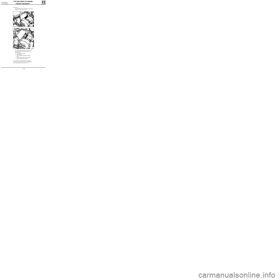
- the canister pipe along with the fuel vapour
rebreathing hoses on the solenoid valve,
- the connectors :
• of the ignition module,
• of the injectors,
• of the idle speed regulation stepping
motor,
• of the throttle position potentiometer,
• of the air temperature sensor.
Extract the hose connecting the water pump to
the heater matrix, and the electrical wiring loom
from the heat shield on the rocker cover.
99940R
Disconnect :
- the spark plug leads using tool (3) which is in-
tegrated to the plastic cover (4),
99894R1
D7F Engine
11-12
Page 52 of 208
TOP AND FRONT OF ENGINE
Cylinder head gasket
11
SPECIAL TOOLING REQUIRED
DEPOSE
Place the vehicle on a 2 post lift .
Disconnect the battery.
Remove :
- the bonnet ,
- the timing belt (see method described in sec-
tion 11, "Timing belt ").
Drain the cooling circuit through the lower radia-
tor hose.
Fit tool Mot. 1159 between the engine subframe
and the cylinder block.
99024R2
EQUIPMENT REQUIRED
Engine support tool
55mm torx socket
Mot. 588 Retaining bracket
Mot. 591-02 Index
Mot. 591-04 Angle tightening angular
wrench
Mot. 1159 Tool for retaining engine on
subframe
Mot. 1202 Hose clip pliers
Mot. 1273 Tool for checking belt tension
Mot. 1311-06 Tool for removing fuel pipe
Tension wheel nut 5
Crankshaft pulley bolt 2 + 68° ± 6°
Bolt for suspended engine mounting 6.2
cover
Nut for suspended engine mounting cover 4.4
Wheel bolts 9
TIGHTENING TORQUES (in daN.m or /and °)
E7J Engine
11-17
Page 54 of 208
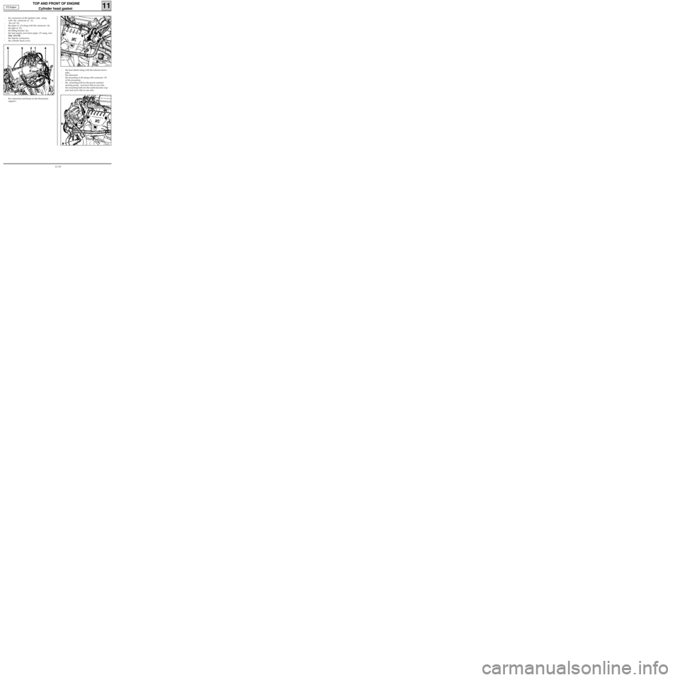
- the heat shield along with the exhaust down-
pipe,
- the alternator,
- the mounting at (8) along with connector (9)
of the pressostat,
- the mounting bolt for the power assisted
steering pump and move this to one side ,
- the mounting bolts for the multi-function sup-
port and move this to one side,
TOP AND FRONT OF ENGINE
Cylinder head gasket
11
13365S
13364R1
13360R
- the connectors and hoses on the thermostat
support , - the connectors of the ignition coils, along
with the connector at (1),
- the coil (2),
- the pipes at (3) along with the connector (4),
- the pipe at (5),
- the lifting bracket (6),
- the fuel supply and return pipes (7) using tool
Mot. 1311-06,
- the injector connectors,
- the cylinder head cover , E7J Engine
11-19
Page 58 of 208
TOP AND FRONT OF ENGINE
Cylinder head gasket
11
SPECIAL TOOLING REQUIRED
REMOVAL
Place the vehicle on a two post lift .
Disconnect the battery.
Remove :
- the bonnet,
- the timing belt (see method described in
section 11 "Timing belt").
Drain the cooling circuit via the lower radiator
hose.
EQUIPMENT REQUIRED
Engine support tool
55mm torx socket
Mot. 251-01 Dial gauge support tool
Mot. 252-01 Plate for measuring piston
protrusion
Mot. 591-02 Index
Mot. 591-04 Angular tightening wrench
Mot. 1054
TDC pin
Mot. 1159 Tool for mounting engine on
subframe
Mot. 1202 Hose clip pliers
Mot. 1273 Tool for checking belt tension
Mot. 1311-06 Tool for removing fuel pipe
Tension wheel nut 5
Crankshaft pulley bolt 2 + 115° ± 15°
Bolt for suspended engine mounting cover 6.2
Nut for suspended engine mounting cover 4.4
Wheel bolts 9
TIGHTENING TORQUES (in daN.m or/and°)
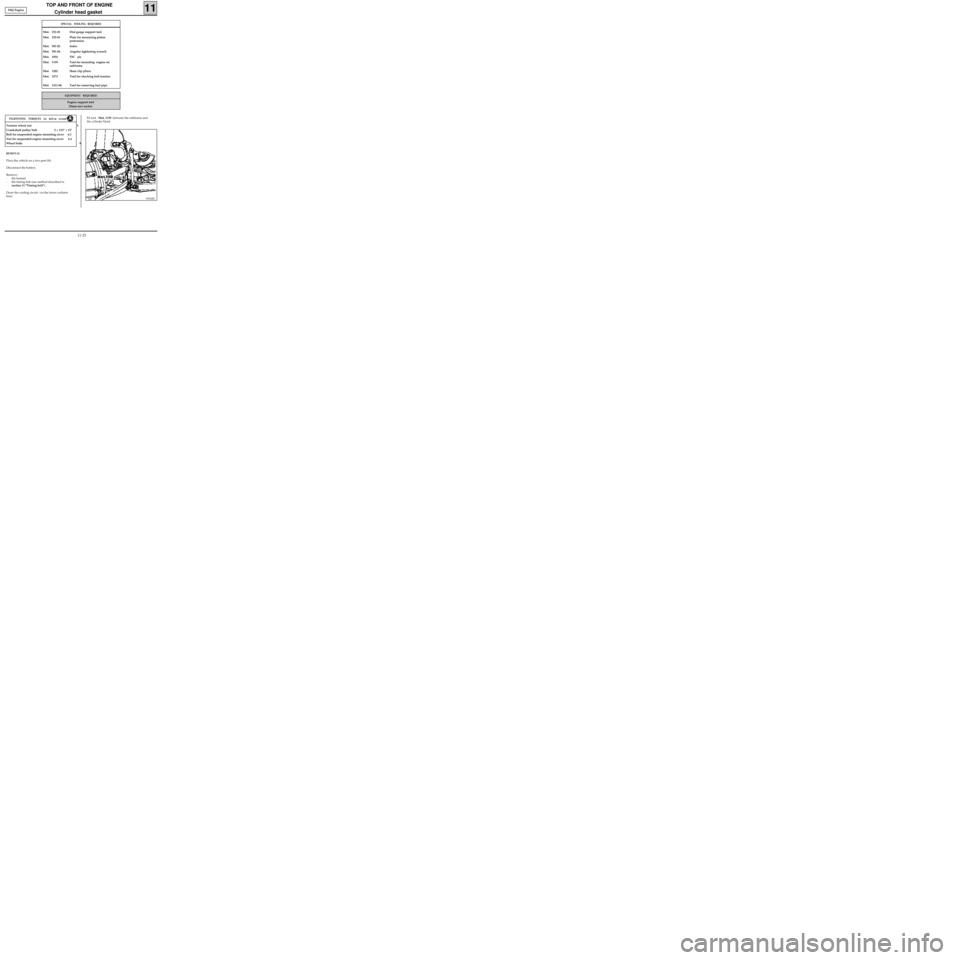
99024R2
Fit tool Mot. 1159 between the subframe and
the cylinder block. F8Q Engine
11-23
Page 59 of 208
TOP AND FRONT OF ENGINE
Cylinder head gasket
11
Remove :
- the exhaust downpipe,
- the hoses and connectors of the cylinder head
coolant pipe housing outlet,
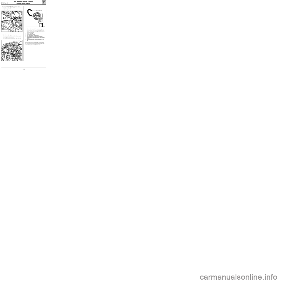
- the connection at (1) using tool Mot. 1311-06,
13097R
99461R
- the air filter assembly by disconnecting the
EGR solenoid valve and the air temperature
sensor (unclip the fuel supply pipes from the
air filter housing),
- the air inlet pipe
- the accelerator cable
- the feeds for the heater plugs ,
- the connector of the injector with sensor,
along with the fast idle solenoid valve connec-
tor (5),
- the fuel supply and return unions at (A) and
(B).
Disconnect connector (6) from the diesel fuel fil-
ter, remove it from its support and move the die-
sel fuel filter pipe assembly to one side. Place bracket Mot. 1159 at the mounting of the
coolant pipe on the cylinder block, then remove
the engine support tool.
99310R
F8Q Engine
11-24
Page 61 of 208
TOP AND FRONT OF ENGINE
Cylinder head gasket
11
11733R
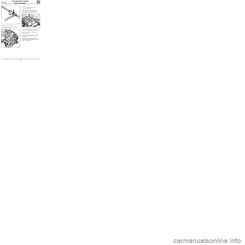
Remove the fuel pipe support (7).
Slacken the mounting bolts for the lower timing
cover, without removing them.
99173-1R
13093R
Remove :
- the accessories belt tensioning system,
- the cylinder head bolts.
Release the cylinder head by setting aside the
lower part of the lower camshaft housing,
without causing the cylinder head to pivot, since
this is centred by the two dowels at ( C ).
Using a syringe, extract any oil which may have
entered the cylinder head mounting holes .
This is necessary in order to obtain the correct
tightening of the bolts.
Protect the oil outlet duct in order to prevent any
foreign bodies from entering the oilways in the
cylinder head.
Failure to take this advice could lead to the
blocking of the oilways, resulting in a rapid dete-
rioration of the camshaft. F8Q Engine
11-26
Page 66 of 208
FUEL MIXTURE
Specifications
12
Vehicle GearboxEngine
Type SuffixBore
(mm)Stroke
(mm)Capacity
(cm
3)RatioCatalytic
converterDepollut-
ion
standard
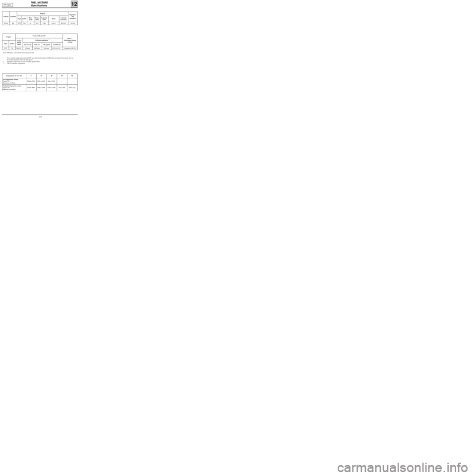
XC0A JB1 D7F 710 69 76.8 1149 9.65/1 C61 EU 96
Temperature in °C (± 1°) 0 20 40 80 90
Air temperature sensor
Type CTN
Resistance in Ohms5000 to 7000 1700 to 3300 800 to 1550 - -
Coolant temperature sensor
Type CTN
Resistance in Ohms6700 to 8000 2600 to 3000 1100 to 1300 270 to 300 200 to 215
Engine
Type SuffixTests at idle speed*
Engine
speed
[rpm]Pollutant emission **
CO (%) (1) CO
2 (%) HC (ppm) Lambda (λ)Fuel***
[minimum octane
rating]
D7F 710 740±50 0.5 max 14.5 min 100 max 0.97<λ<1.03 Unleaded (OR 95)
(1) at 2500 rpm, CO must be a maximum of 0.3
* For a coolant temperature above 80°C and after stable speed of 2500 rpm, for about 30 seconds. Test to
be carried out after return to idle speed.
** For legal values refer to your country specification.
*** OR 91 unleaded compatible.D7F engine
12-1
Page 67 of 208
FUEL MIXTURE
Specifications
12
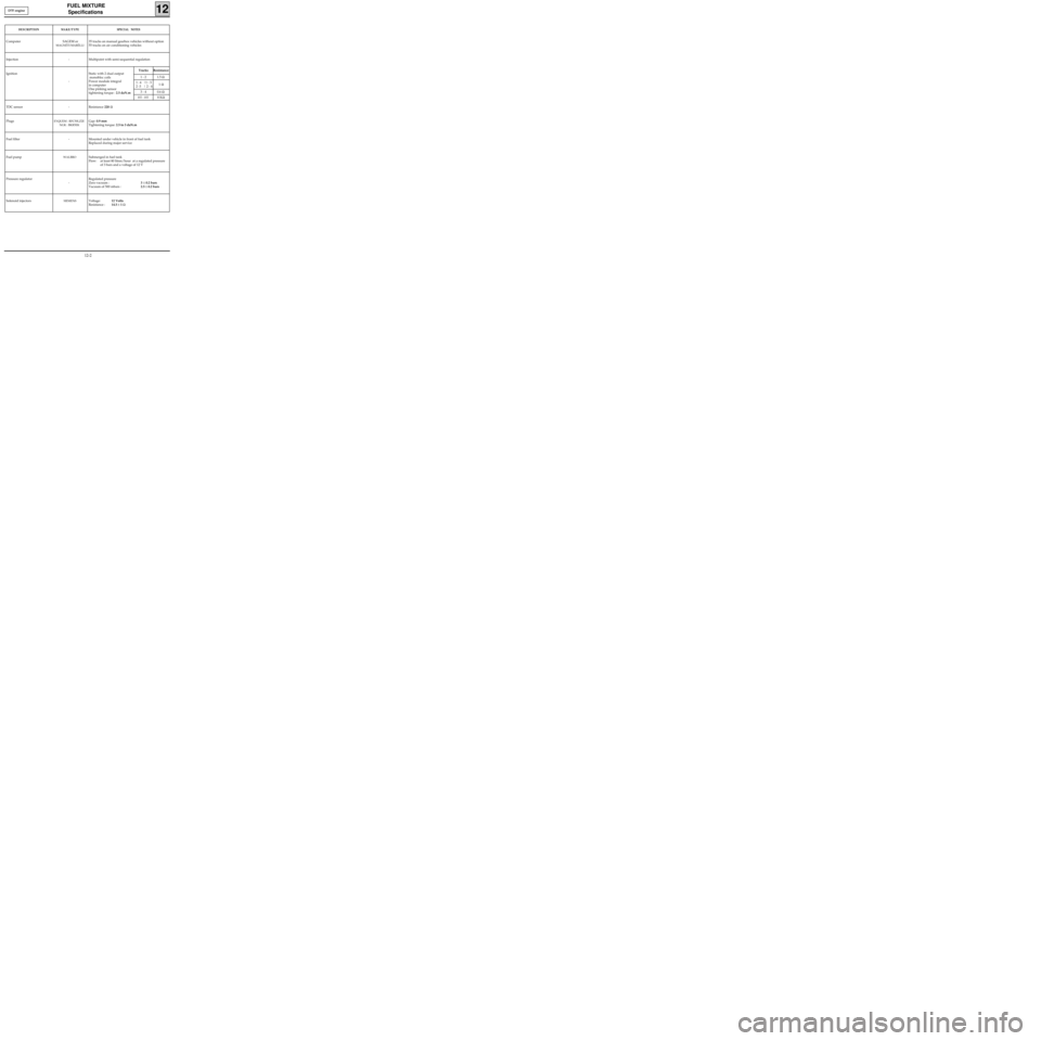
DESCRIPTIONMAKE/TYPESPECIAL NOTES
Computer SAGEM or
MAGNÉTI MARÉLLI
35 tracks on manual gearbox vehicles without option
55 tracks on air conditioning vehicles
Injection - Multipoint with semi-sequential regulation
Ignition
-Static with 2 dual output
monobloc coils
Power module integral
in computer
One pinking sensor
tightening torque : 2.5 daN.m
TDC sensor - Resistance 220 Ω
Plugs
EYQUEM : RFC50LZ2E
NGK : BKR5EKGap: 0.9 mm
Tightening torque: 2.5 to 3 daN.m
Fuel filter - Mounted under vehicle in front of fuel tank
Replaced during major service
Fuel pump
WALBROSubmerged in fuel tank
Flow: at least 80 litres/hour at a regulated pressure
of 3 bars and a voltage of 12 V
Pressure regulator
-Regulated pressure
Zero vacuum :3 ± 0.2 bars
Vacuum of 500 mbars :2.5 ± 0.2 bars
Solenoid injectors
SIEMENSVoltage:12 Volts
Resistance :14.5 ± 1 Ω
Tracks Resistance
1 - 2 1.5 Ω
1
- 4 |1 - 3
2 -3 | 2 - 41 Ω
3 - 4 0.6 Ω
HT - HT8 KΩ
D7F engine
12-2