battery RENAULT KANGOO 1997 KC / 1.G Engine And Peripherals Workshop Manual
[x] Cancel search | Manufacturer: RENAULT, Model Year: 1997, Model line: KANGOO, Model: RENAULT KANGOO 1997 KC / 1.GPages: 208
Page 8 of 208
ENGINE AND ENGINE PERIPHERALS
Engine - Gearbox
10
REMOVAL
Put the vehicle on a 2 post lift.
Disconnect:
- the battery,
- the electrical connectors from the engine
connection unit and its environment.
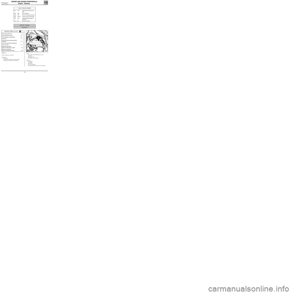
13034S
Drain:
- the cooling circuit (bottom hose of the
radiator),
- the gearbox oil,
- the engine oil if necessary.
Remove:
- the battery,
- the bonnet,
- the wheels,
- the air intake pipe,
- the expansion bottle and fix it to the engine. Brake caliper guide bolt 4
Shock absorber base bolts 18
Driveshaft gaiter mounting bolt 2.5
Wheel bolt 9
Left-hand suspended mounting bolt
on gearbox 6.2
Left-hand suspended mounting bolt
and nut on body 2.1
Right hand suspended
engine mounting bolt on engine 6.2
Right hand suspended
engine mounting bolt on body 6.2
TIGHTENING TORQUES (in daN.m)
D7F engine
SPECIAL TOOLING REQUIRED
B. Vi. 31-01 Set of three punches for roll
pins
Mot. 1202 Hose clip pliers
Mot. 1273 Tool for checking belt tension
Mot. 1311-06 Tool for removal of fuel pipe
Mot. 1379 Tool for retaining engine on
sub-frame
T. Av. 476 Ball joint extractor
EQUIPMENT REQUIRED
Load positioner
10-4
Page 13 of 208
ENGINE AND ENGINE PERIPHERALS
Engine and transmission assembly
10
REMOVAL
Put the vehicle on a 2 post lift.
Disconnect:
- the battery,
- the electrical connectors from the engine
connection unit and its environment.
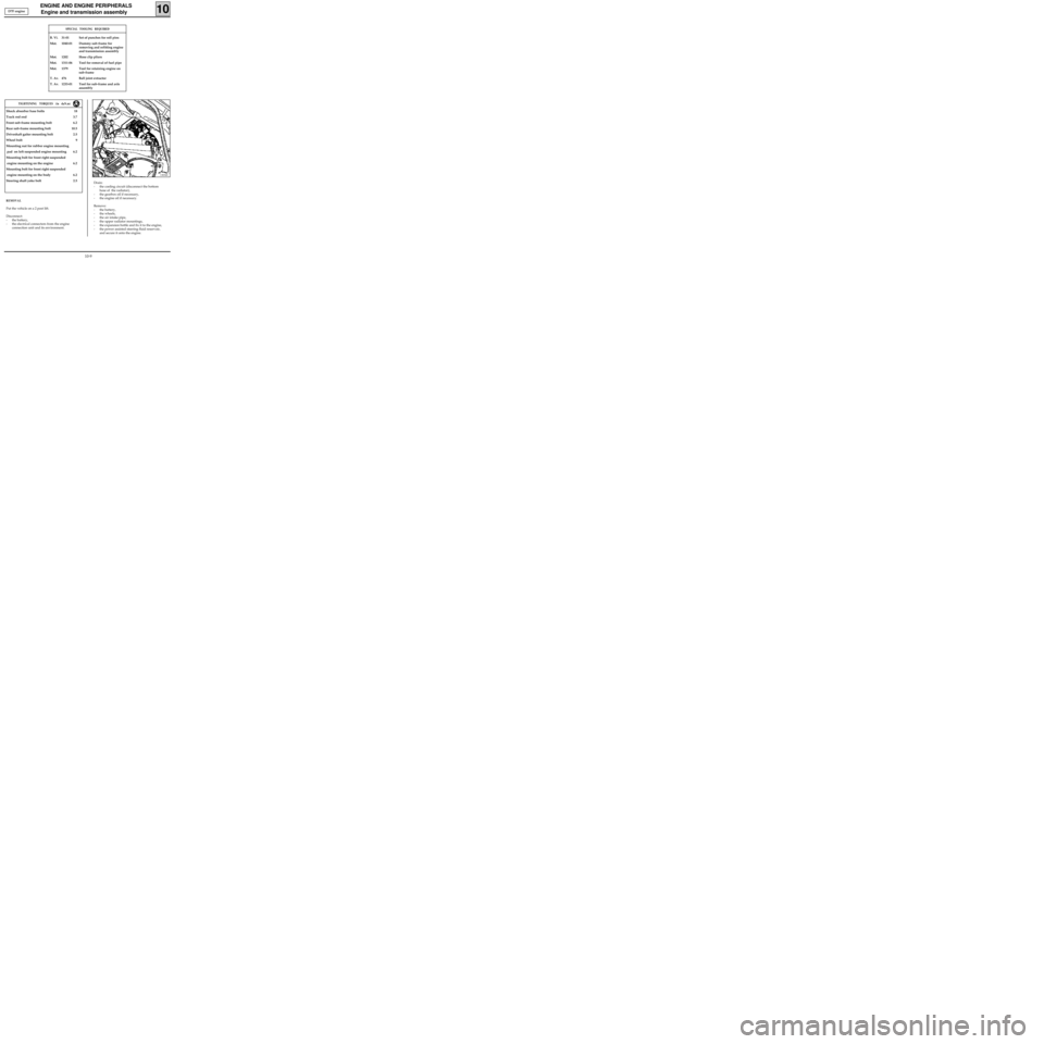
13034S
Drain:
- the cooling circuit (disconnect the bottom
hose of the radiator),
- the gearbox oil if necessary,
- the engine oil if necessary.
Remove:
- the battery,
- the wheels,
- the air intake pipe,
- the upper radiator mountings,
- the expansion bottle and fix it to the engine,
- the power assisted steering fluid reservoir,
and secure it onto the engine. Shock absorber base bolts 18
Track rod end 3.7
Front sub-frame mounting bolt 6.2
Rear sub-frame mounting bolt 10.5
Driveshaft gaiter mounting bolt 2.5
Wheel bolt 9
Mounting nut for rubber engine mounting
pad on left suspended engine mounting 6.2
Mounting bolt for front right suspended
engine mounting on the engine 6.2
Mounting bolt for front right suspended
engine mounting on the body 6.2
Steering shaft yoke bolt 2.5
TIGHTENING TORQUES (in daN.m)
D7F engine
SPECIAL TOOLING REQUIRED
B. Vi. 31-01 Set of punches for roll pins
Mot. 1040-01 Dummy sub-frame for
removing and refitting engine
and transmission assembly
Mot. 1202 Hose clip pliers
Mot. 1311-06 Tool for removal of fuel pipe
Mot. 1379 Tool for retaining engine on
sub-frame
T. Av. 476 Ball joint extractor
T. Av. 1233-01 Tool for sub-frame and axle
assembly
10-9
Page 18 of 208
ENGINE AND ENGINE PERIPHERALS
Engine and transmission assembly
10
Front sub-frame mounting bolt 6.2
Rear sub-frame mounting bolt 10.5
Mounting bolt for front right suspended
engine mounting cover on engine 6.2
Mounting nut for front right suspended
engine mounting cover 4.4
Mounting nut for rubber engine mounting pad
on front left-hand side member support 6.2
Shock absorber base bolt 18
Brake caliper mounting bolt 4
Steering shaft yoke bolt 3
Wheel bolt 9
TIGHTENING TORQUES (in daN.m)
REMOVAL
Put the vehicle on a 2 post lift.
Disconnect the battery.
Drain:
- the cooling circuit through the bottom hose
of the radiator,
- the gearbox and the engine if necessary.
Remove:
- the bonnet,
- the front wheels,
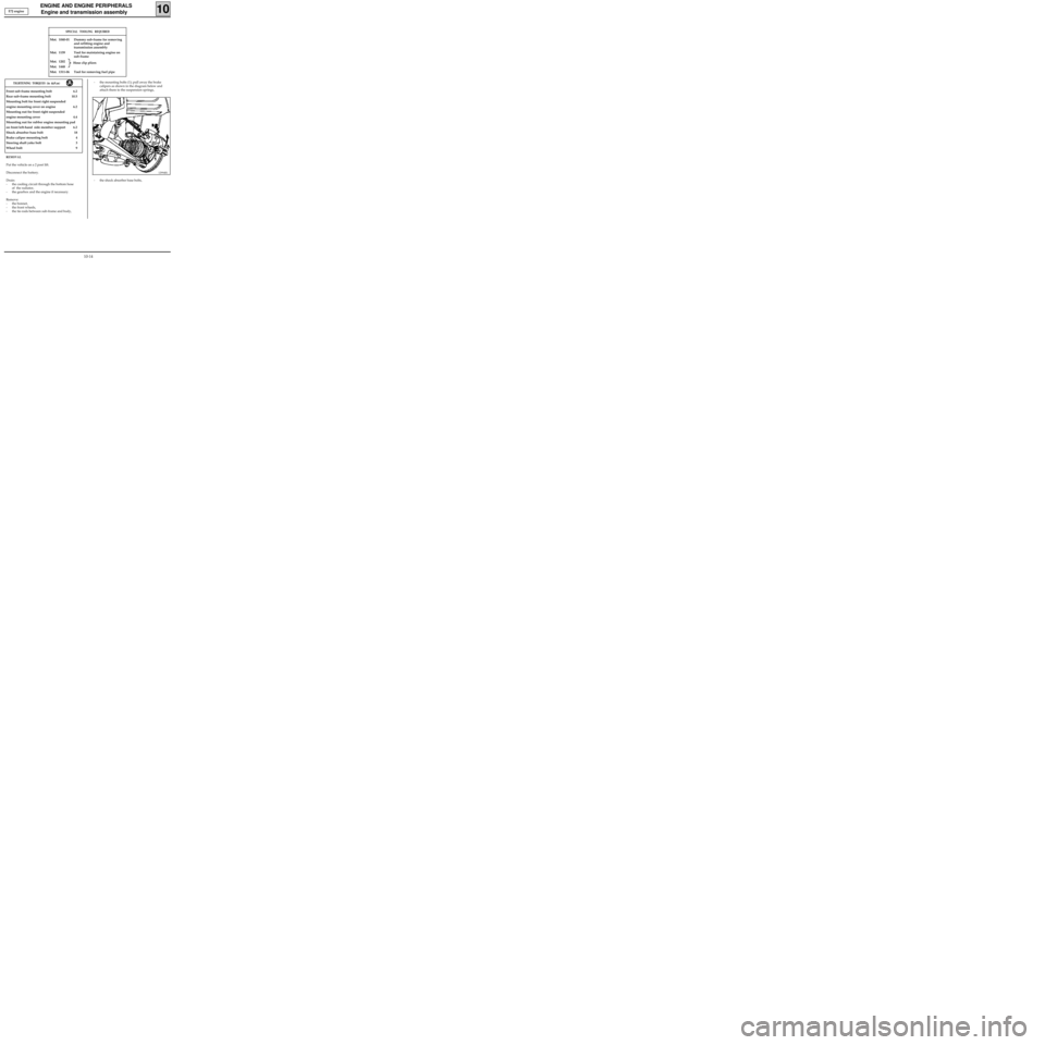
- the tie-rods between sub-frame and body,- the mounting bolts (1); pull away the brake
calipers as shown in the diagram below and
attach them to the suspension springs,
12994R1
- the shock absorber base bolts, E7J engine
SPECIAL TOOLING REQUIRED
Mot. 1040-01 Dummy sub-frame for removing
and refitting engine and
transmission assembly
Mot. 1159 Tool for maintaining engine on
sub-frame
Mot. 1202
Mot. 1448
Mot. 1311-06 Tool for removing fuel pipe
Hose clip pliers
10-14
Page 23 of 208
ENGINE AND ENGINE PERIPHERALS
Engine and transmission assembly
10
SPECIAL TOOLING REQUIRED
Mot. 1040-01 Dummy sub-frame for removing -
refitting the engine and
transmission assembly
Mot. 1159 Tool for maintaining engine on
sub-frame
Mot. 1202
Mot. 1448
Mot. 1311-06 Tool for removing fuel pipe
Front sub-frame mounting bolt 6.2
Rear sub-frame mounting bolt 10.5
Mounting bolt for front right suspended engine
mounting cover on engine 6.2
Mounting nut for front right suspended engine
mounting cover 4.4
Mounting nut for rubber engine mounting
pad on front left side member support 6.2
Shock absorber base bolt 18
Brake caliper mounting bolt 4
Steering shaft yoke bolt 3
Wheel bolt 9
TIGHTENING TORQUES (in daN.m)
REMOVAL
Put the vehicle on a 2 post lift.
Disconnect the battery.
Drain:
- the cooling circuit through the bottom hose
of the radiator,
- the gearbox and the engine if necessary.
Remove:
- the bonnet,
- the front wheels,
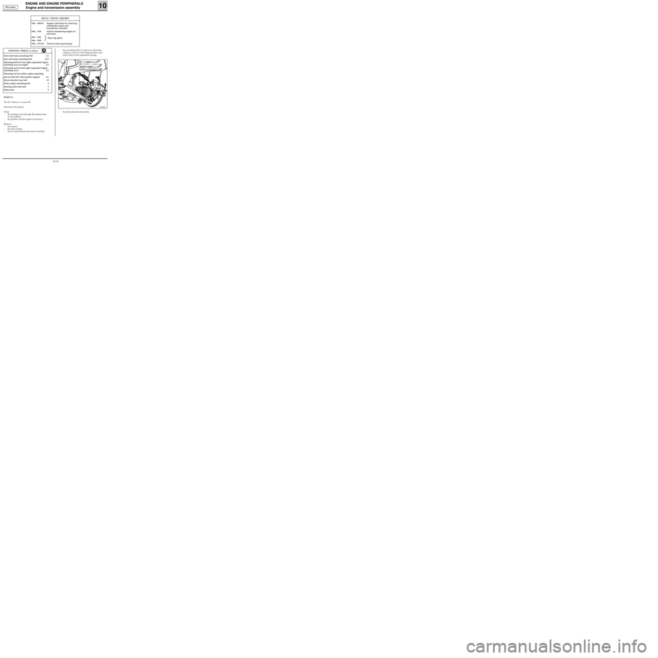
- the tie-rods between sub-frame and body,- the mounting bolts (1); pull away the brake
calipers as shown in the diagram below and
attach them to the suspension springs,
12994R1
- the shock absorber base bolts, F8Q engine
Hose clip pliers
10-19
Page 29 of 208
ENGINE AND ENGINE PERIPHERALS
Sump
10
Sump mounting bolt 1
TIGHTENING TORQUES (in daN.m)
Put the vehicle on a 2 post lift.
Disconnect the battery.
Drain the engine.
Remove:
- the oil level sensor using a 19 mm half-moon
wrench,
- the engine-gearbox undertray.
99900S
Remove the sump mounting bolts.
Rotate the sump towards the rear of the vehicle in
order to release the oil pump strainer from the
sump partitioning.
Clean the sealing surfaces without scratching the
aluminium.
REFITTING
Proceed in the reverse order of removal and fit a
new gasket. D7F engine
10-25
Page 30 of 208
ENGINE AND ENGINE PERIPHERALS
Sump
10
Front sub-frame mounting bolt 6.2
Rear sub-frame mounting bolt 10.5
E7J sump bolt 1
F8Q sump bolt 1.5
Steering shaft yoke mounting bolt 3
Engine tie-bar bolt 6.2
Wheel bolt 9
TIGHTENING TORQUES (in daN.m)
REMOVAL
Put the vehicle on a 2 post lift.
Disconnect the battery.
Drain the engine oil.
Remove:
- the front wheels,
- the nut and the eccentric bolt of the steering
shaft yoke, after pushing back the guard,
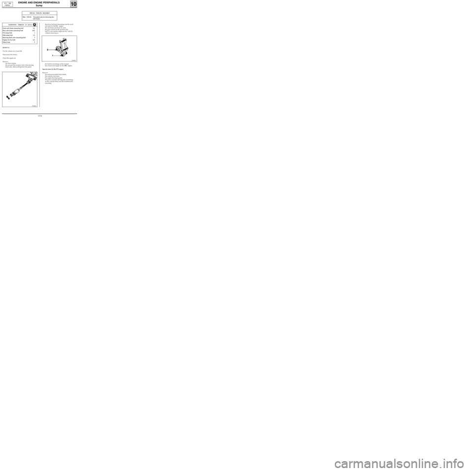
97390S1
- the lower ball joint mountings and the track
rod ends for the
E7J engine,
- the sub-frame and body tie rods,
- the gear control on the gearbox side,
- bolt (1), and slacken engine tie-bar bolt (2),
without removing it,
E7J / F8Q
engines
SPECIAL TOOLING REQUIRED
Mot. 1233-01 Threaded rods for lowering the
sub-frame
13359R1
- the bottom mountings of the bumper,
- the exhaust downpipe for the
F8Q engine.
Special notes for the E7J engine
Remove:
- the exhaust manifold heat shield,
- the catalytic converter,
- the engine flywheel guard,
- the power assisted steering pipe mountings
on the cylinder block and the multifunction
mounting.
10-26
Page 36 of 208
TIGHTENING TORQUES (in daN.m)
TOP AND FRONT OF ENGINE
Timing belt
REMOVAL
Place the vehicle on a two post lift.
Disconnect the battery.
Remove :
- the front right hand wheel,
- the belt from the alternator and the power
assisted steering pump if fitted (see section
07),
- the crankshaft accessories pulley.
11
10267R
SPECIAL TOOLING REQUIRED
Crankshaft accessories pulley
mounting bolt 2 + 90°
Mounting bolt for front right
suspended engine mounting
on engine 6.2
Mounting bolt for front right
suspended engine mounting
on vehicle body 6.2
Timing belt tension wheel nut 5
Mot. 1054TDC pin
Mot. 1135-01 Tool for tensioning timing
belt
Mot. 1273 Tool for checking belt tension
Mot. 1379 Tool for securing engine to
subframe
Mot. 1386 Tool for pre-tensioning timing
belt
Fit tool Mot. 1379. D7F engine
11-1
Page 40 of 208
TOP AND FRONT OF ENGINE
Timing belt
REMOVAL
Place the vehicle on a 2 post lift.
Disconnect the battery.
Fit the engine support tool.
11
13370S
SPECIAL TOOLING REQUIRED
Mot. 591-02 Index pin
Mot. 591-04 Angle tightening wrench
Mot. 1135-01 Tool for tensioning timing
belt
Mot. 1273 Tool for checking belt tension
Wheel bolts 9
Crankshaft pulley bolts 2 + 68° ± 6°
Tension wheel nut 5
Bolt for suspended engine mounting cover 6.2
Nut for suspended engine mounting cover 4.4
13359R
Remove :
- the front right wheel along with the mud-
guard,
- the suspended engine mounting cover,
EQUIPMENT REQUIRED
Engine support tool
- the belts for the alternator and the power
assisted steering pump.
TIGHTENING TORQUES (In daN.m or /and°)
E7J Engine
11-5
Page 43 of 208
TOP AND FRONT OF ENGINE
Timing belt
11
REMOVAL
Place the vehicle on a 2 post lift.
Disconnect the battery.
Remove :
- the front right hand wheel and the mud-
guard,
- the protective plastic covering over the sus-
pended engine mounting cover .
Fit the engine support tool.
SPECIAL TOOLING REQUIRED
Mot. 1054TDC pin
Mot. 1273 Tool for checking belt tension
EQUIPMENT REQUIRED
Engine support tool
14mm torx socket
13370S
Remove :
- the accessories belt,
- the suspended engine mounting cover.
13086R1
Wheel bolts 9
Crankshaft pulley bolt 2 + 115° ± 15°
Tension wheel nut 5
Bolt for suspended engine mounting
cover 6.2
Nut for suspended engine mounting cover 4.4
TIGHTENING TORQUES (in daN.m or/and°)
F8Q Engine
11-8
Page 46 of 208
12mm torx socket
Angular tightening wrench
TOP AND FRONT OF ENGINE
Cylinder head gasket
11
SPECIAL TOOLING REQUIRED
Mot. 591-04 Angle wrench for tightening
cylinder head and index
Mot. 1202 Hose clip pliers
Mot. 1273 Tool for checking belt tension
Mot. 1379 Tool for securing engine to
subframe
EQUIPMENT REQUIRED
TIGHTENING TORQUES (in daN.m)
Crankshaft output mounting bolt 2 + 90°
Mounting bolt for front right suspended
engine mounting on engine 6.2
Mounting bolt for front right suspended
engine mounting on vehicle body 6.2
Timing belt tension wheel nut 5
Wheel bolts 9
REMOVAL
Put the vehicle on a 2 post lift.
Remove the bonnet, and the right hand wheel .
Disconnect the battery.
Drain the cooling circuit.
Fit the engine support tool, Mot. 1379.Remove:
- the timing belt (see method described in
section 11 "Timing belt"),
- the dipstick,
- the brake servo pipe,
- the air filter,
- the accelerator cable,
- the fuel supply and return pipes level with the
timing belt cover on the cylinder head
D7F Engine
11-11