ignition RENAULT KANGOO 1997 KC / 1.G Engine And Peripherals Workshop Manual
[x] Cancel search | Manufacturer: RENAULT, Model Year: 1997, Model line: KANGOO, Model: RENAULT KANGOO 1997 KC / 1.GPages: 208
Page 1 of 208

Renault 1997
77 11 194 226JULY 1997Edition anglaise
"The repair methods given by the manufacturer in this document are based on the
technical specifications current when it was prepared.
The methods may be modified as a result of changes introduced by the
manufacturer in the production of the various component units and accessories
from which his vehicles are constructed"All copyrights reserved by Renault.
Copying or translating, in part or in full , of this document or use of the service part
reference numbering system is forbidden without the prior written authority of
Renault.
C
FC0A - FC0C - FC0D - FC0E - KC0A - KC0C - KC0D - KC0E
Engine and peripherals
ENGINE AND PERIPHERALS
TOP AND FRONT OF ENGINE
FUEL MIXTURE
FUEL SUPPLY -
DIESEL EQUIPMENT
ANTIPOLLUTION
STARTING - CHARGING
IGNITION - INJECTION
COOLING - EXHAUST - FUEL TANK -
ENGINE SUSPENSION
Page 4 of 208
Page
Cooling
Specifications
Filling and bleeding
Testing
Diagram
Water pump
Exhaust
General
Exhaust pipe assembly
Fuel tank
Tank
Sender unit
Pump and sender unit assembly
Engine suspension
Suspended engine mountings19-1
19-2
19-3
19-4
19-7
19-12
19-15
19-17
19-29
19-30
19-32 COOLING - EXHAUST - FUEL TANK -
ENGINE SUSPENSION
19
16-1
16-7 STARTING - CHARGING
Alternator
Starter
16
IGNITION - INJECTION
Ignition
Static ignition
Plugs
Injection
General
Location of components
Centralised coolant temperature
management
Injection fault warning light
Immobiliser function
Computer configuration depending
on gearbox type17
14-1
14-2
14-7
14-11 ANTIPOLLUTION
Test for the presence of lead
Fuel vapour rebreathing
Oil vapour rebreathing
Exhaust gas recirculation
(EGR)
14
17-17
17-18
17-19
17-20
17-22 IGNITION - INJECTION
(continued)
Injection/air conditioning
programming
Idle speed correction
Adaptive idle speed
correction
Richness regulation
Adaptive richness correction
17
Page
17-1
17-3
17-4
17-8
17-13
17-14
17-15
17-16
Contents
Page 47 of 208
TOP AND FRONT OF ENGINE
Cylinder head gasket
11
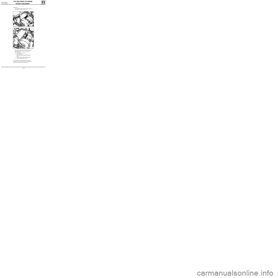
- the canister pipe along with the fuel vapour
rebreathing hoses on the solenoid valve,
- the connectors :
• of the ignition module,
• of the injectors,
• of the idle speed regulation stepping
motor,
• of the throttle position potentiometer,
• of the air temperature sensor.
Extract the hose connecting the water pump to
the heater matrix, and the electrical wiring loom
from the heat shield on the rocker cover.
99940R
Disconnect :
- the spark plug leads using tool (3) which is in-
tegrated to the plastic cover (4),
99894R1
D7F Engine
11-12
Page 51 of 208
TOP AND FRONT OF ENGINE
Cylinder head gasket
11
ADJUSTMENT OF VALVE ROCKERS (IF
NECESSARY)
Partly refit the suspended engine mounting ti-
ming cover on the engine using two bolts.
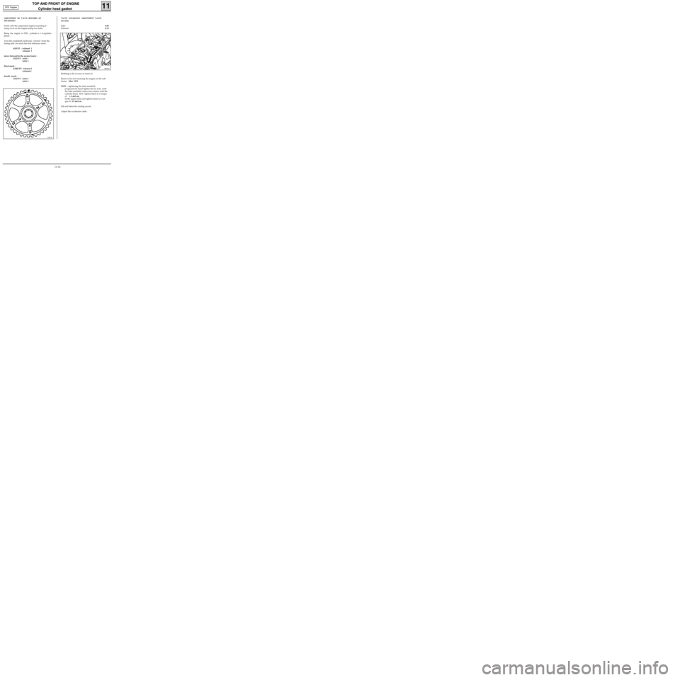
Bring the engine to TDC , cylinder n. 1 in ignition
phase .
Turn the crankshaft clockwise (viewed from the
timing side ) to reach the first reference mark.
ADJUST :exhaust 1
exhaust 3
move forward to the second mark :
ADJUST:inlet 1
inlet 3
third mark :
ADJUST: exhaust 2
exhaust 4
fourth mark :
ADJUST:inlet 2
inlet 4
10072S
99905S
Refitting is the reverse of removal.
Remove the tool retaining the engine on the sub-
frame, Mot. 1379.
NOTE : tightening the inlet manifold :
- progressively hand tighten the six nuts until
the inlet manifold comes into contact with the
cylinder head, then tighten them to a torque
of 1.5 daN.m,
- fit the upper bolts and tighten them to a tor-
que of 0.9 daN.m.
Fill and bleed the cooling circuit.
Adjust the accelerator cable.
VALVE CLEARANCE ADJUSTMENT VALUE
(in mm)
Inlet0.05
Exhaust0.15 D7F Engine
11-16
Page 54 of 208
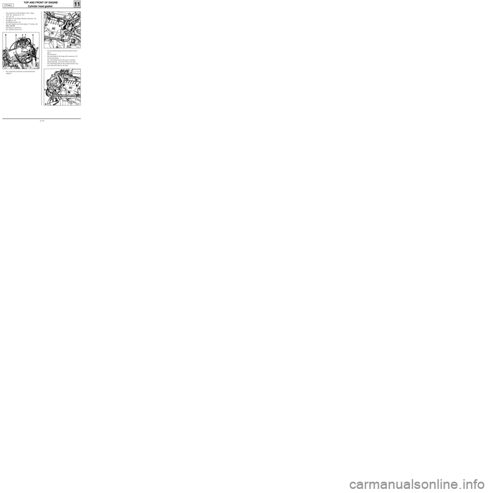
- the heat shield along with the exhaust down-
pipe,
- the alternator,
- the mounting at (8) along with connector (9)
of the pressostat,
- the mounting bolt for the power assisted
steering pump and move this to one side ,
- the mounting bolts for the multi-function sup-
port and move this to one side,
TOP AND FRONT OF ENGINE
Cylinder head gasket
11
13365S
13364R1
13360R
- the connectors and hoses on the thermostat
support , - the connectors of the ignition coils, along
with the connector at (1),
- the coil (2),
- the pipes at (3) along with the connector (4),
- the pipe at (5),
- the lifting bracket (6),
- the fuel supply and return pipes (7) using tool
Mot. 1311-06,
- the injector connectors,
- the cylinder head cover , E7J Engine
11-19
Page 67 of 208
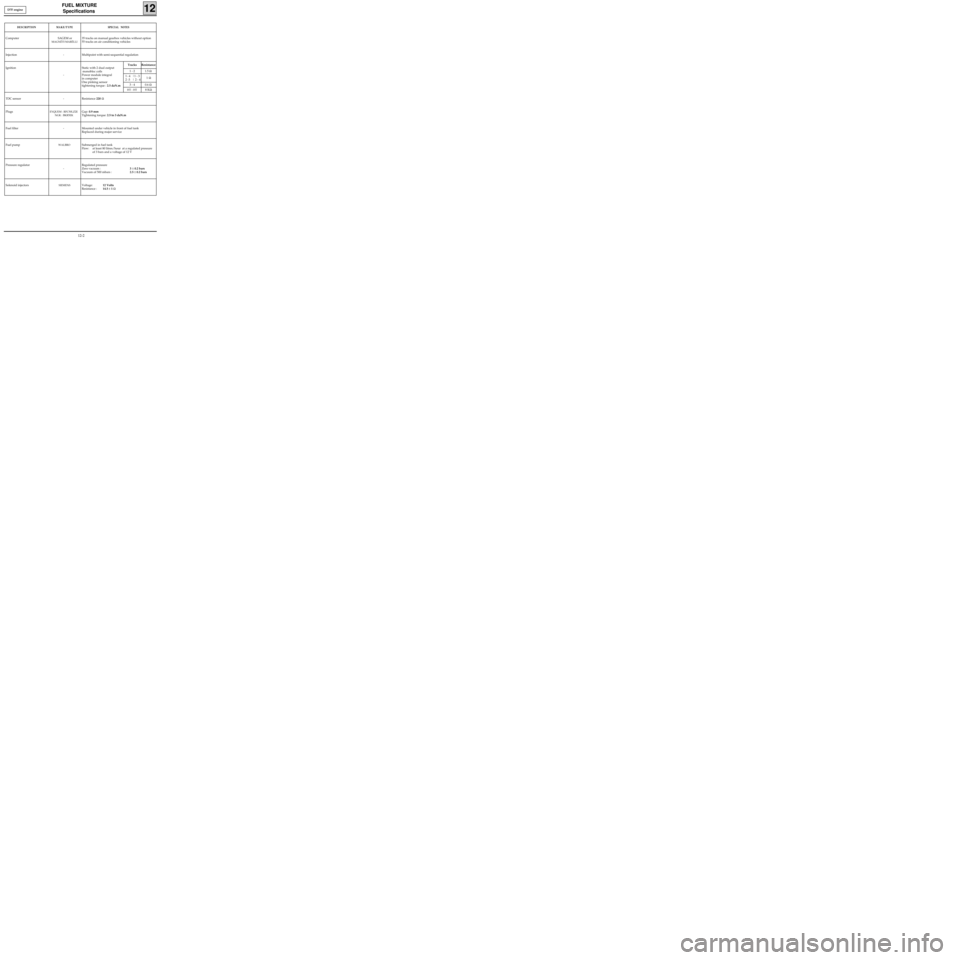
FUEL MIXTURE
Specifications
12
DESCRIPTIONMAKE/TYPESPECIAL NOTES
Computer SAGEM or
MAGNÉTI MARÉLLI
35 tracks on manual gearbox vehicles without option
55 tracks on air conditioning vehicles
Injection - Multipoint with semi-sequential regulation
Ignition
-Static with 2 dual output
monobloc coils
Power module integral
in computer
One pinking sensor
tightening torque : 2.5 daN.m
TDC sensor - Resistance 220 Ω
Plugs
EYQUEM : RFC50LZ2E
NGK : BKR5EKGap: 0.9 mm
Tightening torque: 2.5 to 3 daN.m
Fuel filter - Mounted under vehicle in front of fuel tank
Replaced during major service
Fuel pump
WALBROSubmerged in fuel tank
Flow: at least 80 litres/hour at a regulated pressure
of 3 bars and a voltage of 12 V
Pressure regulator
-Regulated pressure
Zero vacuum :3 ± 0.2 bars
Vacuum of 500 mbars :2.5 ± 0.2 bars
Solenoid injectors
SIEMENSVoltage:12 Volts
Resistance :14.5 ± 1 Ω
Tracks Resistance
1 - 2 1.5 Ω
1
- 4 |1 - 3
2 -3 | 2 - 41 Ω
3 - 4 0.6 Ω
HT - HT8 KΩ
D7F engine
12-2
Page 70 of 208
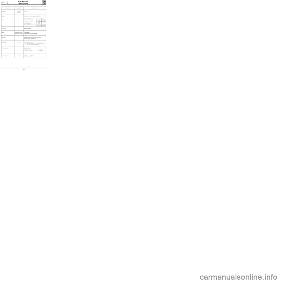
FUEL MIXTURE
Specifications
12
DESCRIPTIONMAKE/TYPESPECIAL NOTES
ComputerSIEMENS
FENIX 555tracks
Injection - Multipoint with semi-sequential regulation
Ignition
-Static with 2 dual output
monobloc coils
Power module integral
in computer
One pinking sensor
tightening torque : 2.5 daN.m
TDC sensor - Resistance 220 Ω
Plugs
EYQUEM : RFC52LS
CHAMPION
: RC10PYC
Gap: 0.9 mm
Tightening torque: 2.5 to 3 daN.m
Fuel filter - Mounted under vehicle in front of fuel tank
Replaced during major service
Fuel pump
WALBROSubmerged in fuel tank
Flow: at least 80 litres/hour at a regulated pressure
of 3 bars and a voltage of 12 V
Pressure regulator
-
Regulated pressure
Zero vacuum :3 ± 0.2 bars
Vacuum of 500 mbars :2.5 ± 0.2 bars
Solenoid injectors
SIEMENSVoltage:12 Volts
Resistance :14.5 ± 1 Ω
Tracks Resistance
1 - 2 0.5 Ω
1 - 3
2 -31 Ω
HT - HT10 KΩ
E7J engine
12-5
Page 92 of 208
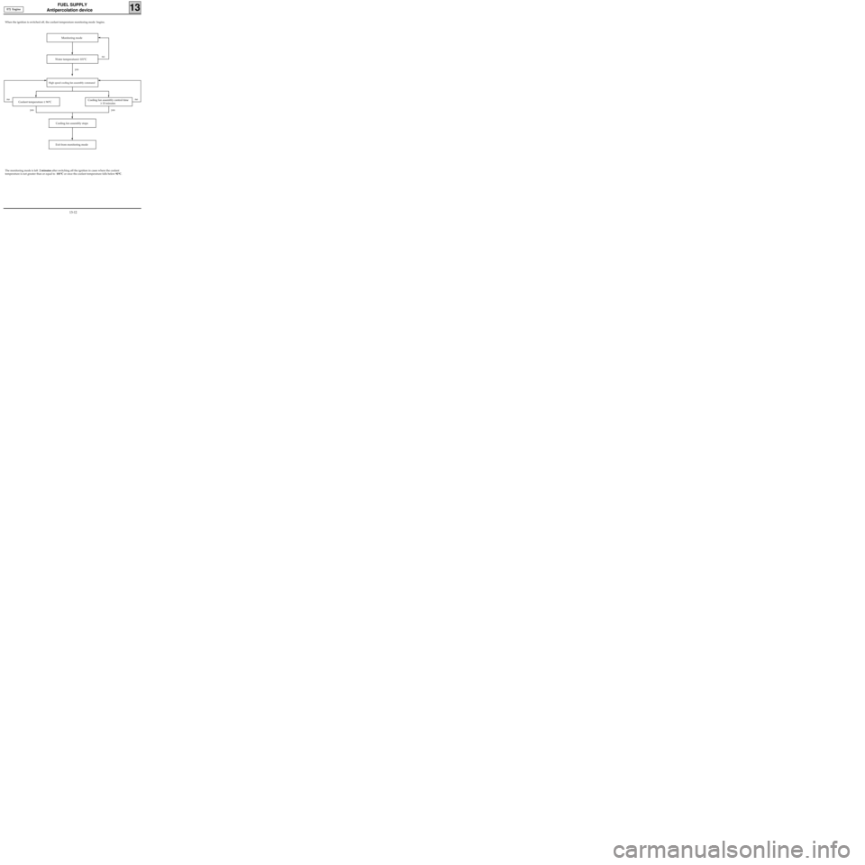
FUEL SUPPLY
Antipercolation device
13
When the ignition is switched off, the coolant temperature monitoring mode begins.
E7J Engine
Monitoring mode
Water temperature≥ 101°C
Coolant temperature ≤ 96°C Cooling fan assembly control time
≥ 10 minutes
Cooling fan assembly stops
Exit from monitoring mode
The monitoring mode is left 2 minutes after switching off the ignition in cases where the coolant
temperature is not greater than or equal to 101°C or once the coolant temperature falls below 92°C.
no
yes
nono
yes yes
High speed cooling fan assembly command
13-12
Page 98 of 208
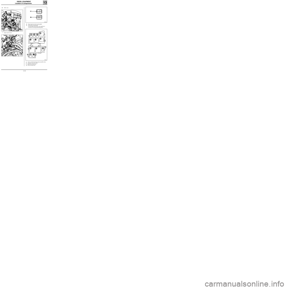
DIESEL EQUIPMENT
Location of components
13
20 EGR valve
13047-1R
7Engine speed sensor
13048R
87970R
17Diesel injection fault warning light
18Preheating warning light
Warning light illuminates when ignition is
switched on during preheating phase.
12839S
C Power assisted steering pump assembly relay
HAltimetric corrector relay
LInjection locking relay
MDiesel heating relay
13-18
Page 108 of 208
DIESEL EQUIPMENT
Load potentiometer
13
In the factory, vehicles are programmed with the full load position. (memorising the voltage delivered by the
potentiometer in the full load position). This value is used to adjust the load potentiometer after it has been
replaced. It is therefore essential, if the diesel injection computer has to be replaced during the vehicle’s li-
fetime , to carry out this programming (G31*).
If it is necessary to replace the load potentiometer, in order to adjust it we compare the voltage delivered by
the potentiometer in full load position, with the value memorised. The new potentiometer is said to be cor-
rectly adjusted when the two voltages are equal. This is displayed on the
XR25. G32* indicates the diffe-
rence in voltage between the value memorised and the one from the potentiometer. The adjustment is cor-
rect if this value is equal to 0 in the full load position.
The potentiometer and the computer cannot be replaced at the same time (if necessary, replace the poten-
tiometer first and then the computer).
REPLACEMENT OF THE LOAD POTENTIOMETER (operation to be carried out by two people)
Remove the three terminals for the load potentiometer from the 10 track pump connector (see method
described in section 13 "Advance solenoid valve").
Remove the two bolts mounting the faulty potentiometer, extract this, and fit the new potentiometer .
Hand tighten the two bolts mounting the potentiometer but do not lock them - it should be possible to turn
the potentiometer body .
Connect the
XR25, and switch on the ignition.
Set the selector to S8.
Enter code
Press down on the accelerator pedal (full load position). Do not act directly on the load lever.
Holding the full load position, turn the potentiometer body until the value 0 appears on the XR25 display (if
you are too far from the 0 value, the screen will display HL , which means "Hors Limite"= "Off limits". Just
to turn the potentiometer body to obtain the display of a decimal value).
Tighten the two bolts mounting the potentiometer in the full load position, when the value read is 0. D
34then
G32*
13-28