reset RENAULT KANGOO 1997 KC / 1.G Engine And Peripherals Workshop Manual
[x] Cancel search | Manufacturer: RENAULT, Model Year: 1997, Model line: KANGOO, Model: RENAULT KANGOO 1997 KC / 1.GPages: 208
Page 81 of 208

FUEL SUPPLY
Fuel cut off in case of an impact
13
OBJECTIVE
The main function of this feature is to avoid any
fires that may result from the leakage of fuel du-
ring an accident. In order to achieve this, all
components pumping fuel from the fuel tank will
automatically stop functioning during and imme-
diately after the impact. They can then only be
made to operate again by a mechanical action car-
ried out by the driver or the repairer.
DESCRIPTION
The system consists simply of an inertia switch (1),
which:
- detects the impact,
- and thus cuts off the electrical circuit.
13051R
This is fitted:
• in petrol engines, between track 1 of the
pump relay (236) and the + 12 V supply ,
• in diesel engines, between the + supply and
the electrical solenoid (or the coded solenoid
valve if the vehicle is fitted with an engine im-
mobiliser).
OPERATING PRINCIPLE
During the impact, the ball of the inertia switch
moves up and interrupts the electrical connec-
tion.
In petrol engines, the + supply of the pump relay
control circuit (236) is cut. Neither the pump or
the injectors will receive any further supply of
electricity .
The fuel contained in the tank is actually isolated.
In diesel engines, the + supply of the electrical
solenoid or of the coded solenoid is cut off.
The pump can no longer take in fuel, and there is
no longer any high pressure. All risk of fire due to
the outlet of diesel fuel at high pressure onto the
engine is removed.
RESETTING AND OPERATING THE SWITCH
In order to reset the inertia switch, it is sufficient
to press it down in order to replace the ball bea-
ring in its original position .
IMPORTANT: for petrol engines, , having reset
the switch, it is
VITAL to erase the memory of the
computer, using the
XR25. The injection compu-
ter will memorise a pump relay fault once the
system has gone into operation .
13-1
Page 169 of 208

INJECTION
Adaptive idle speed correction
17
PRINCIPLE
Under normal warm engine operating conditions , the R.C.O. idle speed value at #12 varies between a
high value and a low value, until the nominal idle speed is obtained .
It is possible that during variations in the operation of the vehicle (running in, engine wear..), that the
R.C.O. idle speed value could become close to the highest or lowest values.
The adaptive correction (#21) of the
R.C.O. idle speed (#12) allows the slow variations in the engine air re-
quirement to be corrected, so that the
R.C.O. (#12) is recentred to an average nominal value.
This correction only becomes effective if the coolant temperature is higher than 75°C, 20 seconds after
starting the engine and if the nominal idle speed regulation phase has been reached.
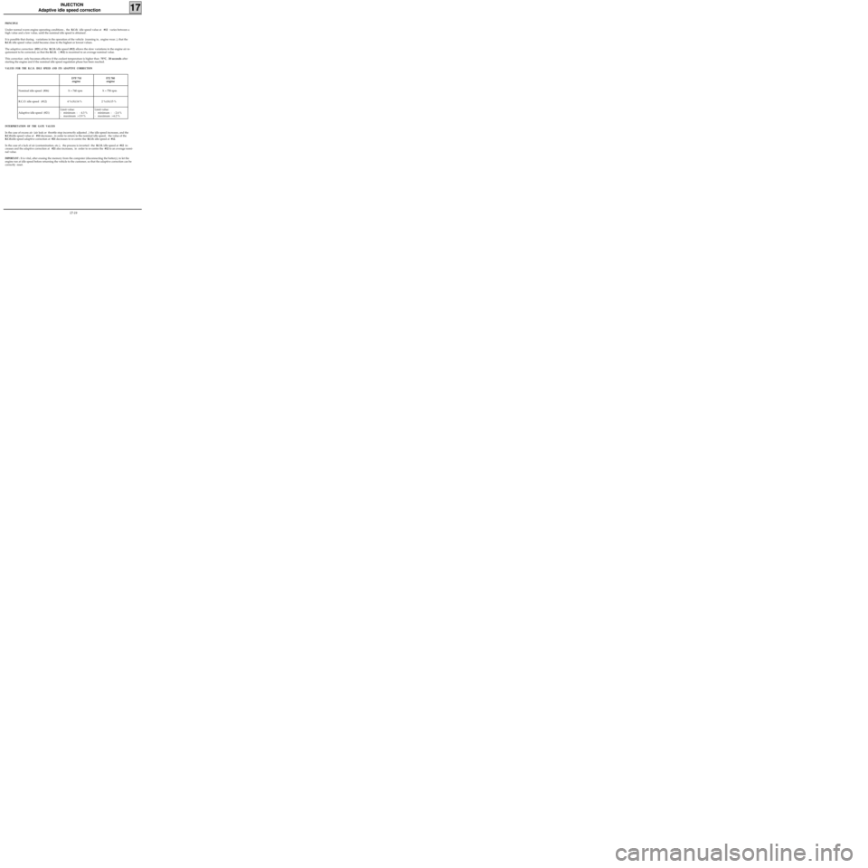
VALUES FOR THE R.C.O. IDLE SPEED AND ITS ADAPTIVE CORRECTION
D7F 710
engineE7J 780
engine
Nominal idle speed (#06) X = 740 rpm X = 750 rpm
R.C.O. idle speed (#12) 4 %≤X≤14 % 2 %≤X≤15 %
Adaptive idle speed (#21)Limit value:
- minimum : - 4.3 %
- maximum :+3.9 %Limit value:
- minimum : - 2.4 %
- maximum :+6.2 %
INTERPRETATION OF THE GATE VALUES
In the case of excess air (air leak or throttle stop incorrectly adjusted ..) the idle speed increases, and the
R.C.O.idle speed value at #12 decreases , in order to return to the nominal idle speed; the value of the
R.C.O.idle speed adaptive correction at #21 decreases to re-centre the R.C.O. idle speed at #12.
In the case of a lack of air (contamination, etc.), the process is inverted : the
R.C.O. idle speed at #12 in-
creases and the adaptive correction at #21 also increases, in order to re-centre the #12 to an average nomi-
nal value.
IMPORTANT : It is vital, after erasing the memory from the computer (disconnecting the battery), to let the
engine run at idle speed before returning the vehicle to the customer, so that the adaptive correction can be
correctly reset.
17-19