ignition RENAULT KANGOO 1997 KC / 1.G Foult Finding - Injection Workshop Manual
[x] Cancel search | Manufacturer: RENAULT, Model Year: 1997, Model line: KANGOO, Model: RENAULT KANGOO 1997 KC / 1.GPages: 363
Page 197 of 363
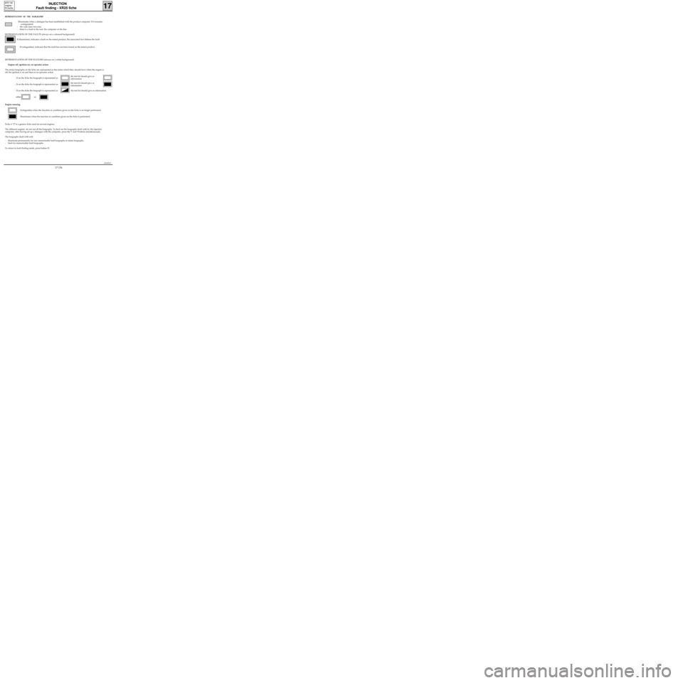
REPRESENTATION OF THE BARGRAPHS
Illuminates when a dialogue has been established with the product computer. If it remains
extinguished:
- the code does not exist,
- there is a fault in the tool, the computer or the line
REPRESENTATION OF THE FAULTS (always on a coloured background)
If illuminated, indicates a fault on the tested product, the associated text defines the fault.
If extinguished, indicates that the fault has not been found on the tested product.
REPRESENTATION OF THE STATUSES (always on a white background)
Engine off, ignition on, no operator action
The status bargraphs on the fiche are represented as the status which they should have when the engine is
off, the ignition is on and there is no operator action
- If on the fiche the bargraph is represented as
- If on the fiche the bargraph is represented as
- If on the fiche the bargraph is represented as the test kit should give as information
either or
Engine running
Extinguishes when the function or condition given on the fiche is no longer performed.
Illuminates when the function or condition given on the fiche is performed
Fiche n° 27 is a generic fiche used for several engines.
The different engines do not use all the bargraphs. To find out the bargraphs dealt with by the injection
computer, after having set up a dialogue with the computer, press the V and 9 buttons simultaneously.
The bargraphs dealt with will:
- illuminate permanently for non memorisable fault bargraphs or status bargraphs,
- flash for memorisable fault bargraphs.
To return to fault finding mode, press button D.
JSA052.0
INJECTION
Fault finding - XR25 fiche
17
D7F 710
engine -
55 tracks
the test kit should give as
information
the test kit should give as
information
17-154
Page 198 of 363
Connect the bornier in place of the computer and check the insulation and continuity of the line:
Computer 18 Earth
Computer 2 Earth
Computer 3 Earth
Computer 11 7 Diagnostic socket
Computer 38 15 Diagnostic socket
Computer 1 5 Main relay
Computer 40 2 Main relay
Computer 48 2 Fuel pump relay
Repair if necessary.
JSA052.0
INJECTION
Fault finding - Interpretation of XR25 bargraphs17
D7F 710
engine -
55 tracks
Erase the computer memory using G0**.
Try to start the engine. Switch the ignition on, then deal with the other faults.
Remember to carry out a status and parameter check.AFTER REPAIR
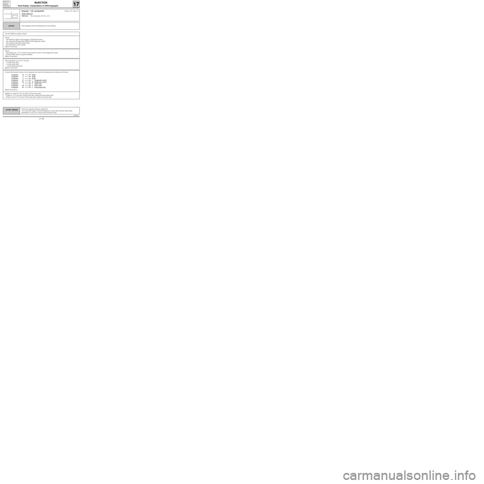
Bargraph 1 RH extinguishedFiche n° 27 side 1/2
XR25 CIRCUIT
XR25 aid:No connection, CO, CC-, CC+
1
This bargraph must be illuminated for fault findingNOTES
Test the XR25 on another vehicle.
Check:
- the injection, engine and passenger compartment fuses,
- the connection between the XR25 and the diagnostic socket,
- the position of the ISO selector (S8),
- the conformity of the cassette.
Repair if necessary.
Check:
- the presence of + 12 V on track 16 and earth on track 5 of the diagnostic socket,
- that the XR25 cable is in good condition.
Repair if necessary.
Check, ignition on, for 12 V on track:
- 1 on the main relay,
- 3 on the main relay,
- 1 on the fuel pump relay.
Repair if necessary.
Ignition on, check for 12 V on track 5 of the main relay:
- If there is 12 V on track 5 of the main relay: replace the fuel pump relay.
- If there is not 12 V on track 5 of the main relay: replace the main relay.
17-155
Page 199 of 363
JSA052.0
INJECTION
Fault finding - Interpretation of XR25 bargraphs17
D7F 710
engine -
55 tracks
Erase the computer memory using G0**.
Try to start the engine. Switch the ignition on, then deal with the other faults.
Remember to carry out a status and parameter check.AFTER REPAIR
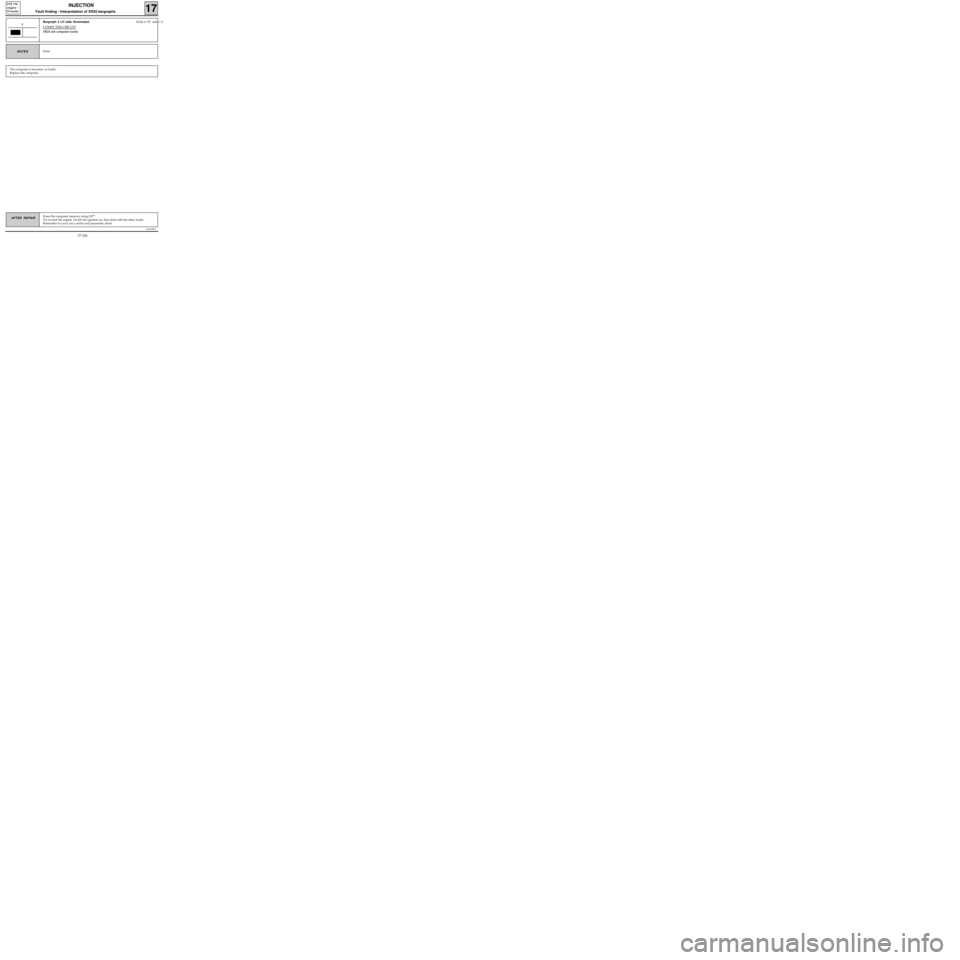
Bargraph 2 LH side illuminated. Fiche n° 27 side 1/2
COMPUTER CIRCUIT
XR25 aid: computer faulty
2
NoneNOTES
The computer is incorrect or faulty.
Replace the computer.
17-156
Page 200 of 363
JSA052.0
INJECTION
Fault finding - Interpretation of XR25 bargraphs17
D7F 710
engine -
55 tracks
Erase the computer memory using G0**.
Try to start the engine. Switch the ignition on, then deal with the other faults.
Remember to carry out a status and parameter check.AFTER REPAIR
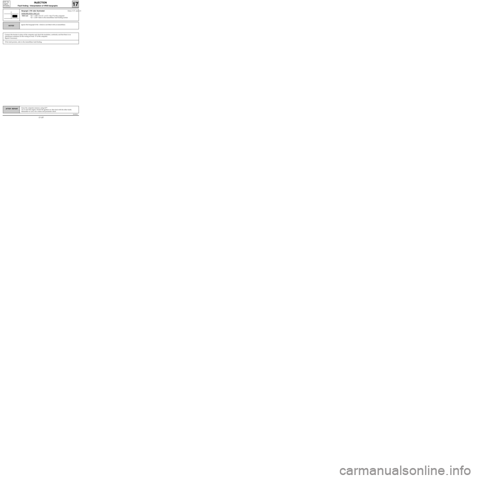
Bargragh 2 RH side illuminated Fiche n° 27 side 1/2
IMMOBILISER CIRCUIT
XR25 aid:*22 = 1 dEF CO, CC- or CC+ line 37 of the computer
*22 = 2 dEF Refer to the immobiliser fault finding section
2
Ignore this bargraph if the vehicle is not fitted with an immobiliser.NOTES
Connect the bornier in place of the computer and check the insulation, continuity and that there is no
interference resistance on the wiring on track 37 of the computer.
Repair if necessary.
If the fault persists, refer to the immobiliser fault finding.
17-157
Page 201 of 363
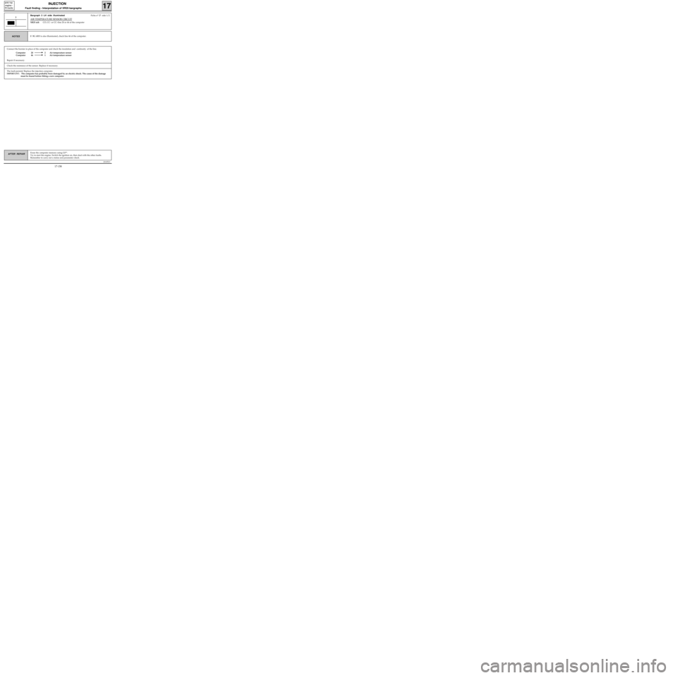
Connect the bornier in place of the computer and check the insulation and continuity of the line.
Computer 20 2 Air temperature sensor
Computer 46 1 Air temperature sensor
Repair if necessary.
JSA052.0
INJECTION
Fault finding - Interpretation of XR25 bargraphs17
D7F 710
engine -
55 tracks
Erase the computer memory using G0**.
Try to start the engine. Switch the ignition on, then deal with the other faults.
Remember to carry out a status and parameter check.AFTER REPAIR
Bargraph 3 LH side illuminatedFiche n° 27 side 1/2
AIR TEMPERATURE SENSOR CIRCUIT
XR25 aid:CO, CC- or CC+line 20 or 46 of the computer
3
If BG 6RH is also illuminated, check line 46 of the computer.NOTES
Check the resistance of the sensor. Replace if necessary.
The fault persists! Replace the injection computer.
IMPORTANT: The computer has probably been damaged by an electric shock. The cause of the damage
must be found before fitting a new computer.
17-158
Page 202 of 363
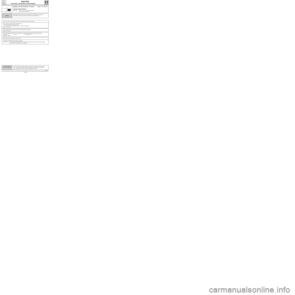
Connect the bornier in place of the computer and check the insulation and continuity of the line:
Computer 17 C Oxygen sensor
Repair if necessary.
JSA052.0
INJECTION
Fault finding - Interpretation of XR25 bargraphs17
D7F 710
engine -
55 tracks
Turn the engine, switch the ignition on and erase the computer memory using
G0**. Try to start the engine. Switch the ignition on, then deal with the other
faults. Remember to carry out a status and parameter check.AFTER REPAIR
Bargraph 3 RH side illuminated or flashing Fiche n° 27 side 1/2
OXYGEN SENSOR CIRCUIT
XR25 aid:CO, CC- or CC+line 17 of the computer
CO line 18 of the computer
3
If BG 3RH is flashing, increase the engine speed to 2500rpm for 5 minutes.
If BG 3RH becomes permanently illuminated, deal with the fault.
NOTES
Check the connection and the condition of the connector on the oxygen sensor.
Check, ignition on during the timed phase, for :
- earth on track B of the oxygen sensor,
- + 12 V after the fuel pump relay on track A of the oxygen sensor.
Repair if necessary.
Check for the presence of earth on track 18 of the injection computer.
Repair if necessary.
The fault persists. Replace the oxygen sensor.
The fault persists! Replace the injection computer.
IMPORTANT: The computer has probably been damaged by an electric shock. The cause of the damage
must be found before fitting a new computer.
17-159
Page 203 of 363

Connect the bornier in place of the computer and check the insulation and continuity of the line:
Computer 44 1 Coolant temperature sensor
Computer 15 2 Coolant temperature sensor
Repair if necessary.
JSA052.0
INJECTION
Fault finding - Interpretation of XR25 bargraphs17
D7F 710
engine -
55 tracks
Erase the computer memory using G0**.
Try to start the engine. Switch the ignition on, then deal with the other faults.
Remember to carry out a status and parameter check.AFTER REPAIR
Bargraph 4 LH side illuminated Fiche n° 27 side 1/2
COOLANT TEMPERATURE SENSOR CIRCUIT
XR25 aid :CO, CC- or CC+line 44 or 15 of the computer
4
If BG 6LH or BG 5LH is also illuminated , check line 44 of the computer. For certain
faults, BG 4LH is only permanently illuminated when the engine is running.NOTES
The fault persists! Replace the injection computer.
IMPORTANT: The computer has probably been damaged by an electric shock. The cause of the damage
must be found before fitting a new computer.
Check the resistance of the sensor. Replace it if necessary.
17-160
Page 204 of 363
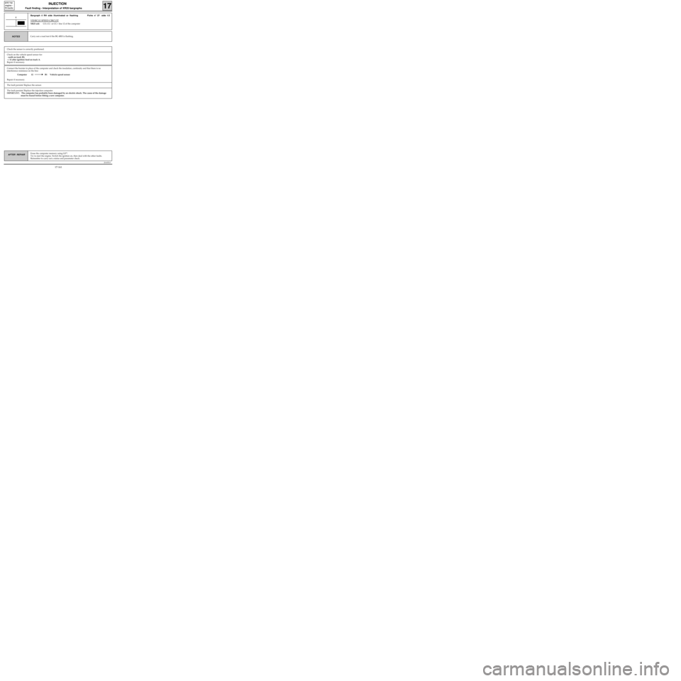
Connect the bornier in place of the computer and check the insulation, continuity and that there is no
interference resistance on the line:
Computer 12 B1 Vehicle speed sensor
Repair if necessary.
JSA052.0
INJECTION
Fault finding - Interpretation of XR25 bargraphs17
D7F 710
engine -
55 tracks
Erase the computer memory using G0**.
Try to start the engine. Switch the ignition on, then deal with the other faults.
Remember to carry out a status and parameter check.AFTER REPAIR
Bargraph 4 RH side illuminated or flashing Fiche n° 27 side 1/2
VEHICLE SPEED CIRCUIT
XR25 aid:CO, CC- or CC+ line 12 of the computer
4
Carry out a road test if the BG 4RH is flashing.NOTES
Check the sensor is correctly positioned.
Check on the vehicle speed sensor for:
- earth on track B2,
-+ 12 after ignition feed on track A.
Repair if necessary.
The fault persists! Replace the sensor.
The fault persists! Replace the injection computer.
IMPORTANT: The computer has probably been damaged by an electric shock. The cause of the damage
must be found before fitting a new computer.
17-161
Page 205 of 363
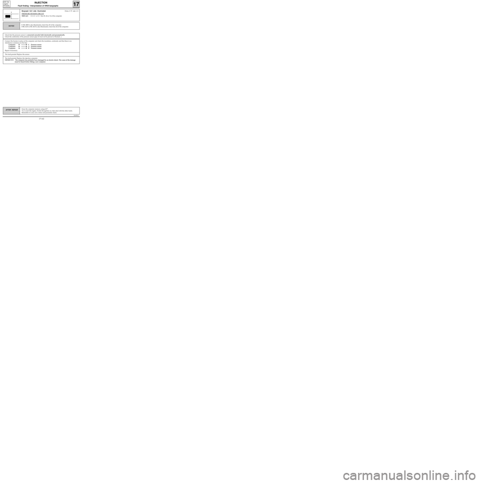
Connect the bornier in place of the computer and check the insulation, continuity and that there is no
interference resistance on the line:
Computer 45 C Pressure sensor
Computer 44 A Pressure sensor
Computer 16 B Pressure sensor
Repair if necessary.
JSA052.0
INJECTION
Fault finding - Interpretation of XR25 bargraphs17
D7F 710
engine -
55 tracks
Erase the computer memory using G0**.
Try to start the engine. Switch the ignition on, then deal with the other faults.
Remember to carry out a status and parameter check.AFTER REPAIR
Bargraph 5LH side illuminatedFiche n° 27 side 1/2
PRESSURE SENSOR CIRCUIT
XR25 aid :CO, CC- or CC+ line 45, 44 or 16 of the computer
5
If BG 6RH is also illuminated, check line 45 of the computer.
If BG 6LH or BG 4LH is also illuminated, check line 44 of the computer.NOTES
Check that the pressure sensor is connected correctly both electrically and pneumatically.
Check the conformity of the pressure sensor pipe (it must not be pierced or blocked...).
The fault persists! Replace the injection computer.
IMPORTANT: The computer has probably been damaged by an electric shock. The cause of the damage
must be found before fitting a new computer.
The fault persists! Replace the sensor.
17-162
Page 206 of 363
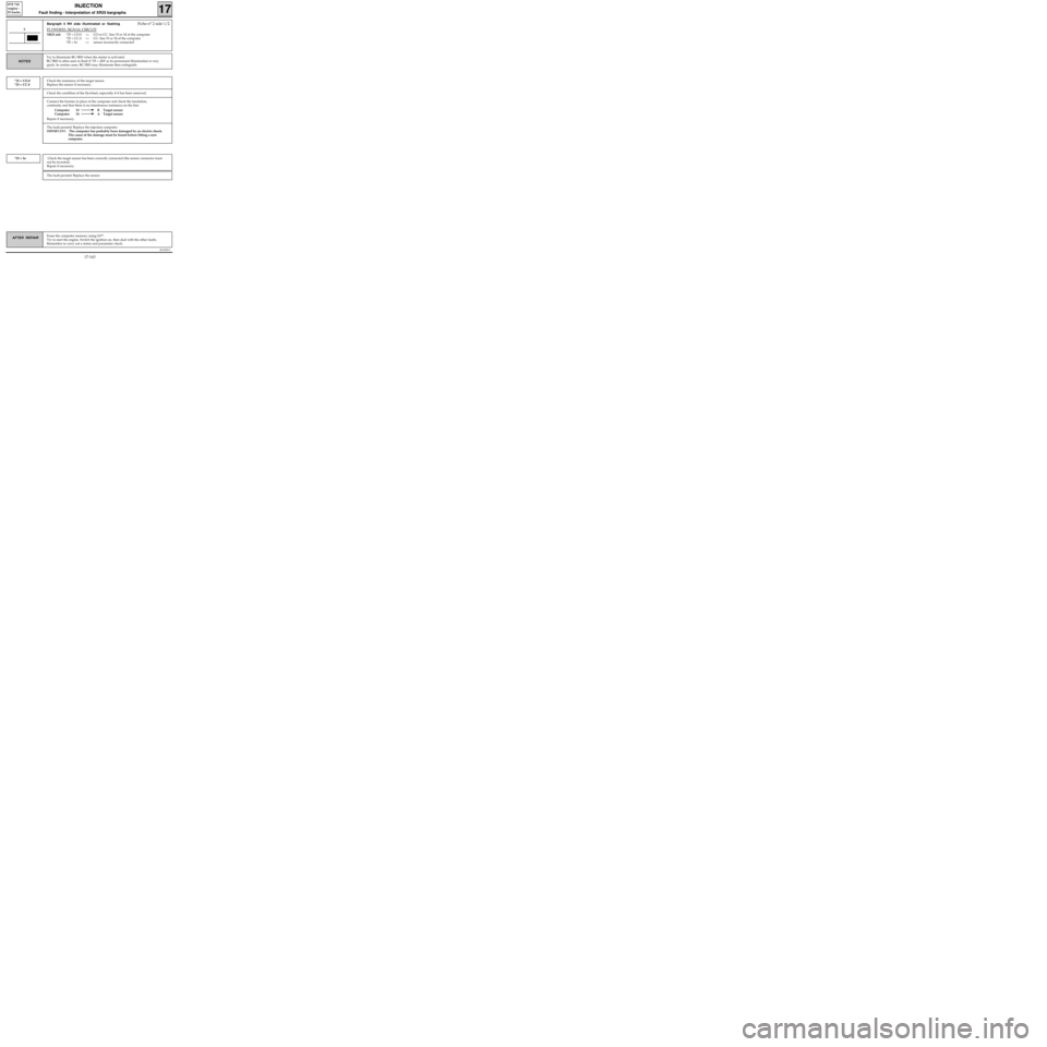
Connect the bornier in place of the computer and check the insulation,
continuity and that there is no interference resistance on the line:
Computer 33 B Target sensor
Computer 34 A Target sensor
Repair if necessary.
JSA052.0
INJECTION
Fault finding - Interpretation of XR25 bargraphs17
D7F 710
engine -
55 tracks
Erase the computer memory using G0**.
Try to start the engine. Switch the ignition on, then deal with the other faults.
Remember to carry out a status and parameter check.AFTER REPAIR
Bargraph 5 RH side illuminated or flashingFiche n° 2 side 1/2
FLYWHEEL SIGNAL CIRCUIT
XR25 aid:*25 = CO.0 =>CO or CC- line 33 or 34 of the computer
*25 = CC.0 =
>CC- line 33 or 34 of the computer
*25 = In =
>sensor incorrectly connected
5
Try to illuminate BG 5RH when the starter is activated.
BG 5RH is often seen to flash if *25 = dEF as its permanent illumination is very
quick. In certain cases, BG 5RH may illuminate then extinguish.
NOTES
Check the resistance of the target sensor.
Replace the sensor if necessary.*25 = CO.0
*25 = CC.0
Check the condition of the flywheel, especially if it has been removed.
The fault persists! Replace the injection computer.
IMPORTANT: The computer has probably been damaged by an electric shock.
The cause of the damage must be found before fitting a new
computer.
Check the target sensor has been correctly connected (the sensor connector must
not be inverted).
Repair if necessary.*25 = In
The fault persists! Replace the sensor.
17-163