ignition RENAULT KANGOO 1997 KC / 1.G Foult Finding - Injection Workshop Manual
[x] Cancel search | Manufacturer: RENAULT, Model Year: 1997, Model line: KANGOO, Model: RENAULT KANGOO 1997 KC / 1.GPages: 363
Page 217 of 363
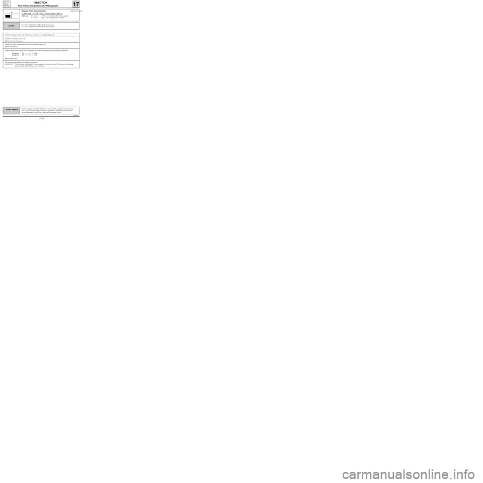
Connect the bornier in place of the computer and check the insulation and continuity of the line :
Computer 29 2 Coil
Computer 28 1 Coil
Repair if necessary.
JSA052.0
INJECTION
Fault finding - Interpretation of XR25 bargraphs17
D7F 710
engine -
55 tracks
Turn the engine, switch the ignition on and erase the computer memory using
G0**. Try to start the engine. Switch the ignition on, then deal with the other
faults. Remember to carry out a status and parameter check.AFTER REPAIR
Bargraph 16 LH side illuminated Fiche n° 27 side 1
COMPUTER MPA CONNECTION CIRCUIT
XR25 aid:*16 = XX.CO=> CO or CC- line 28 or 29 of the computer
*16 = XX.CC=> CC+ line 28 or 29 of the computer
16
XX = 14 => Cylinder 1 or 4 line 28 of the computer
XX = 23 =
> Cylinder 2 or 3 line 29 of the computerNOTES
Check the resistance of the coil.
Replace the coil if necessary.
Check the + after ignition feed to the coil concerned on track 3.
Repair if necessary.
The fault persists! Replace the injection computer.
IMPORTANT: The computer has probably been damaged by an electric shock. The cause of the damage
must be found before fitting a new computer.
Check the hygiene of the anti-interference condenser on track 4 of the coil.
17-174
Page 218 of 363
JSA052.0
INJECTION
Fault finding - Status and parameter checks
17
D7F 710
engine -
55 tracks
Engine stopped, ignition on.NOTES
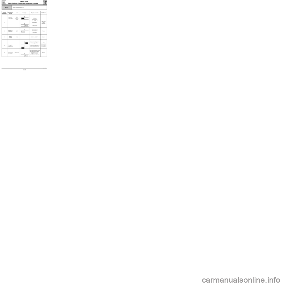
Order of
operationsFunction to be
checkedAction Bargraph Display and notes Fault finding
1Dialogue
with XR25D13
(selector
on S8)Fault test
9.NJ
Use fiche 27
Code present
Deal with
fault
bargraph
2Change to
status testG01*
10.NJ
Status testNone
3Battery
voltage# 0411.8 < X < 13.2 V
DIAG 1
4Computer
configurationComputer configured to
manual gearbox
Computer configured to
automatic transmissionSee Fiche
’Reminder C’
to configure
the vehicle
5Immobiliser
(if option)Ignition onThis status bargraph must
be extinguished when
the ignition is on to
indicate that the
immobiliser is not active.
DIAG 12
1
19
19
1
1
3
17-175
Page 219 of 363
JSA052.0
INJECTION
Fault finding - Status and parameter checks
17
D7F 710
engine -
55 tracks
Engine stopped, ignition on.NOTES
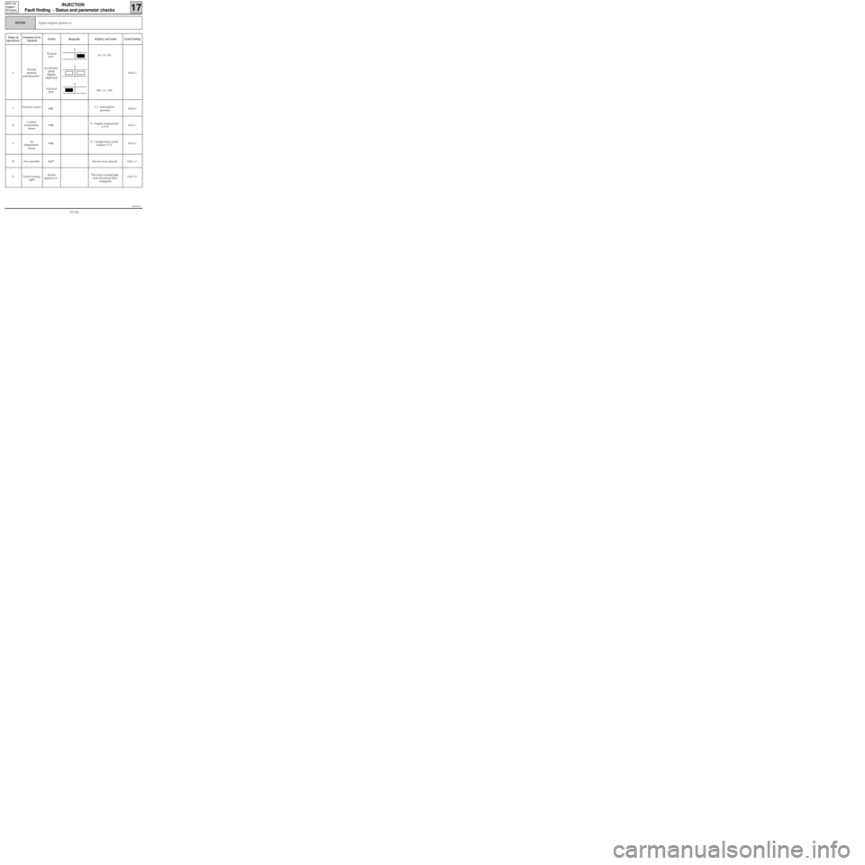
Order of
operationsFunction to be
checkedAction Bargraph Display and notes Fault finding
6Throttle
position
potentiometer
.No load
# 17
Accelerator
pedal
slightly
depressed
Full load
# 1710 < X < 50
185 < X < 245
DIAG 2
7Pressure sensor
# 01X = Atmospheric
pressureDIAG 9
8Coolant
temperature
sensor# 02X = Engine temperature
± 5 °CDIAG 3
9Air
temperature
sensor# 03X = Temperature under
bonnet ± 5 °CDIAG 4
10 Fan assemblyG17*The fan must operateDIAG 17
11 Fault warning
lightSwitch
ignition onThe fault warning light
must illuminate then
extinguishDIAG 19
2
2
2
17-176
Page 220 of 363
JSA052.0
INJECTION
Fault finding - Status and parameter checks
17
D7F 710
engine -
55 tracks
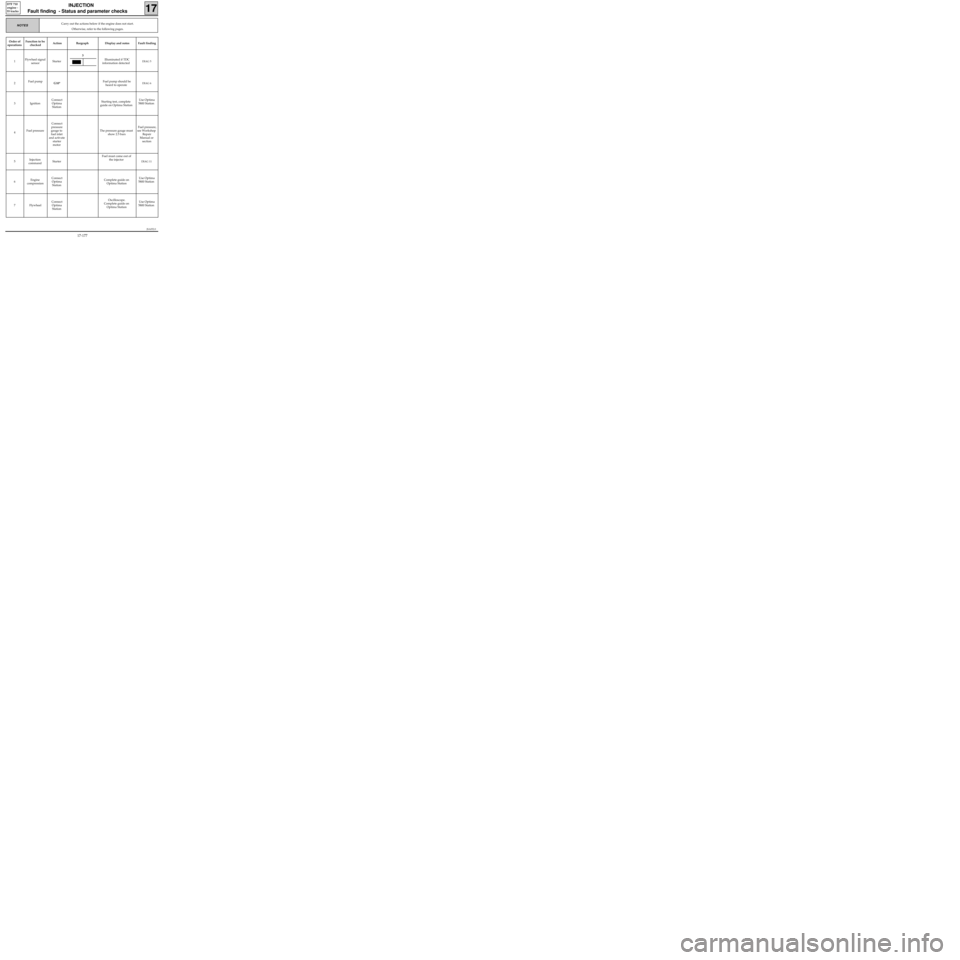
Carry out the actions below if the engine does not start.
Otherwise, refer to the following pages.NOTES
Order of
operationsFunction to be
checkedAction Bargraph Display and notes Fault finding
1Flywheel signal
sensorStarterIlluminated if TDC
information detected
DIAG 5
2Fuel pump
G10*Fuel pump should be
heard to operateDIAG 6
3 IgnitionConnect
Optima
StationStarting test, complete
guide on Optima StationUse Optima
5800 Station
4Fuel pressureConnect
pressure
gauge to
fuel inlet
and activate
starter
motorThe pressure gauge must
show 2.5 bars Fuel pressure,
see Workshop
Repair
Manual or
section
5Injection
commandStarterFuel must come out of
the injector
DIAG 11
6Engine
compressionConnect
Optima
StationComplete guide on
Optima StationUse Optima
5800 Station
7 FlywheelConnect
Optima
StationOscilloscope.
Complete guide on
Optima StationUse Optima
5800 Station
3
17-177
Page 224 of 363
JSA052.0
INJECTION
Fault finding - Status and parameter interpretation17
D7F 710
engine -
55 tracks
AFTER REPAIRStart the status and parameter check again from the beginning.
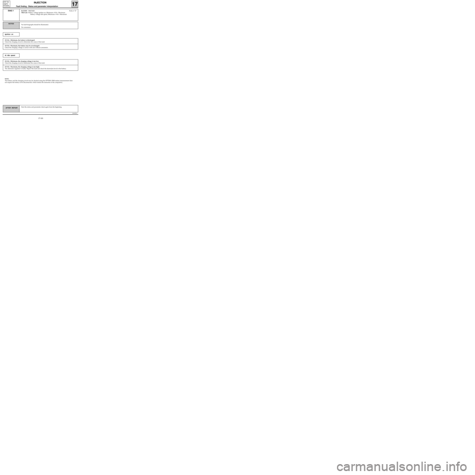
DIAG 1BATTERY VOLTAGEFiche n° 27
XR25 aid: Battery voltage ignition on, Minimum< # 04 < Maximum
Battery voltage idle speed, Minimum< # 04 < Maximum
No fault bargraphs should be illuminated.
No consumersNOTES
If # 04 < Minimum, the battery is discharged:
Check the charging circuit to determine the cause of this fault.
Ignition on
If # 04 > Maximum, the battery may be overcharged:
Check the charging voltage is correct with and without consumers.
If # 04 < Minimum, the charging voltage is too low:
Check the charging circuit to determine the cause of this fault.
At idle speed
If # 04 > Maximum, the charging voltage is too high:
The alternator regulator is faulty. Repair this fault and check the electrolyte level in the battery.
NOTE:
The battery and the charging circuit may be checked using the OPTIMA 5800 station (measurement does
not require the battery to be disconnected, which retains the memories of the computers).
17-181
Page 225 of 363
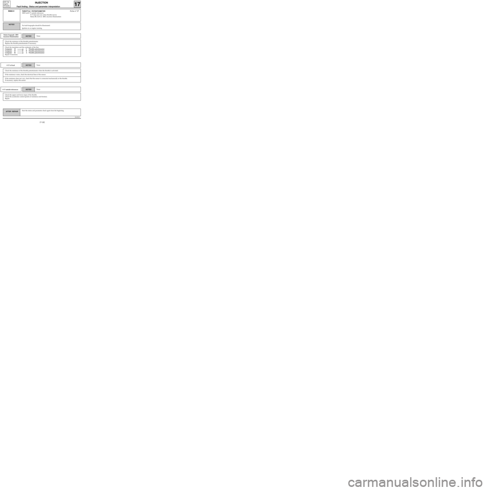
Check the insulation and the continuity of the line:
Computer 19 C Throttle potentiometer
Computer 45 B Throttle potentiometer
Computer 46 A Throttle potentiometer
Repair if necessary.
JSA052.0
INJECTION
Fault finding - Status and parameter interpretation17
D7F 710
engine -
55 tracks
AFTER REPAIRStart the status and parameter check again from the beginning.
DIAG 2THROTTLE POTENTIOMETERFiche n° 27
XR25 aid:# 17 outside tolerances
# 17 does not vary when throttle moves
Status BG 2LH or 2RH, incorrect illumination
No fault bargraphs should be illuminated.
Ignition on or engine running.NOTES
Status bargraph 2RH
incorrect illuminationNoneNOTES
Check the resistance of the throttle potentiometer.
Replace the throttle potentiometer if necessary.
# 17 is fixedNoneNOTES
Check the resistance of the throttle potentiometer when the throttle is activated.
If the resistance varies, check the electrical lines of the sensor.
If the resistance does not vary, check that the sensor is connected mechanically to the throttle.
If necessary, replace the sensor.
# 17 outside tolerancesNoneNOTES
Check the upper and lower stops of the throttle.
Check the accelerator control (points of resistance and friction).
Repair.
17-182
Page 232 of 363
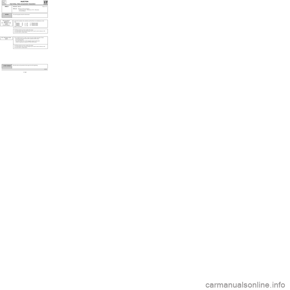
Check the insulation, the continuity and that there is no interference on the
line:
Computer 45 C Pressure sensor
Computer 44 A Pressure sensor
Computer 16 B Pressure sensor
Repair if necessary.
JSA052.0
INJECTION
Fault finding - Status and parameter interpretation17
D7F 710
engine -
55 tracks
AFTER REPAIRStart the status and parameter check again from the beginning.
DIAG 9PRESSURE CIRCUITFiche n° 27
XR25 aid: Ignition on # 01 not coherent
At idle speed # 01 < Minimum or # 01 > Maximum
# 16 not coherent
No fault bargraphs should be illuminated.NOTES
# 01 not coherent
ignition on
# 01 < Minimum at idle
speed
# 16 not coherent
If all these points are correct, replace the sensor.
A vacuum pump with a pressure gauge may be used to check coherence with
# 01 and to show a faulty sensor.
# 01 > Maximum at idle
speedThe manifold pressure is often a sign of incorrect engine operation. Check
- the sealing of the pipe between the manifold and the sensor,
- the valve clearances,
- the canister bleed valve which should be closed at idle speed,
- cylinder compression using the OPTIMA 5800 station.
If all these points are correct, replace the sensor.
A vacuum pump with a pressure gauge may be used to check coherence with
# 01 and to show a faulty sensor.
17-189
Page 233 of 363
JSA052.0
INJECTION
Fault finding - Status and parameter interpretation17
D7F 710
engine -
55 tracks
AFTER REPAIRStart the status and parameter check again from the beginning.
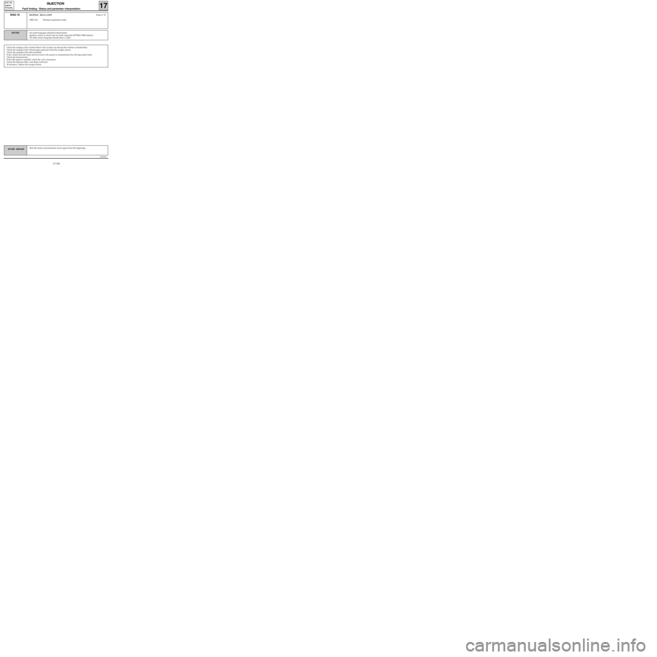
DIAG 10RICHNESS REGULATIONFiche n° 27
XR25 aid: Richness regulation faulty
No fault bargraphs should be illuminated.
Ignition correct (a check may be made using the OPTIMA 5800 station).
No other status bargraph should show a fault.NOTES
Check the sealing of the canister bleed valve (a leak can disrupt the richness considerably).
Check the sealing of the exhaust pipe upstream from the oxygen sensor.
Check the sealing of the inlet manifold.
If the vehicle has only been driven in town, the sensor is contaminated (try driving under load).
Check the fuel pressure.
If the idle speed is unstable, check the valve clearances.
Check the injectors (flow and shape of the jet).
If necessary, replace the oxygen sensor.
17-190
Page 235 of 363
JSA052.0
INJECTION
Fault finding - Status and parameter interpretation17
D7F 710
engine -
55 tracks
AFTER REPAIRStart the status and parameter check again from the beginning.
DIAG 12IMMOBILISERFiche n° 27
XR25 aid : Status BG 3RH, illuminated when ignition switched on
No fault bargraphs should be illuminated.NOTES
Check the insulation and continuity of the wiring for track 37 on the injection computer.
If the fault persists, refer to the immobiliser fault finding.
17-192
Page 239 of 363
JSA052.0
INJECTION
Fault finding - Status and parameter interpretation17
D7F 710
engine -
55 tracks
AFTER REPAIRStart the status and parameter check again from the beginning.
DIAG 15
Cont.Fiche n° 27
No fault bargraphs should be illuminated.
NOTES
NOTES λ > 1.03 at 2500 rpmNone
The oxygen sensor loops correctly at 2500 rpm.
NOTES λ < 0.97
at 2500 rpm.The oxygen sensor does not loop correctly at 2500 rpm, CO >
0.3 % at 2500 rpm.
Check the pressure sensor.
Check the sensor.
Check that an injector is not faulty.
Check there is no leak at the exhaust.
Check that an injector has not seized.
Check the fuel pressure is not too low.
The oxygen sensor does not loop correctly at 2500 rpm.
Check there is not an injection fault.
Check there is not an ignition fault.
Check the sensor is not faulty.
Check the fuel pressure.
17-196