battery RENAULT KANGOO 1997 KC / 1.G Foult Finding - Injection User Guide
[x] Cancel search | Manufacturer: RENAULT, Model Year: 1997, Model line: KANGOO, Model: RENAULT KANGOO 1997 KC / 1.GPages: 363
Page 143 of 363
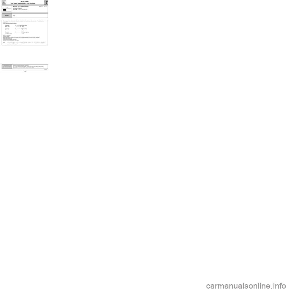
This bargraph only illuminates when the computer feed has been cut (disconnection of the battery, the
computer, ...).
Check the computer feed hygiene:
Computer 18 5 Main relay
Main relay 3 Fuse
Computer 26 2 Main relay
Main relay 1 Fuse
Computer 20 2 Fuel pump relay
Fuel pump relay 1 Fuse
Repair if necessary.
Turn the engine.
Switch the ignition off and wait for the loss of dialogue between the XR25 and the computer.
Switch the ignition on.
Enter dialogue with the computer.
Erase the computer memory using G0**.
NOTE :memorised faults are erased. It would therefore be useful to carry out a road test to check there
are no faults on the injection system.
JSA051.0
INJECTION
Fault finding - Interpretation of XR25 bargraphs17
D7F 710
engine -
35 tracks
Erase the computer memory using G0**.
Try to start the engine. Switch the ignition on, then deal with the other faults.
Remember to carry out a status and parameter check.AFTER REPAIR
Bargraph 13 LH side illuminatedFiche n° 27 side 1/2
MEMORY CIRCUIT
XR25 aid:Loss of computer feed
13
NoneNOTES
17-98
Page 148 of 363
JSA051.0
INJECTION
Fault finding - Status and parameter checks
17
D7F 710
engine -
35 tracks
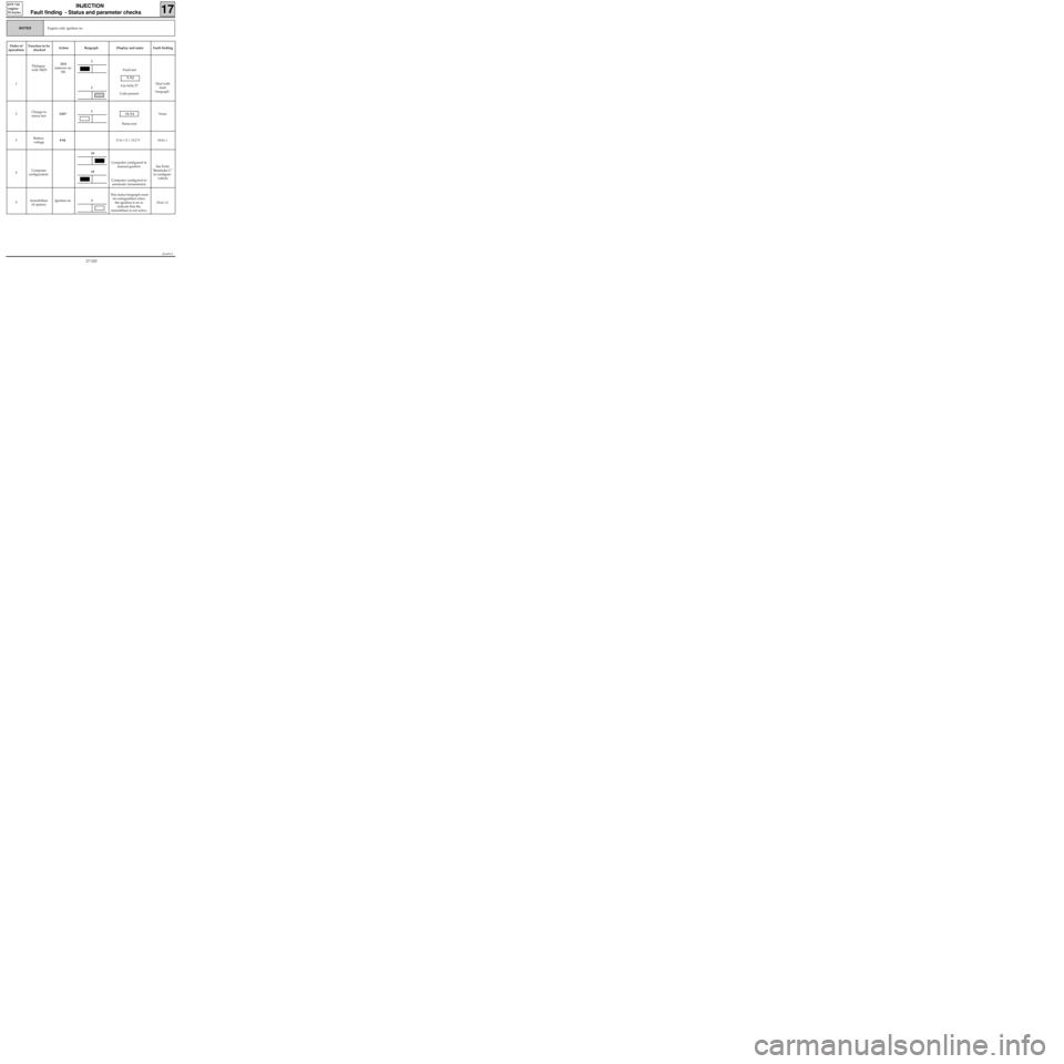
Engine cold, ignition on.NOTES
Order of
operationsFunction to be
checkedAction Bargraph Display and notes Fault finding
1Dialogue
with XR25D13
(selector on
S8)Fault test
9.NJ
Use fiche 27
Code present
Deal with
fault
bargraph
2Change to
status testG01*
10.NJ
Status testNone
3Battery
voltage# 0411.8 < X < 13.2 V
DIAG 1
4Computer
configurationComputer configured to
manual gearbox
Computer configured to
automatic transmissionSee Fiche
"Reminder C"
to configure
vehicle
5Immobiliser
(if option)Ignition onThis status bargraph must
be extinguished when
the ignition is on to
indicate that the
immobiliser is not active.
DIAG 12
1
19
19
1
1
3
17-103
Page 154 of 363
JSA051.0
INJECTION
Fault finding - Status and parameter interpretation17
D7F 710
engine -
35 tracks
AFTER REPAIRStart the status and parameter check again from the beginning.
DIAG 1
Fiche n° 27
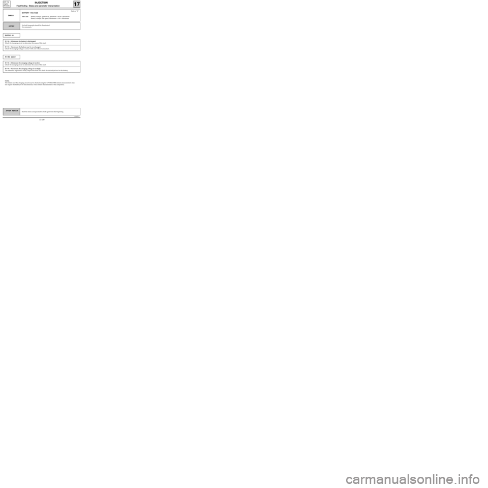
BATTERY VOLTAGE
XR25 aid:Battery voltage, ignition on, Minimum < # 04 < Maximum
Battery voltage, idle speed, Minimum < # 04 < Maximum
No fault bargraphs should be illuminated.
No consumersNOTES
If # 04 < Minimum, the battery is discharged:
Check the charging circuit to determine the cause of this fault.
Ignition on
If # 04 > Maximum, the battery may be overcharged:
Check the charging voltage is correct with and without consumers.
If # 04 < Minimum, the charging voltage is too low:
Check the charging circuit to determine the cause of this fault.
At idle speed
If # 04 > Maximum, the charging voltage is too high:
The alternator regulator is faulty. Repair this fault and check the electrolyte level in the battery.
NOTE:
The battery and the charging circuit may be checked using the OPTIMA 5800 station (measurement does
not require the battery to be disconnected, which retains the memories of the computers).
17-109
Page 183 of 363
JSA051.0
INJECTION
Fault finding - Checking conformity
17
D7F 710
engine -
35 tracks
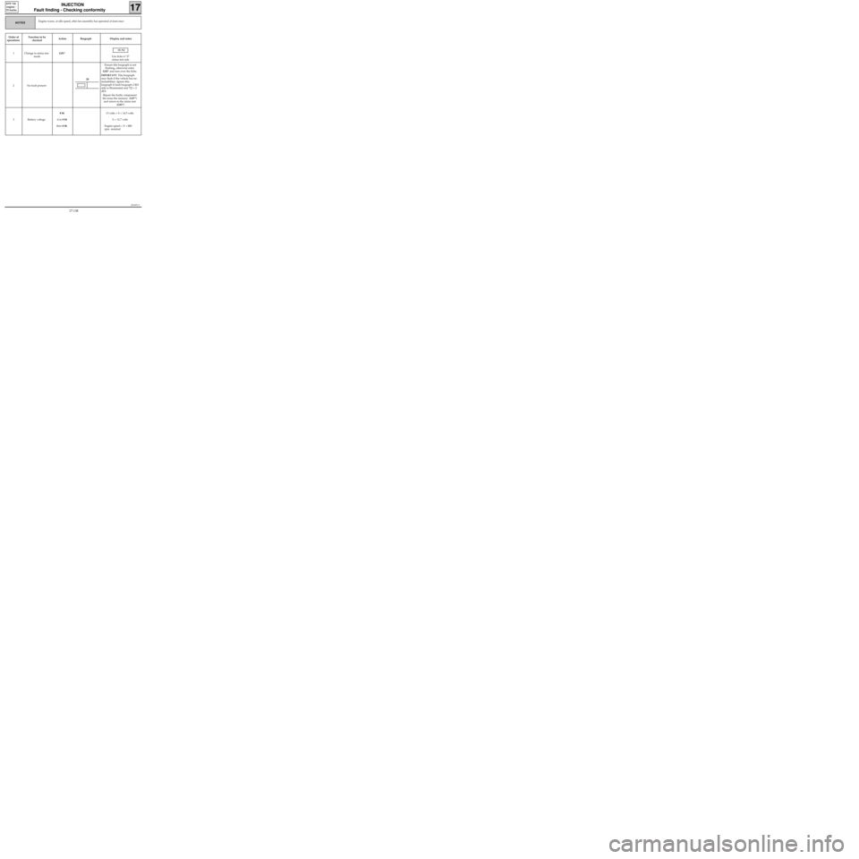
Order of
operationsFunction to be
checkedAction Bargraph Display and notes
1 Change to status test
modeG01*
10.NJ
Use fiche n° 27
status test side
2 No fault presentEnsure this bargraph is not
flashing, otherwise enter
G02* and turn over the fiche.
IMPORTANT: This bargraph
may flash if the vehicle has no
immobiliser. Ignore this
bargraph if fault bargraph 2 RH
side is illuminated and *22 = 2
dEF.
Repair the faulty component
the erase the memory (G0**)
and return to the status test
(G01*)
3 Battery voltage# 04
if in # 04
then # 06 13 volts < X < 14.5 volts
X < 12.7 volts
Engine speed < X < 880
rpm nominal
Engine warm, at idle speed, after fan assembly has operated at least onceNOTES
20
17-138
Page 191 of 363
JSA052.0
INJECTION
Fault finding - Introduction
17
D7F 710
engine -
55 tracks
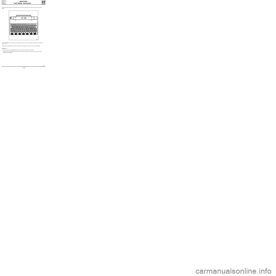
If the information obtained by the XR25 requires electrical continuities to be checked, connect bornier Sus
1228.
Bornier Sus 1228 is a 55 track base with a printed circuit on which are 55 copper coated surfaces, numbered
from 1 to 55.
Using the wiring diagrams, the tracks connecting the components to be tested can be easily identified.
IMPORTANT :
• All tests using bornier Sus 1228 must be carried out with the battery disconnected.
• The bornier is only designed to operate with an ohmmeter. Under no circumstances should 12 Volts be
applied to the test points.
97434S
17-148
Page 213 of 363
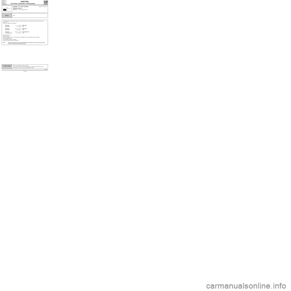
This bargraph only illuminates when the computer feed has been cut (disconnection of the battery, the
computer, ...).
Check the computer feed hygiene:
Computer 1 5 Main relay
Main relay 3 Fuse
Computer 40 2 Main relay
Main relay 1 Fuse
Computer 48 2 Fuel pump relay
Fuel pump relay 1 Fuse
Repair if necessary.
Run the engine.
Switch the ignition off and wait for the loss of dialogue between the XR25 and the computer.
Switch the ignition on.
Enter dialogue with the computer.
Erase the computer memory using G0**.
NOTE :Memorised faults are erased. It would therefore be useful to carry out a road test to check
there are no faults on the injection system.
JSA052.0
INJECTION
Fault finding - Interpretation of XR25 bargraphs17
D7F 710
engine -
55 tracks
Erase the computer memory using G0**.
Try to start the engine. Switch the ignition on, then deal with the other faults.
Remember to carry out a status and parameter check.AFTER REPAIR
Bargraph 13 LH side illuminatedFiche n° 27 side 1/2
MEMORY CIRCUIT
XR25 aid:Loss of computer feed.
13
NoneNOTES
17-170
Page 218 of 363
JSA052.0
INJECTION
Fault finding - Status and parameter checks
17
D7F 710
engine -
55 tracks
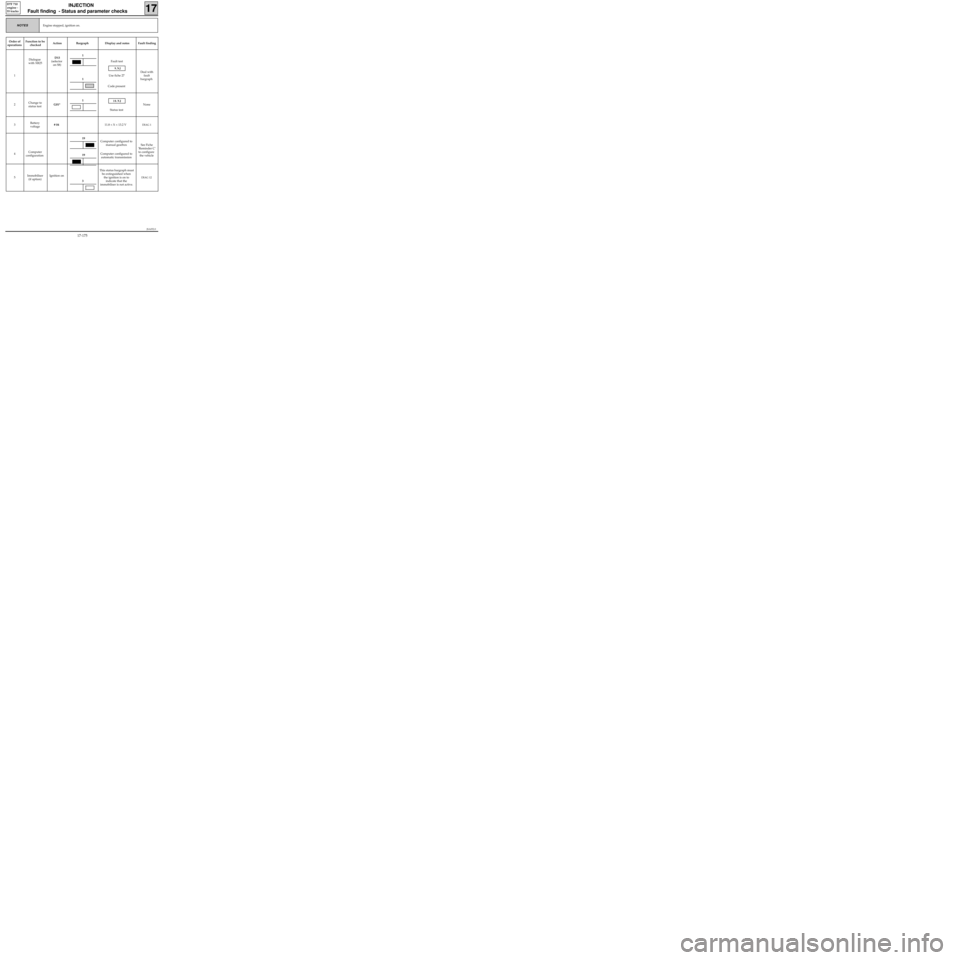
Engine stopped, ignition on.NOTES
Order of
operationsFunction to be
checkedAction Bargraph Display and notes Fault finding
1Dialogue
with XR25D13
(selector
on S8)Fault test
9.NJ
Use fiche 27
Code present
Deal with
fault
bargraph
2Change to
status testG01*
10.NJ
Status testNone
3Battery
voltage# 0411.8 < X < 13.2 V
DIAG 1
4Computer
configurationComputer configured to
manual gearbox
Computer configured to
automatic transmissionSee Fiche
’Reminder C’
to configure
the vehicle
5Immobiliser
(if option)Ignition onThis status bargraph must
be extinguished when
the ignition is on to
indicate that the
immobiliser is not active.
DIAG 12
1
19
19
1
1
3
17-175
Page 224 of 363
JSA052.0
INJECTION
Fault finding - Status and parameter interpretation17
D7F 710
engine -
55 tracks
AFTER REPAIRStart the status and parameter check again from the beginning.
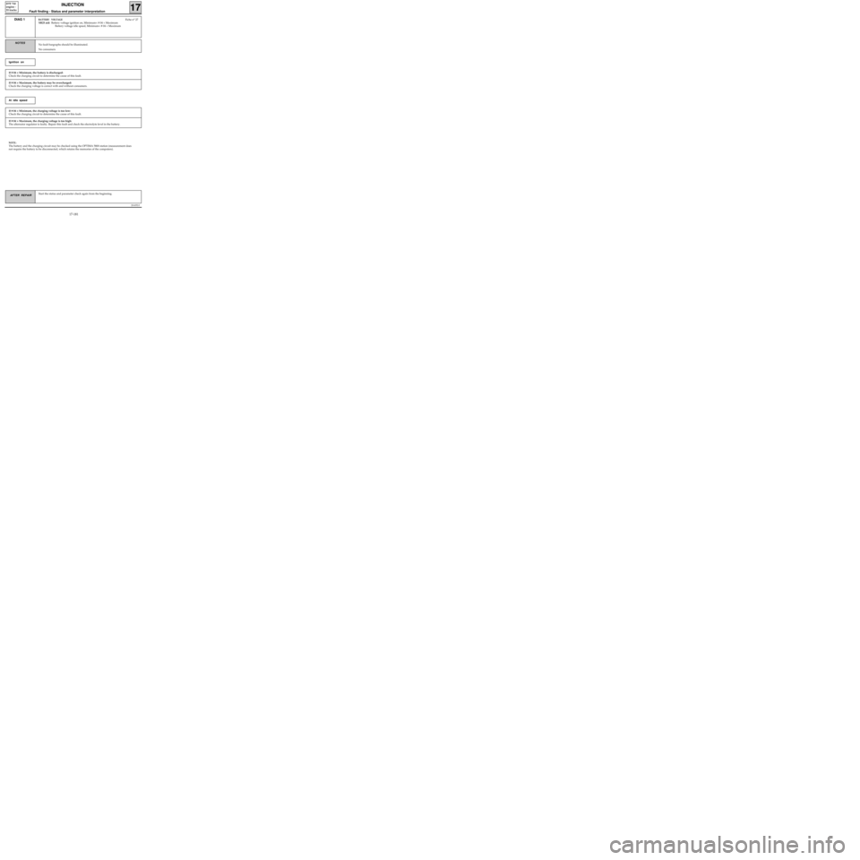
DIAG 1BATTERY VOLTAGEFiche n° 27
XR25 aid: Battery voltage ignition on, Minimum< # 04 < Maximum
Battery voltage idle speed, Minimum< # 04 < Maximum
No fault bargraphs should be illuminated.
No consumersNOTES
If # 04 < Minimum, the battery is discharged:
Check the charging circuit to determine the cause of this fault.
Ignition on
If # 04 > Maximum, the battery may be overcharged:
Check the charging voltage is correct with and without consumers.
If # 04 < Minimum, the charging voltage is too low:
Check the charging circuit to determine the cause of this fault.
At idle speed
If # 04 > Maximum, the charging voltage is too high:
The alternator regulator is faulty. Repair this fault and check the electrolyte level in the battery.
NOTE:
The battery and the charging circuit may be checked using the OPTIMA 5800 station (measurement does
not require the battery to be disconnected, which retains the memories of the computers).
17-181
Page 254 of 363
JSA051.0
INJECTION
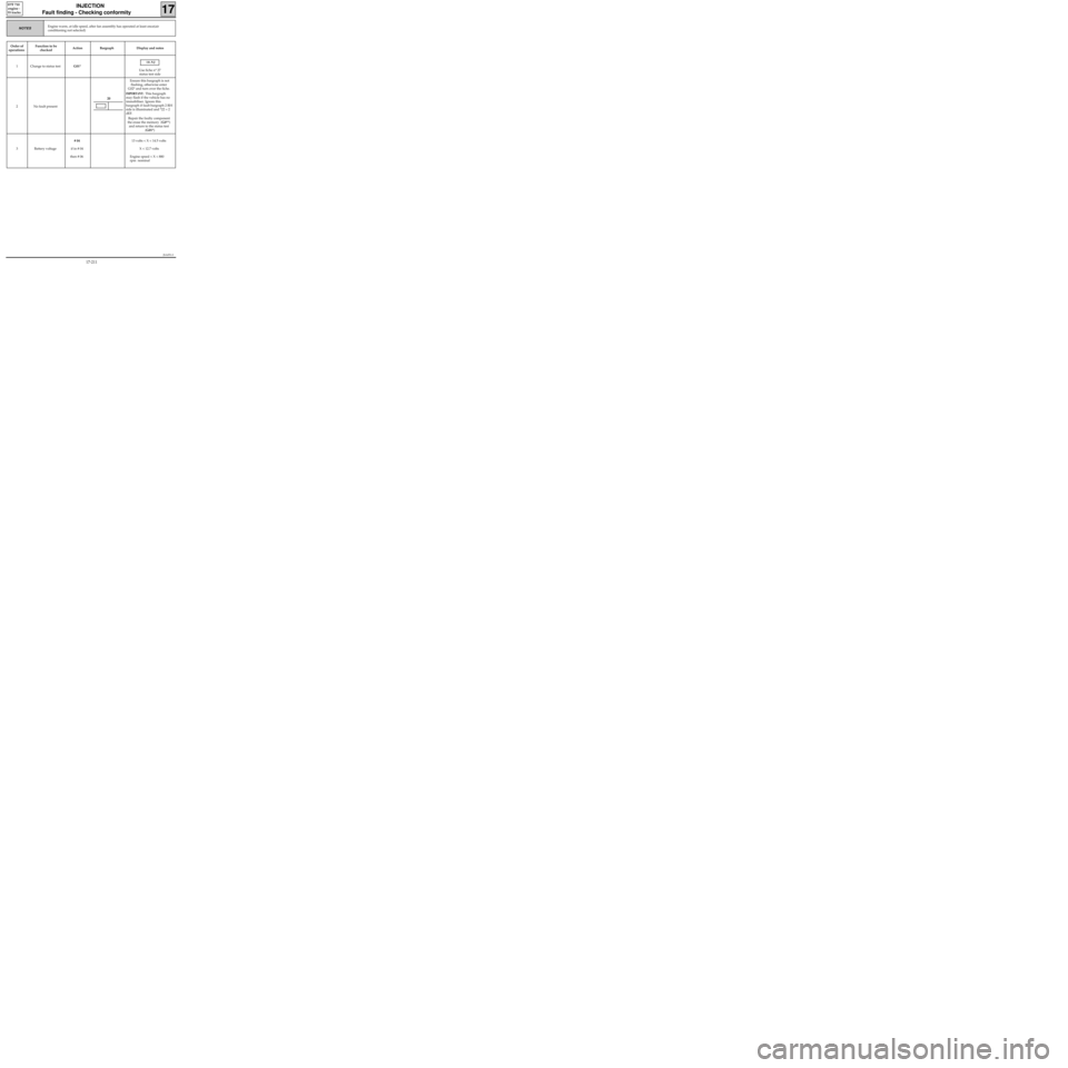
Fault finding - Checking conformity
17
D7F 710
engine -
55 tracks
Order of
operationsFunction to be
checkedAction Bargraph Display and notes
1 Change to status testG01*
10.NJ
Use fiche n° 27
status test side
2 No fault presentEnsure this bargraph is not
flashing, otherwise enter
G02* and turn over the fiche.
IMPORTANT: This bargraph
may flash if the vehicle has no
immobiliser. Ignore this
bargraph if fault bargraph 2 RH
side is illuminated and *22 = 2
dEF.
Repair the faulty component
the erase the memory (G0**)
and return to the status test
(G01*)
3 Battery voltage# 04
if in # 04
then # 06 13 volts < X < 14.5 volts
X < 12.7 volts
Engine speed < X < 880
rpm nominal
Engine warm, at idle speed, after fan assembly has operated at least once(air
conditioning not selected)NOTES
20
17-211
Page 265 of 363
B76531.0
ELECTRONICALLY CONTROLLED HYDRAULIC SYSTEMS
Fault finding - Interpretation of XR25 bargraphs
38
ABS BOSCH
5.3
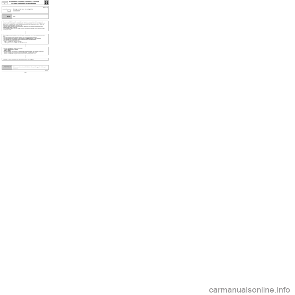
Bargraph 1, right hand side extinguished
Code present
1
None. NOTES
Fiche n° 53
Check that the XR25 kit is not the cause of the fault by trying to communicate with the computer of
another vehicle. If the XR25 kit is not at fault and it will not communicate with any other computer in the
same vehicle, it is possible that a faulty computer is corrupting fault finding lines K and L . Locate this
computer by disconnecting the lines one by one.
Check that the ISO interface is correctly in position S8 and that you are using the most recent XR25
cassette and the correct access code.
Check the battery voltage and carry out the necessary operations to obtain the correct voltage(9.4Volts<
U battery<17.4Volts)
Check the presence and condition of the ABS fuse on the connection unit of the passenger compartment
(10A).
Check the connection of the computer connector and the condition of its connection.
Check the connection and condition of the connection at the R36 dashboard / ABS connection.
Check the ABS earth wires (tighten the two earth screws above the ABS assembly).
Check that the computer is correctly fed :
-earth on track 19 of the 31 track connector,
-+ after ignition feed on track 15 of the 31track connector.
Check that the diagnostic socket is correctly fed :
-+ before ignition feed on track 16,
-earth on track 5.
Check the continuity and insulation of the lines in the diagnostic socket / ABS computer connection:
- between track 12 of the computer connector and track 15 of the diagnostic socket,
- between track 11 of the computer connector and track 7 of the diagnostic socket.
If dialogue is still not established after these tests, replace the ABS computer.,
When communication is established, deal with any fault bargraphs which may be
illuminated. AFTER REPAIR
38-4