battery RENAULT KANGOO 1997 KC / 1.G Foult Finding - Injection Workshop Manual
[x] Cancel search | Manufacturer: RENAULT, Model Year: 1997, Model line: KANGOO, Model: RENAULT KANGOO 1997 KC / 1.GPages: 363
Page 9 of 363
DPCF01 1.0
LUCAS DIESEL INJECTION
Fault finding - Interpretation of XR25 bargraphs13
AFTER REPAIR
Fiche n° 60 1/2
Bargraph 1 RH extinguished
Code present
1
Use bornier Elé. 1332 for any operations on the computer connector.NOTES
When communication is established, deal with any fault bargraphs which may be
illuminated.
Ensure that the XR25 is not the cause of the fault by trying to communicate with the computer on ano-
ther vehicle. If the XR25 is not the cause of the fault and dialogue is not established with another compu-
ter on the same vehicle, a faulty computer may be causing interference on the K and L fault finding lines.
Disconnect connections successively to determine which computer is at fault.
Check the ISO selector is on position S8, that you are using the latest XR25 cassette and the correct access
code (D34).
Check the battery voltage and carry out any necessary operations to ensure the correct voltage (U battery
> 10.5 volts).
Check the 15 Amp fuses on the engine connection unit have not blown (positions 3 and 4).
Check the connection and condition of the connections on the computer connector and the connection
R67 engine / dashboard.
Check the computer is correctly fed:
- Earth on track 2 of the computer connector (check the condition and tightness of the engine earth
strap and the engine earth MH near to the gearbox housing).
- + after ignition feed on track 1 of the computer connector.
Check the diagnostic socket is correctly fed:
- Earth on track 5.
- + before ignition feed on track 16.
Check and ensure the continuity and insulation of the lines in the connection diagnostic socket/
computer:
- Between track 10 of the computer connector and track 15 of the diagnostic socket.
- Between track 13 of the computer connector and track 7 of the diagnostic socket.
If fault finding is not established after these operations, replace the computer (consult the "Aid" section
for this operation).
13-5
Page 28 of 363
DPCF01 1.0
LUCAS DIESEL INJECTION
Fault finding - Interpretation of XR25 bargraphs13
AFTER REPAIRErase the computer memory (G0**), switch the ignition off, then carry out a road
test.
Finish the operation by checking using the XR25.
Bargraph 12 LH illuminated
Battery voltage
XR25 aid:*12 :1.dEF : Battery voltage low
2.dEF : Battery voltage too high
12
Carry out a complete check of the charging circuit using the Optima 5800 dia-
gnostic station.NOTES
Carry out the operations required to ensure correct voltage feed to the computer:
8 volts < correct voltage< 16 volts.
- Check the battery charge.
- Check the charging circuit.
- Check the tightness and condition of the battery terminals.
- Check the computer earth.
Ensure the presence of + after ignition feed on track 1 of the computer connector.
Fiche n° 60 1/2
13-24
Page 38 of 363
DPCF01 1.0
LUCAS DIESEL INJECTION
Fault finding - Checking conformity
13
Order of
operationsFunction to check Action Bargraph Display and notes
1 Change to status testG01* 7. dlE
Use fiche n° 60
status test side
2 No faultsEnsure this bargraph is not
flashing, otherwise enter
G02* and turn the fiche over.
Repair the faulty component
then erase the memory (G0**)
and return to status testing
(G01*)
3 Battery voltage#04 13 volts < X < 14.5 volts
Engine warm at idle speed after at least one operation of the engine cooling fan
assembly (air conditioning not selected).NOTES
20
13-34
Page 42 of 363
DPCF01 1.0
LUCAS DIESEL INJECTION
Fault finding - Fault charts
13
AFTER REPAIR
Use bornier Elé. 1332 for any operations on the computer connector.NOTES
Chart 1NO DIALOGUE FROM THE COMPUTER TO THE XR25.
Ensure that the XR25 is not the cause of the fault by trying to communicate with the computer on ano-
ther vehicle. If the XR25 is not the cause of the fault and dialogue is not established with another compu-
ter on the same vehicle, a faulty computer may be causing interference on the K and L fault finding lines.
Disconnect connections successively to determine which computer is at fault.
Check the ISO selector is on position S8, that you are using the latest XR25 cassette and the correct access
code (D34).
Check the battery voltage and carry out any necessary operations to ensure the correct voltage (U battery
> 10.5 volts).
Carry out a road test then check using the XR25.
Deal with any illuminated fault bargraphs.
Check the 15 Amp fuses on the engine connection unit have not blown (positions 3 and 4).
Check the connection and condition of the connections on the computer connector and the connection
R67 engine / dashboard.
Check the computer is correctly fed:
- Earth on track 2 of the computer connector (check the condition and tightness of the engine earth
strap and the engine earth on the gearbox housing).
- + after ignition feed on track 1 of the computer connector.
Check the diagnostic socket is correctly fed:
- Earth on track 5.
- + before ignition feed on track 16.
Check and ensure the continuity and insulation of the lines in the connection diagnostic socket/
computer:
- Between track 10 of the computer connector and track 15 of the diagnostic socket.
- Between track 13 of the computer connector and track 7 of the diagnostic socket.
If fault finding is not established after these operations, replace the computer (consult the "Aid" section
for this operation).
13-38
Page 50 of 363
JF5111.0
INJECTION
Fault finding - Introduction
17
E7J 780
engine
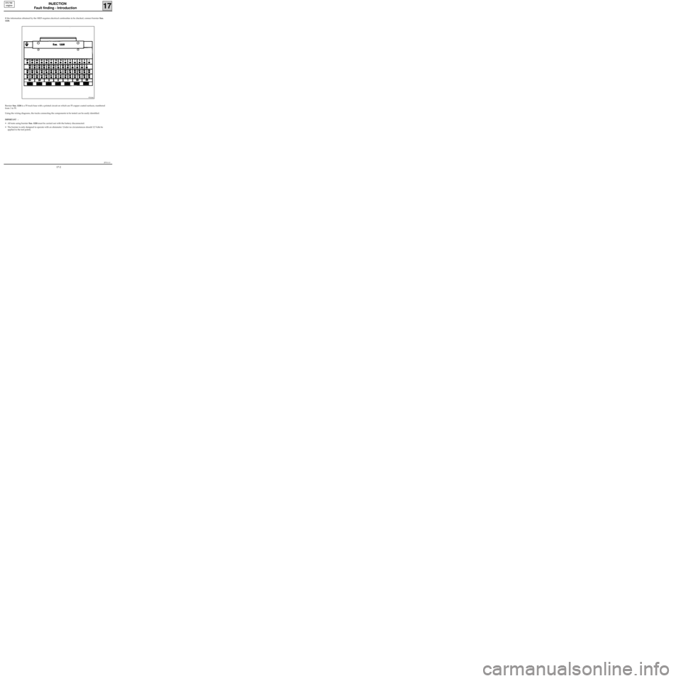
If the information obtained by the XR25 requires electrical continuities to be checked, connect bornier Sus.
1228.
Bornier Sus. 1228 is a 55 track base with a printed circuit on which are 55 copper coated surfaces, numbered
from 1 to 55.
Using the wiring diagrams, the tracks connecting the components to be tested can be easily identified.
IMPORTANT :
• All tests using bornier Sus. 1228 must be carried out with the battery disconnected.
• The bornier is only designed to operate with an ohmmeter. Under no circumstances should 12 Volts be
applied to the test points.
97434S
17-2
Page 71 of 363
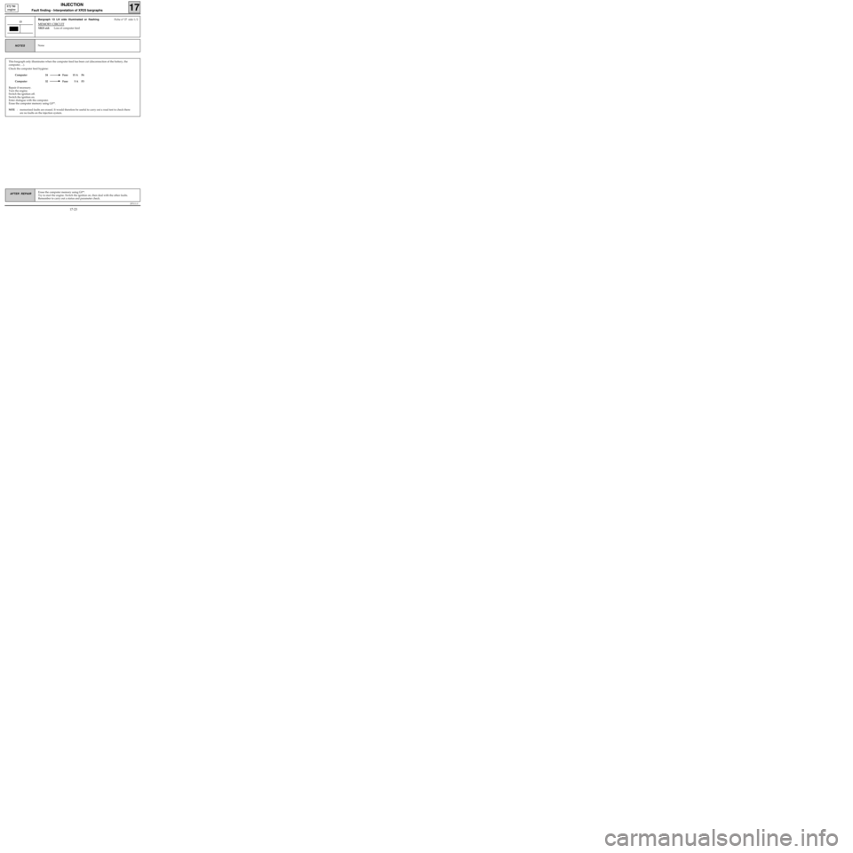
This bargraph only illuminates when the computer feed has been cut (disconnection of the battery, the
computer, ...).
Check the computer feed hygiene:
Computer 24 Fuse 15 A F6
Computer 32 Fuse 5 A F3
Repair if necessary.
Turn the engine.
Switch the ignition off.
Switch the ignition on.
Enter dialogue with the computer.
Erase the computer memory using G0**.
NOTE : memorised faults are erased. It would therefore be useful to carry out a road test to check there
are no faults on the injection system.
JF5111.0
INJECTION
Fault finding - Interpretation of XR25 bargraphs17
E7J 780
engine
Erase the computer memory using G0**.
Try to start the engine. Switch the ignition on, then deal with the other faults.
Remember to carry out a status and parameter check.AFTER REPAIR
Bargraph 13 LH side illuminated or flashingFiche n° 27 side 1/2
MEMORY CIRCUIT
XR25 aid:Loss of computer feed
13
NoneNOTES
17-23
Page 78 of 363
JF5111.0
INJECTION
Fault finding - Status and parameter checks
17
E7J 780
engine
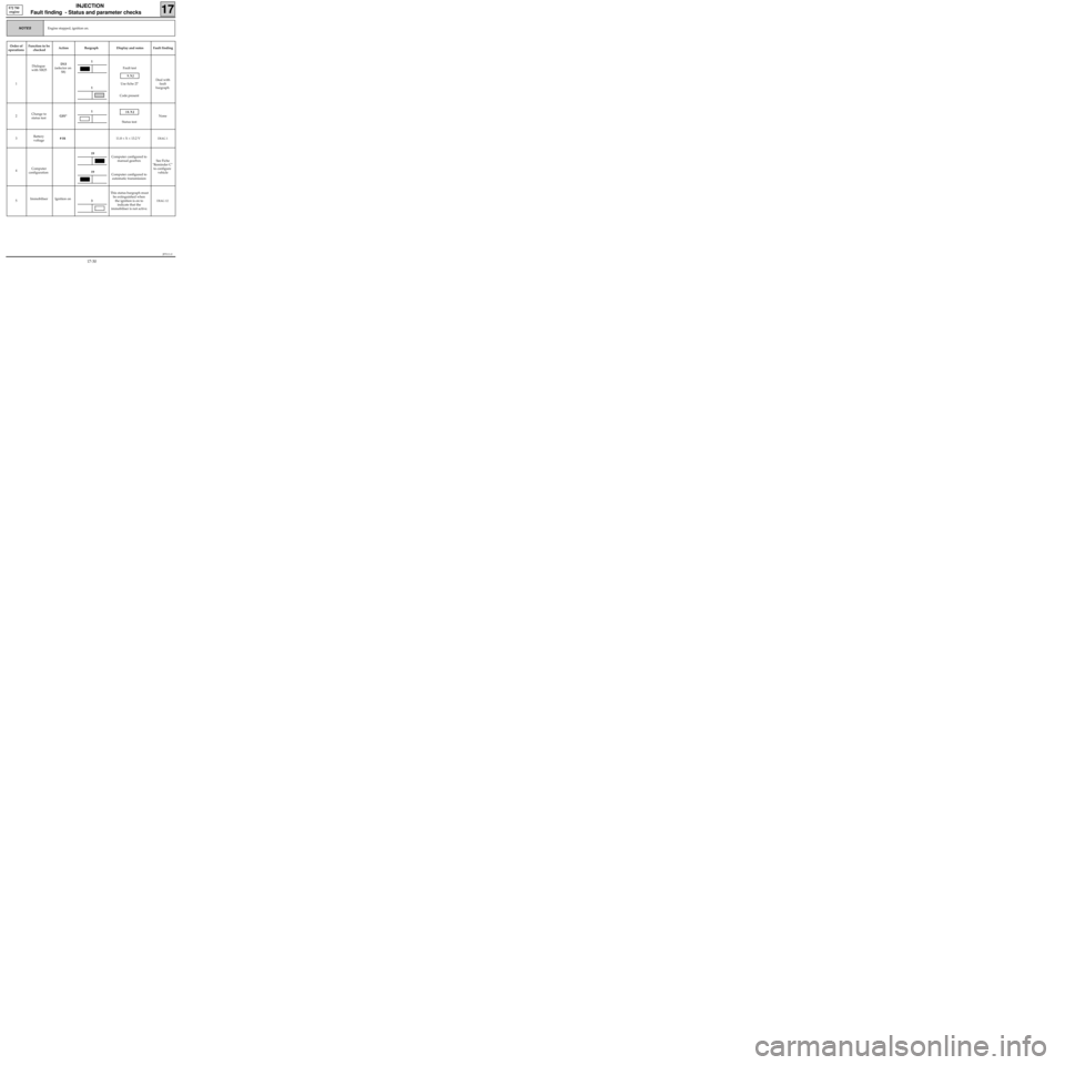
Engine stopped, ignition on.NOTES
Order of
operationsFunction to be
checkedAction Bargraph Display and notes Fault finding
1Dialogue
with XR25D13
(selector on
S8)Fault test
9.NJ
Use fiche 27
Code present
Deal with
fault
bargraph
2Change to
status testG01*
10.NJ
Status testNone
3Battery
voltage# 0411.8 < X < 13.2 V
DIAG 1
4Computer
configurationComputer configured to
manual gearbox
Computer configured to
automatic transmissionSee Fiche
"Reminder C"
to configure
vehicle
5Immobiliser Ignition onThis status bargraph must
be extinguished when
the ignition is on to
indicate that the
immobiliser is not active.
DIAG 12
1
19
19
1
1
3
17-30
Page 84 of 363
JF5111.0
INJECTION
Fault finding - Status and parameter interpretation17
E7J 780
engine
AFTER REPAIRStart the status and parameter check again from the beginning.
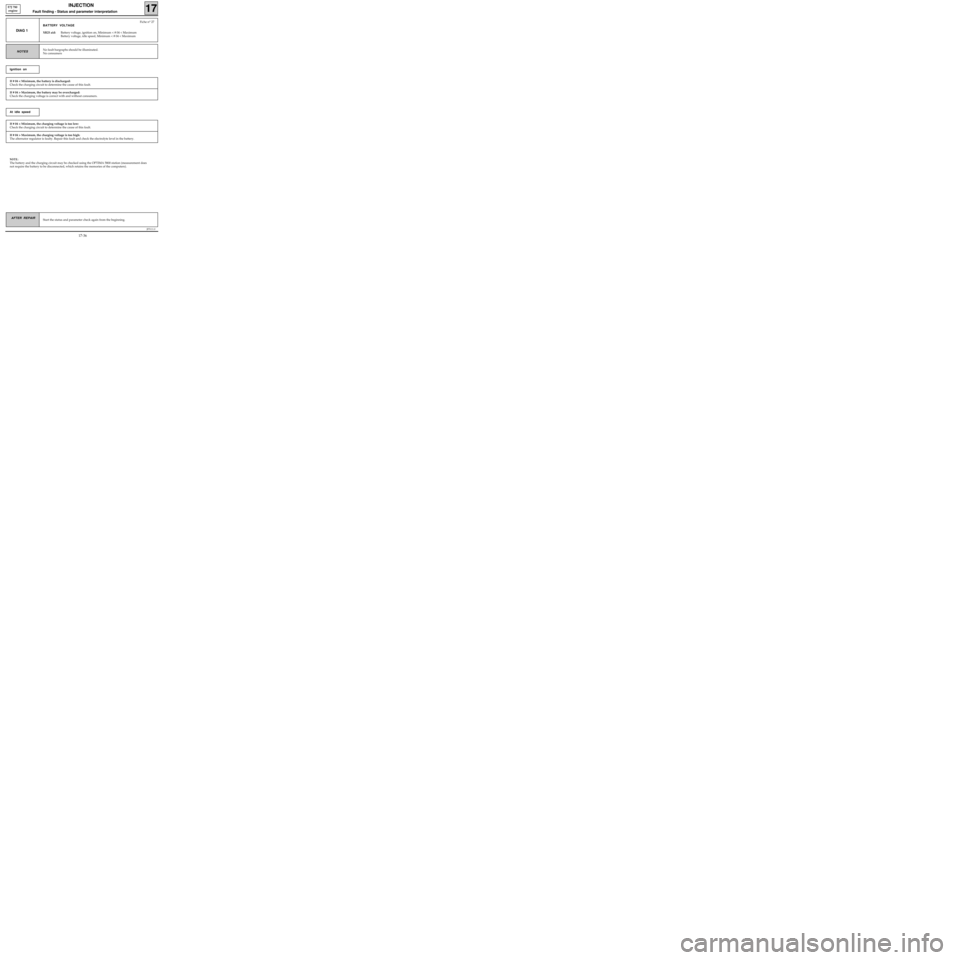
DIAG 1
Fiche n° 27
BATTERY VOLTAGE
XR25 aid:Battery voltage, ignition on, Minimum < # 04 < Maximum
Battery voltage, idle speed, Minimum < # 04 < Maximum
No fault bargraphs should be illuminated.
No consumersNOTES
If # 04 < Minimum, the battery is discharged:
Check the charging circuit to determine the cause of this fault.
Ignition on
If # 04 > Maximum, the battery may be overcharged:
Check the charging voltage is correct with and without consumers.
If # 04 < Minimum, the charging voltage is too low:
Check the charging circuit to determine the cause of this fault.
At idle speed
If # 04 > Maximum, the charging voltage is too high:
The alternator regulator is faulty. Repair this fault and check the electrolyte level in the battery.
NOTE:
The battery and the charging circuit may be checked using the OPTIMA 5800 station (measurement does
not require the battery to be disconnected, which retains the memories of the computers).
17-36
Page 114 of 363
JF5111.0
INJECTION
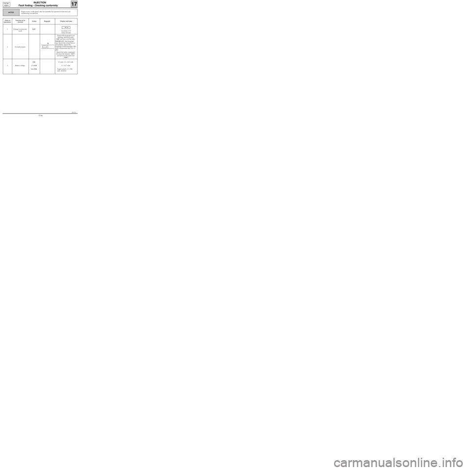
Fault finding - Checking conformity
17
E7J 780
engine
Order of
operationsFunction to be
checkedAction Bargraph Display and notes
1 Change to status test
modeG01*
10.NJ
Use fiche n° 27
status test side
2 No fault presentEnsure this bargraph is not
flashing, otherwise enter
G02* and turn over the fiche.
IMPORTANT: This bargraph
may flash if the vehicle has no
immobiliser. Ignore this
bargraph if fault bargraph 2 RH
side is illuminated and *22 = 2
dEF.
Repair the faulty component
the erase the memory (G0**)
and return to the status test
(G01*)
3 Battery voltage# 04
if in # 04
then # 06 13 volts < X < 14.5 volts
X < 12.7 volts
Engine speed < X < 930
rpm nominal
Engine warm, at idle speed, after fan assembly has operated at least once (air
conditioning not selected).NOTES
20
17-66
Page 121 of 363
JSA051.0
INJECTION
Fault finding - Introduction
17
D7F 710
engine -
35 tracks
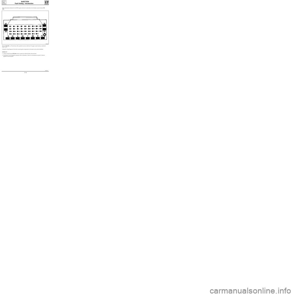
If the information obtained by the XR25 requires electrical continuities to be checked, connect bornier MS
1048.
Bornier MS 1048 is a 35 track base with a printed circuit on which are 35 copper coated surfaces, numbered
from 1 to 35.
Using the wiring diagrams, the tracks connecting the components to be tested can be easily identified.
IMPORTANT :
• All tests using bornier MS 1048 must be carried out with the battery disconnected.
• The bornier is only designed to operate with an ohmmeter. Under no circumstances should 12 Volts be
applied to the test points.
89024S3
17-76