ECO mode RENAULT KANGOO 1997 KC / 1.G Foult Finding - Injection Workshop Manual
[x] Cancel search | Manufacturer: RENAULT, Model Year: 1997, Model line: KANGOO, Model: RENAULT KANGOO 1997 KC / 1.GPages: 363
Page 39 of 363
DPCF01 1.0
LUCAS DIESEL INJECTION
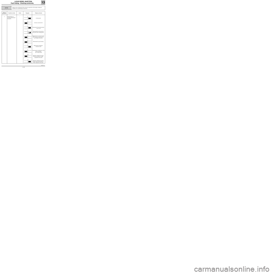
Fault finding - Checking conformity
13
Engine warm at idle speed after at least one operation of the engine cooling fan
assembly (air conditioning not selected).NOTES
Order of
operationsFunction to check Action Bargraph Display and notes
4 Interpretation of
normally illuminated
bargraphs
-
Code present
Advance corrector fed
Illuminated if fast idle solenoid
valve is fed
Illuminated for 40 seconds at
idle speed after starting phase
Illuminated if command mode
G0** has been used since the
last dialogue took place
Illuminated for post heating
Illuminated if altimetric
corrector is fed
Illuminated if vehicle has a PAS
pump assembly
(AC version only)
Injection computer may give
load lever position to other
computers (not used)
Injection computer may give
engine speed information to
other computers (not used)1
2
2
3
4
5
6
6
11
11
13-35
Page 268 of 363
B76531.0
ELECTRONICALLY CONTROLLED HYDRAULIC SYSTEMS
Fault finding - Interpretation of XR25 bargraphs
38
ABS BOSCH
5.3
Erase computer memory(GO**).
Carry out a road test followed by a check with the XR25 kit.AFTER REPAIR
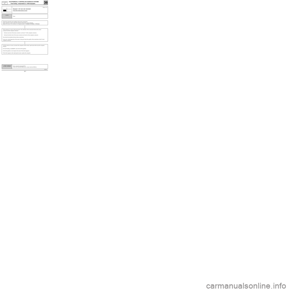
Bargraph 6 left hand side illuminated
Front left wheel sensor circuit
6
None.
NOTES
Fiche n° 53
If the resistance is correct, check and ensure the continuity of the connection between the sensor
connector and the computer connector:
- between one track of the sensor connector and track 7 of the computer connector,
- between the other track of the sensor connector and track 6 of the computer connector.
Also check the insulation between these connections.
Carry out a visual inspection of the sensor wiring and check the quality of the connection on the 31 track
computer connector.
If all the checks are correct, reconnect the computer and the wheel speed sensor then erase the computer
memory.
Exit fault finding mode(G13*) and switch off the ignition.
Switch the ignition on and replace the sensor if the fault reappears.
If the fault reappears after replacing the sensor, replace the computer.
Check the connection and condition of the sensor connections.
If the connector is correct, check the resistance of the sensor at its connector..
Replace the sensor if its resistance is not approximately 1.6 Kohms (1,6 Kohms ± 320 ohms).
38-7
Page 269 of 363
B76531.0
ELECTRONICALLY CONTROLLED HYDRAULIC SYSTEMS
Fault finding - Interpretation of XR25 bargraphs
38
ABS BOSCH
5.3
Erase computer memory(GO**).
Carry out a road test followed by a check with the XR25 kit.AFTER REPAIR
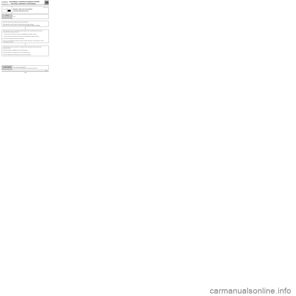
Bargraph 6 Right hand side illuminated
Front right wheel sensor circuit
6
None.
NOTES
Fiche n° 53
If the resistance is correct , check and ensure the continuity of the connections between the sensor
connector and the computer connector :
- between one track of the sensor connector and track 3 of the computer connector,
- between the other track of the sensor connector and track 5 of the computer connector.
Also check the insulation between these connections.
Carry out a visual inspection of the sensor wiring and check the quality of the connections on the 31
track computer connector.
If all the checks are correct, reconnect the computer and the wheel speed sensor, then erase the
computer memory.
Exit the fault finding mode(G13*) and switch off the ignition.
Switch the ignition on and replace the sensor if the fault reappears .
If the fault reappears after replacing the sensor, replace the computer.
Check the connection and condition of the sensor connections.
If the connector is correct, check the resistance of the sensor at its connector.
Replace the sensor if its resistance is not approximately 1.6 Kohms (1.6 Kohms ± 320 ohms).
38-8
Page 270 of 363
B76531.0
ELECTRONICALLY CONTROLLED HYDRAULIC SYSTEMS
Fault finding - Interpretation of XR25 bargraphs
38
ABS BOSCH
5.3
Erase computer memory(GO**).
Carry out a road test followed by a check with the XR25 kit.AFTER REPAIR
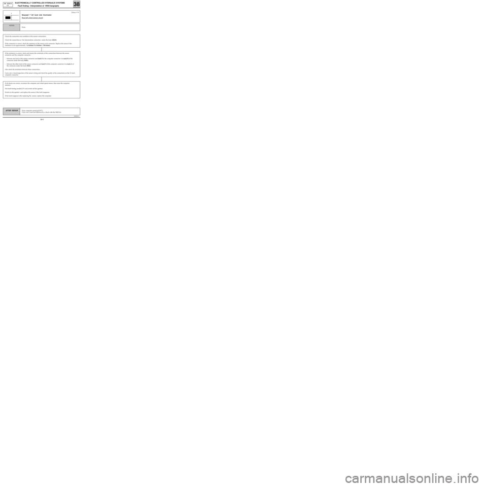
Bargraph 7 left hand side illuminated
Rear left wheel sensor circuit
7
None.
NOTES
Fiche n° 53
If all checks are correct, reconnect the computer and wheel speed sensor, then erase the computer
memory.
Exit fault finding mode(G13*) and switch off the ignition.
Switch on the ignition and replace the sensor if the fault reappears.
If the fault reappears after replacing the sensor, replace the computer.
Check the connection and condition of the sensor connections.
Check the connections at the intermediate connection under the body (R101).
If the connector is correct, check the resistance of the sensor at its connector. Replace the sensor if the
resistance is not approximately 1.6 Kohms (1.6 Kohms ± 320 ohms).
If the resistance is correct, check and ensure the continuity of the connections between the sensor
connector and the computer connector :
- between one track of the sensor connector and track 8 of the computer connector (via track B of the
connector under the body R101),
- between the other track of the sensor connector and track 9 of the computer connector (via track A of
the connector under the body R101).
Also check the insulation between these connections.
Carry out a visual inspection of the sensor wiring and check the quality of the connections on the 31 track
computer connector.
38-9
Page 271 of 363
B76531.0
ELECTRONICALLY CONTROLLED HYDRAULIC SYSTEMS
Fault finding - Interpretation of XR25 bargraphs
38
ABS BOSCH
5.3
Erase computer memory(GO**).
Carry out a road test followed by a check with the XR25 kit.AFTER REPAIR
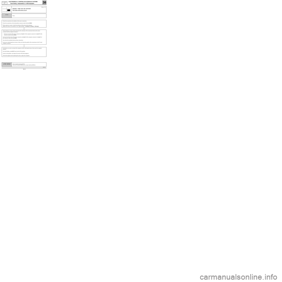
Bargraph 7 Right hand side illuminated
Rear right wheel sensor circuit
7
None.
NOTES
Fiche n° 53
If all checks are correct, reconnect the computer and the wheel speed sensor, then erase the computer
memory.
Exit fault finding mode(G13*) and switch off the ignition.
Switch on the ignition and replace the sensor if the fault reappears.
If the fault reappears after replacing the sensor, replace the computer.
Check the connection and condition of the sensor connections.
Check the connections at the intermediate connector under the body (R101).
If the connector is correct , check the resistance of the sensor at its connector.
Replace the sensor if its resistance is not approximately 1.6 Kohms (1.6 Kohms ± 320 ohms).
If the resistance is correct, check and ensure the continuity of the connections between the sensor
connector and the computer connector :
- between one track of the sensor connector and track 1 of the computer connector (via track D of the
connector under the body R101),
-between the other track of the sensor connector and track 2 of the computer connector (via track C of
the connector under the body R101).
Also check the insulation between these connections.
Carry out a visual inspection of sensor wiring and check the quality of the connections on the 31 track
computer connector.
38-10
Page 272 of 363
B76531.0
ELECTRONICALLY CONTROLLED HYDRAULIC SYSTEMS
Fault finding - Interpretation of XR25 bargraphs
38
ABS BOSCH
5.3
Erase computer memory(GO**).
Carry out a road test followed by a check with the XR25 kit.AFTER REPAIR
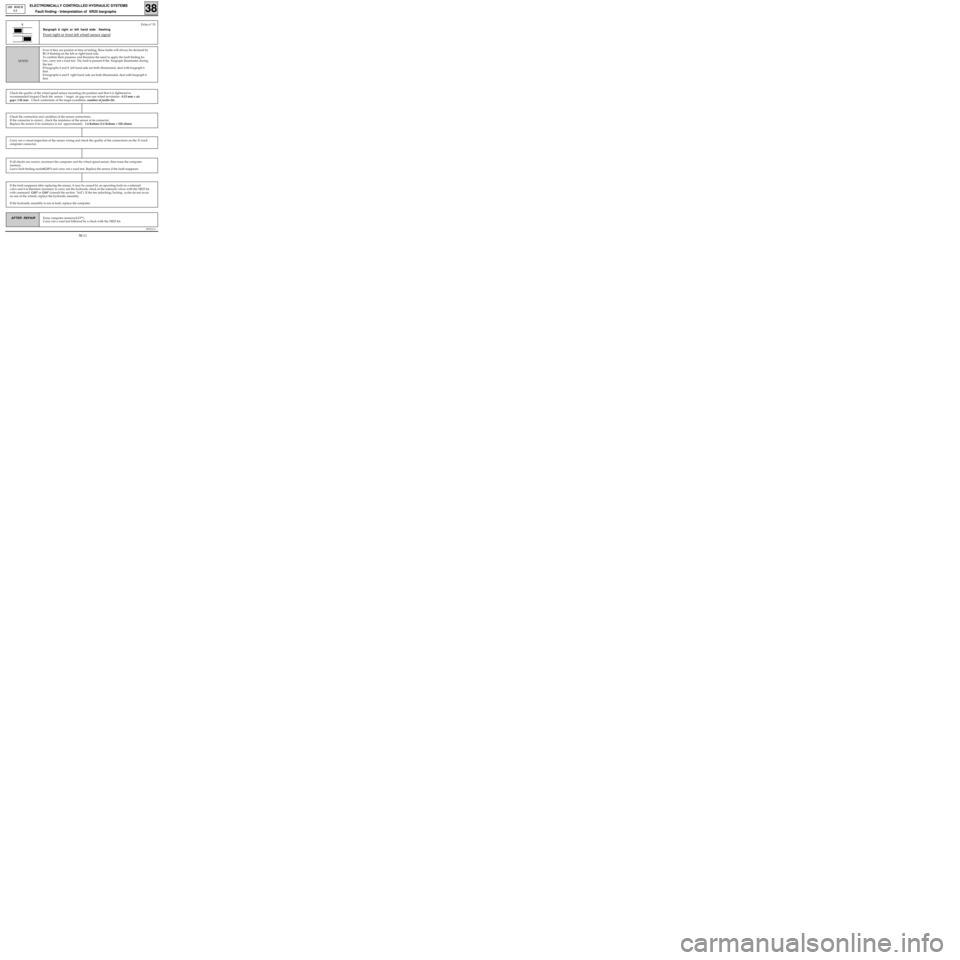
Bargraph 8 right or left hand side flashing
Front right or front left wheel sensor signal
Even if they are present at time of testing, these faults will always be declared by
BG 8 flashing on the left or right hand side.
To confirm their presence and therefore the need to apply the fault finding be-
low, carry out a road test. The fault is present if the bargraph illuminates during
the test.
If bargraphs 6 and 8 left hand side are both illuminated, deal with bargraph 6
first.
If bargraphs 6 and 8 right hand side are both illuminated, deal with bargraph 6
first.
NOTES
Fiche n° 53 8
Check the quality of the wheel speed sensor mounting (its position and that it is tightened to
recommended torque).Check the sensor / target air gap over one wheel revolution : 0.13 mm < air
gap< 1.96 mm. Check conformity of the target (condition, number of
teeth=26)
Carry out a visual inspection of the sensor wiring and check the quality of the connections on the 31 track
computer connector.
If all checks are correct, reconnect the computer and the wheel speed sensor, then erase the computer
memory.
Leave fault finding mode(G13*) and carry out a road test. Replace the sensor if the fault reappears.
If the fault reappears after replacing the sensor, it may be caused by an operating fault on a solenoid
valve and it is therefore necessary to carry out the hydraulic check of the solenoid valves with the XR25 kit
with command G03* or G04* (consult the section "Aid"). If the ten unlocking/locking cycles do not occur
on one of the wheels, replace the hydraulic assembly.
If the hydraulic assembly is not at fault, replace the computer.
Check the connection and condition of the sensor connections.
If the connector is correct , check the resistance of the sensor at its connector.
Replace the sensor if its resistance is not approximately 1.6 Kohms (1.6 Kohms ± 320 ohms).
38-11
Page 273 of 363
B76531.0
ELECTRONICALLY CONTROLLED HYDRAULIC SYSTEMS
Fault finding - Interpretation of XR25 bargraphs
38
ABS BOSCH
5.3
Erase computer memory(GO**).
Carry out a road test followed by a check with the XR25 kit.AFTER REPAIR
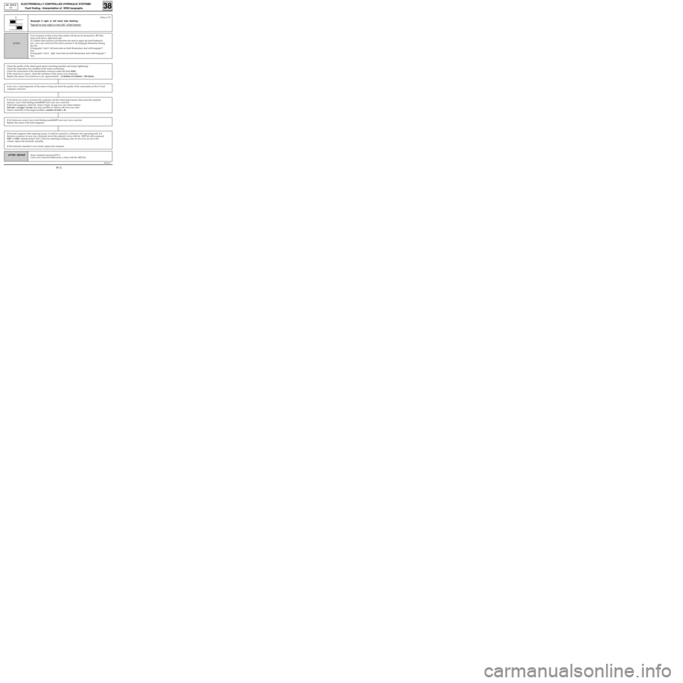
Bargraph 9 right or left hand side flashing
Signals to rear right or rear left wheel sensor
Even if present at time of test, these faults will always be declared by BG9 flas-
hing on the left or right hand side.
To confirm their presence and therefore the need to apply the fault finding be-
low, carry out a road test.The fault is present if the bargraph illuminates during
the test.
If bargraphs 7 and 9 left hand side are both illuminated, deal with bargraph 7
first.
If bargraphs 7 and 9 right hand side are both illuminated, deal with bargraph 7
first.
NOTES
Fiche n° 53 9
Check the quality of the wheel speed sensor mounting (position and torque tightening).
Check the connection and condition of the sensor connections.
Check the connections at the intermediate connector under the body R101.
If the connector is correct , check the resistance of the sensor at its connector.
Replace the sensor if its resistance is not approximately 1.6 Kohms (1.6 Kohms ± 320 ohms).
Carry out a visual inspection of the sensor wiring and check the quality of the connections on the 31 track
computer connector.
If all checks are correct, reconnect the computer and the wheel speed sensor, then erase the computer
memory. Leave fault finding mode(G13*) and carry out a road test.
If the fault reappears, check the sensor/target air gap over one wheel rotation :
0.03 mm < air gap< 2.4 mm (test only possible on vehicle with 4 bar rear axle).
Check conformity of the target:condition, number of teeth = 26.
If the fault reappears after replacing sensor, it could be caused by a solenoid valve operating fault. It is
therefore necessary to carry out a hydraulic test of the solenoid valves with the XR25 kit with command
G05* or G06* (consult section"Aid"). If the ten unlocking/locking cycles do not occur on one of the
wheels, replace the hydraulic assembly.
If the hydraulic assembly is not at fault, replace the computer.
If all checks are correct, leave fault finding mode(G13*) and carry out a road test.
Replace the sensor if the fault reappears.
38-12
Page 274 of 363
B76531.0
ELECTRONICALLY CONTROLLED HYDRAULIC SYSTEMS
Fault finding - Interpretation of XR25 bargraphs
38
ABS BOSCH
5.3
Erase computer memory(GO**).
Carry out a road test followed by a check with the XR25 kit.AFTER REPAIR
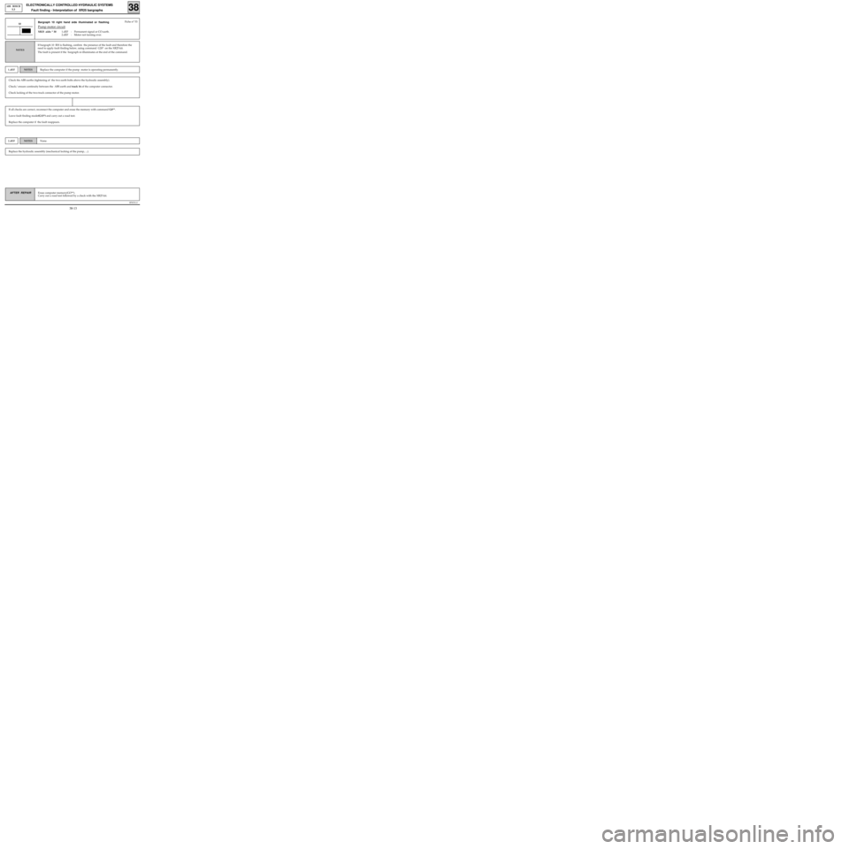
Bargraph 10 right hand side illuminated or flashing
Pump motor circuit
XR25 aids: * 301.dEF : Permanent signal or CO earth.
2.dEF : Motor not turning over.
10
If bargraph 10 RH is flashing, confirm the presence of the fault and therefore the
need to apply fault finding below, using command G20* on the XR25 kit.
The fault is present if the bargraph re-illuminates at the end of the command.
NOTES
Fiche n° 53
If all checks are correct, reconnect the computer and erase the memory with command G0**.
Leave fault finding mode(G13*) and carry out a road test.
Replace the computer if the fault reappears.
Check the ABS earths (tightening of the two earth bolts above the hydraulic assembly).
Check/ ensure continuity between the ABS earth and track 16 of the computer connector.
Check locking of the two-track connector of the pump motor.
1.dEFNOTESReplace the computer if the pump motor is operating permanently.
Replace the hydraulic assembly (mechanical locking of the pump, ...).
2.dEFNOTESNone.
38-13
Page 275 of 363
B76531.0
ELECTRONICALLY CONTROLLED HYDRAULIC SYSTEMS
Fault finding - Interpretation of XR25 bargraphs
38
ABS BOSCH
5.3
Erase computer memory(GO**).
Carry out a road test followed by a check with the XR25 kit.AFTER REPAIR
Bargraph 11 left hand side illuminated
Solenoid valve power supply fault
11Fiche n° 53
If all the checks are correct, reconnect the computer then erase its memory with command G0**.
Leave fault finding mode(G13*) and carry out a road test. Replace the computer if the fault reappears.
Carry out operations necessary for obtaining correct voltage between tracks 19 and 17/18 of the 31-track
ABS computer connector (9.4 volts < correct voltage < 17.4 volts) :
- Check tightness and condition of battery terminals.
- Check the 60A fuse in the engine connection unit (white base).
- Ensure continuity between the 60A fuse and tracks 17 and 18 of the computer connector.
- Check the ABS earths (tightening of the two earth bolts above the hydraulic assembly).
- Check/ ensure continuity between the ABS earth and track 19 of the computer connector.
None.
NOTES
38-14
Page 291 of 363
B76531.0
ELECTRONICALLY CONTROLLED HYDRAULIC SYSTEM
Fault finding - Fault chart 38
ABS BOSCH
5.3
AFTER REPAIR Carry out a road test, then a check with the XR25 kit.
BRAKE PEDAL TRAVEL EXTENDED FOLLOWING A
REGULATION PHASE
(WITH IRREGULAR PEDAL AT START OF REGULATION)
Fault chart 10
Passage of air from the hydraulic assembly regulation channels to brake circuits.
Bleed the circuits according to the procedure recommended in the Technical Note (use of XR25 command
modes. These command modes are described in the section "Aid").
After the operation, carry out a road test with ABS regulation.
Only consult this section after a complete check with the XR25 kit.NOTES
If the fault persists, carry out the preceding operation once or twice more.
If customer complaint is particularly serious and bleeding brings about no improvement, replace the
hydraulic assembly.
38-30