engine RENAULT KANGOO 1997 KC / 1.G Foult Finding - Injection Workshop Manual
[x] Cancel search | Manufacturer: RENAULT, Model Year: 1997, Model line: KANGOO, Model: RENAULT KANGOO 1997 KC / 1.GPages: 363
Page 233 of 363
JSA052.0
INJECTION
Fault finding - Status and parameter interpretation17
D7F 710
engine -
55 tracks
AFTER REPAIRStart the status and parameter check again from the beginning.
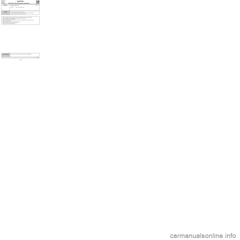
DIAG 10RICHNESS REGULATIONFiche n° 27
XR25 aid: Richness regulation faulty
No fault bargraphs should be illuminated.
Ignition correct (a check may be made using the OPTIMA 5800 station).
No other status bargraph should show a fault.NOTES
Check the sealing of the canister bleed valve (a leak can disrupt the richness considerably).
Check the sealing of the exhaust pipe upstream from the oxygen sensor.
Check the sealing of the inlet manifold.
If the vehicle has only been driven in town, the sensor is contaminated (try driving under load).
Check the fuel pressure.
If the idle speed is unstable, check the valve clearances.
Check the injectors (flow and shape of the jet).
If necessary, replace the oxygen sensor.
17-190
Page 234 of 363
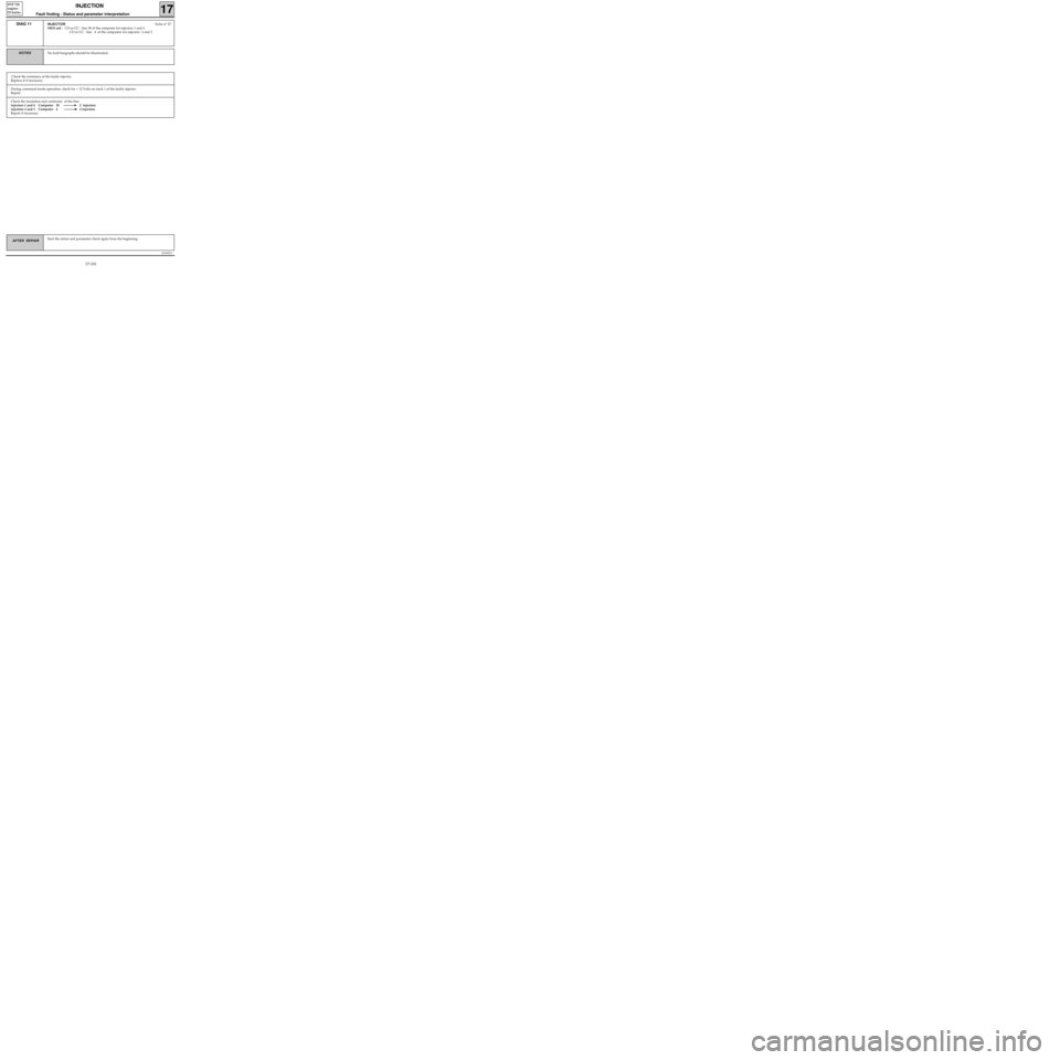
Check the insulation and continuity of the line:
injectors 1 and 4 Computer 30 2 injectors
injectors 2 and 3 Computer 4 2 injectors
Repair if necessary.
JSA052.0
INJECTION
Fault finding - Status and parameter interpretation17
D7F 710
engine -
55 tracks
AFTER REPAIRStart the status and parameter check again from the beginning.
DIAG 11INJECTORFiche n° 27
XR25 aid : CO or CC - line 30 of the computer for injectors 1 and 4
CO or CC - line 4 of the computers for injectors 2 and 3
No fault bargraphs should be illuminated.NOTES
Check the resistance of the faulty injector.
Replace it if necessary.
During command mode operation, check for + 12 Volts on track 1 of the faulty injector.
Repair.
17-191
Page 235 of 363
JSA052.0
INJECTION
Fault finding - Status and parameter interpretation17
D7F 710
engine -
55 tracks
AFTER REPAIRStart the status and parameter check again from the beginning.
DIAG 12IMMOBILISERFiche n° 27
XR25 aid : Status BG 3RH, illuminated when ignition switched on
No fault bargraphs should be illuminated.NOTES
Check the insulation and continuity of the wiring for track 37 on the injection computer.
If the fault persists, refer to the immobiliser fault finding.
17-192
Page 236 of 363
if the value read is incoherent:
- Check that the sensor is correctly mounted and fed:
• +12 V on A1
• Earth on B2
- Check the insulation, continuity and that there is no interference resistance on the line:
Computer 12 B1 vehicle speed sensor
Repair.
JSA052.0
INJECTION
Fault finding - Status and parameter interpretation17
D7F 710
engine -
55 tracks
AFTER REPAIRStart the status and parameter check again from the beginning.
DIAG 13
Fiche n° 27
VEHICLE SPEED
XR25 aid: # 18 = Speed read on speedometer in km/h
No fault bargraphs should be illuminated. Check with a road test.NOTES
The fault persists! Replace the speed sensor.
17-193
Page 237 of 363
JSA052.0
INJECTION
Fault finding - Status and parameter interpretation17
D7F 710
engine -
55 tracks
AFTER REPAIRStart the status and parameter check again from the beginning.
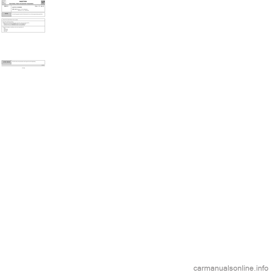
DIAG 14Fiche n° 27 side 2/2
ADAPTIVE RICHNESS
XR25 aid:Minimum < # 30 < Maximum
Minimum < # 31 < Maximum
No fault bargraphs should be illuminated.Carry out the programming operations.NOTES
Ensure the canister bleed valve is sealed.
Erase the computer memory.
Engine warm , running at idle speed, check the values for # 30 and # 31.
-If # 30 or # 31 is at a MAXIMUM, there is not enough fuel.
- If # 30 or # 31 is at a MINIMUM, there is too much fuel.
Ensure the hygiene, cleanliness and correct operation of :
- filter
- fuel pump
- fuel circuit
- fuel tank.
17-194
Page 238 of 363
JSA052.0
INJECTION
Fault finding - Status and parameter interpretation17
D7F 710
engine -
55 tracks
AFTER REPAIRStart the status and parameter check again from the beginning.
NOTES
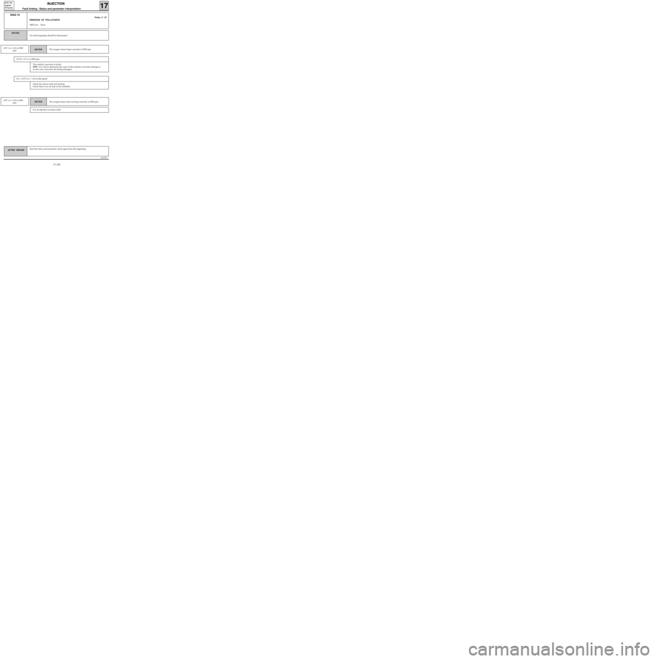
DIAG 15
Fiche n° 27
EMISSION OF POLLUTANTS
XR25 aid:
None
No fault bargraphs should be illuminated.
NOTES
0.97 ≤ λ ≤ 1.03 at 2500
rpmThe oxygen sensor loops correctly at 2500 rpm.
If CO > 0.3 % at 2500 rpm
NOTES 0.97 ≤ λ ≤ 1.03 at 2500
rpmThe oxygen sensor does not loop correctly at 2500 rpm.
It is an injection or sensor fault.
The catalytic converter is faulty.
NOTE : it is vital to determine the cause of the catalytic converter damage to
avoid a new converter also being damaged.
If λ < 0.97 or λ > 1.03 at idle speed
Check the sensor earth and heating.
Check there is no air leak at the manifold.
17-195
Page 239 of 363
JSA052.0
INJECTION
Fault finding - Status and parameter interpretation17
D7F 710
engine -
55 tracks
AFTER REPAIRStart the status and parameter check again from the beginning.
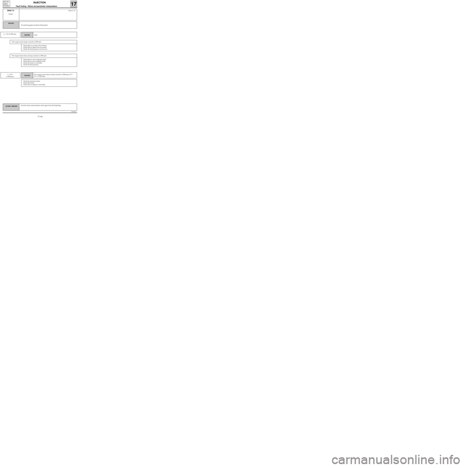
DIAG 15
Cont.Fiche n° 27
No fault bargraphs should be illuminated.
NOTES
NOTES λ > 1.03 at 2500 rpmNone
The oxygen sensor loops correctly at 2500 rpm.
NOTES λ < 0.97
at 2500 rpm.The oxygen sensor does not loop correctly at 2500 rpm, CO >
0.3 % at 2500 rpm.
Check the pressure sensor.
Check the sensor.
Check that an injector is not faulty.
Check there is no leak at the exhaust.
Check that an injector has not seized.
Check the fuel pressure is not too low.
The oxygen sensor does not loop correctly at 2500 rpm.
Check there is not an injection fault.
Check there is not an ignition fault.
Check the sensor is not faulty.
Check the fuel pressure.
17-196
Page 240 of 363
JSA052.0
INJECTION
Fault finding - Status and parameter interpretation17
D7F 710
engine -
55 tracks
AFTER REPAIRStart the status and parameter check again from the beginning.
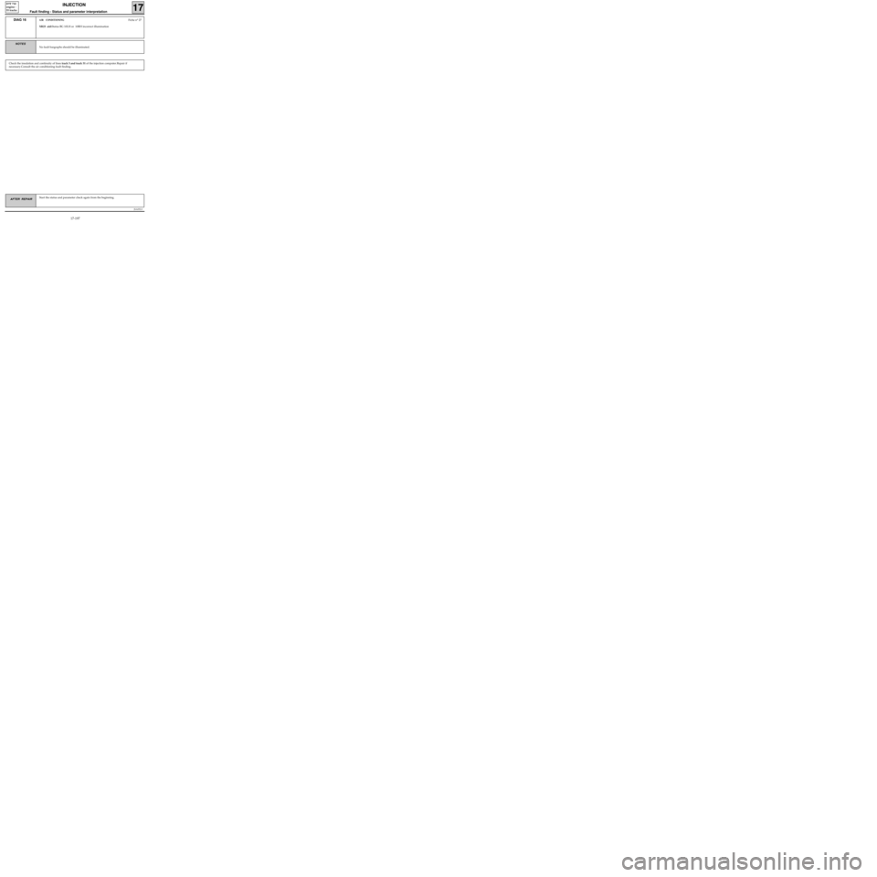
DIAG 16AIR CONDITIONINGFiche n° 27
XR25 aid:Status BG 10LH or 10RH incorrect illumination
No fault bargraphs should be illuminated.
NOTES
Check the insulation and continuity of lines track 5 and track 51 of the injection computer.Repair if
necessary.Consult the air conditioning fault finding.
17-197
Page 241 of 363
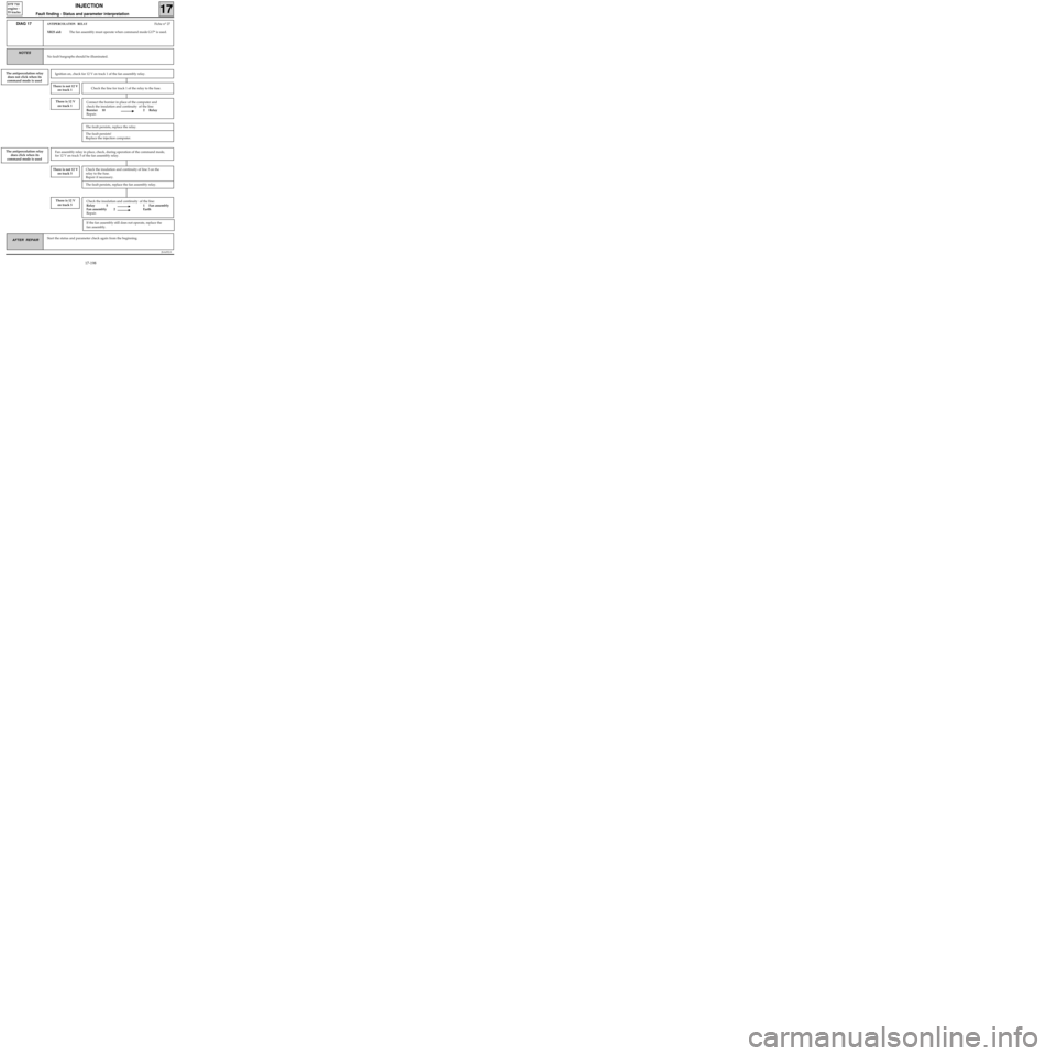
Connect the bornier in place of the computer and
check the insulation and continuity of the line:
Bornier 10 2 Relay
Repair.
Check the insulation and continuity of the line:
Relay 5 1 Fan assembly
Fan assembly 2 Earth
Repair.
JSA052.0
INJECTION
Fault finding - Status and parameter interpretation17
D7F 710
engine -
55 tracks
AFTER REPAIRStart the status and parameter check again from the beginning.
DIAG 17ANTIPERCOLATION RELAYFiche n° 27
XR25 aid:The fan assembly must operate when command mode G17* is used.
No fault bargraphs should be illuminated.
NOTES
The antipercolation relay
does not click when its
command mode is used
There is 12 V
on track 1
Ignition on, check for 12 V on track 1 of the fan assembly relay.
There is not 12 V
on track 1Check the line for track 1 of the relay to the fuse.
The antipercolation relay
does click when its
command mode is usedFan assembly relay in place, check, during operation of the command mode,
for 12 V on track 5 of the fan assembly relay.
There is not 12 V
on track 5Check the insulation and continuity of line 3 on the
relay to the fuse.
Repair if necessary.
The fault persists, replace the fan assembly relay.
There is 12 V
on track 5
If the fan assembly still does not operate, replace the
fan assembly.
The fault persists, replace the relay.
The fault persists!
Replace the injection computer.
17-198
Page 242 of 363
JSA052.0
INJECTION
Fault finding - Status and parameter interpretation17
D7F 710
engine -
55 tracks
AFTER REPAIRStart the status and parameter check again from the beginning.
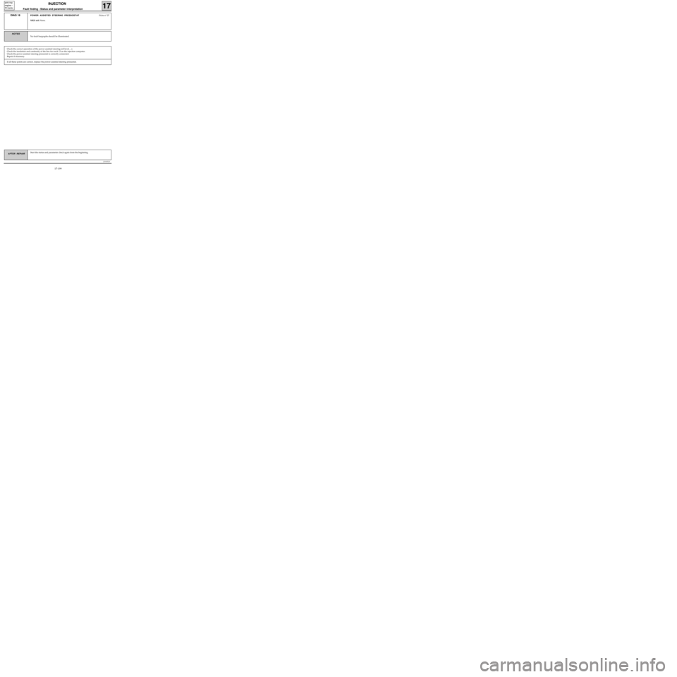
DIAG 18POWER ASSISTED STEERING PRESSOSTATFiche n° 27
XR25 aid :None.
No fault bargraphs should be illuminated.
NOTES
Check the correct operation of the power assisted steering (oil level, ...).
Check the insulation and continuity of the line for track 13 on the injection computer.
Check the power assisted steering pressostat is correctly connected.
Repair if necessary.
If all these points are correct, replace the power assisted steering pressostat.
17-199