engine RENAULT KANGOO 1997 KC / 1.G Foult Finding - Injection Workshop Manual
[x] Cancel search | Manufacturer: RENAULT, Model Year: 1997, Model line: KANGOO, Model: RENAULT KANGOO 1997 KC / 1.GPages: 363
Page 243 of 363
Connect the bornier in place of the computer and check the insulation and continuity of the line:
Computer 43 6 Instrument panel
Repair.
JSA052.0
INJECTION
Fault finding - Status and parameter interpretation17
D7F 710
engine -
55 tracks
AFTER REPAIRStart the status and parameter check again from the beginning.
DIAG 19FAULT WARNING LIGHT CIRCUITFiche n° 27
XR25 aid:None
No fault bargraphs should be illuminated.
NOTES
Check the condition of the warning light and its feed.
Repair if necessary.
17-200
Page 244 of 363
JSA052.0
INJECTION
Fault finding - Customer complaints
17
D7F 710
engine -
55 tracks
Only refer to this customer complaint after a complete check using the XR25.
NOTES
STARTING FAULTS
IDLE SPEED FAULTS
BEHAVIOUR WHILE DRIVING
Chart 1
Chart 2
Chart 3
17-201
Page 245 of 363
JSA052.0
INJECTION
Fault finding - Fault charts
17
D7F 710
engine -
55 tracks
AFTER REPAIR
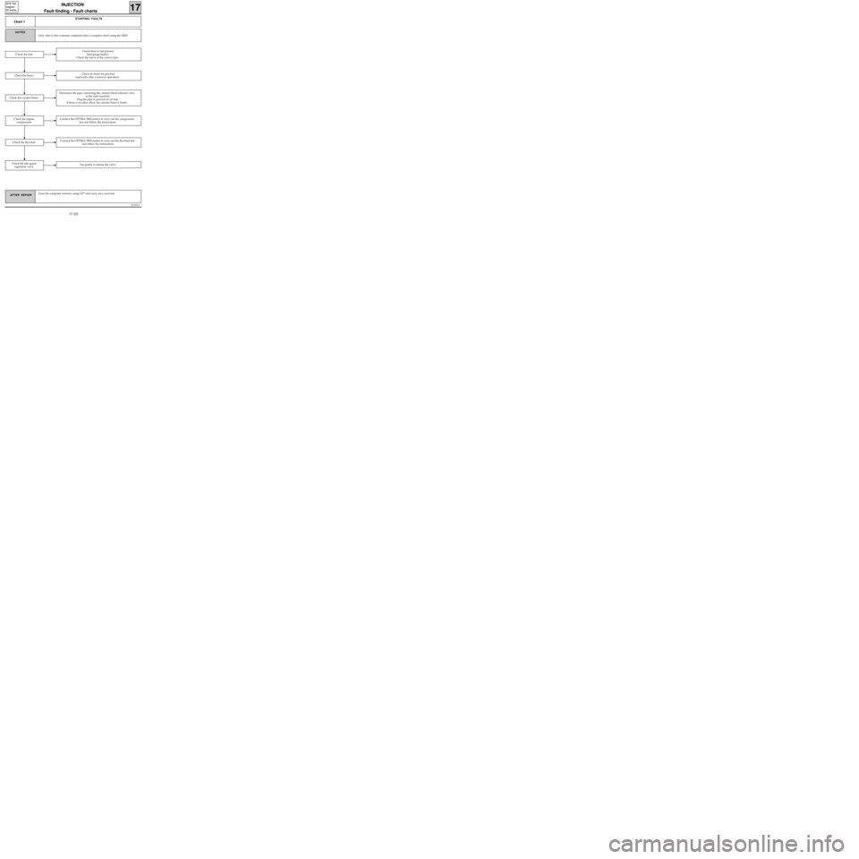
Chart 1
STARTING FAULTS
Only refer to this customer complaint after a complete check using the XR25.
NOTES
Erase the computer memory using G0** and carry out a road test.
Check there is fuel present
(fuel gauge faulty).
Check the fuel is of the correct type.
Check the hosesCheck no hoses are pinched
(especially after a removal operation).
Disconnect the pipe connecting the canister bleed solenoid valve
to the inlet manifold.
Plug the pipe to prevent an air leak.
If there is no other effect, the canister bleed is faulty.
Check the fuel
Connect the OPTIMA 5800 station to carry out the compression
test and follow the instructions.
Connect the OPTIMA 5800 station to carry out the flywheel test
and follow the instructions.
Check the idle speed
regulation valveTap gently to release the valve.
Check the flywheel
Check the engine
compression
Check the canister bleed
17-202
Page 246 of 363
JSA052.0
INJECTION
Fault finding - Fault charts
17
D7F 710
engine -
55 tracks
AFTER REPAIR
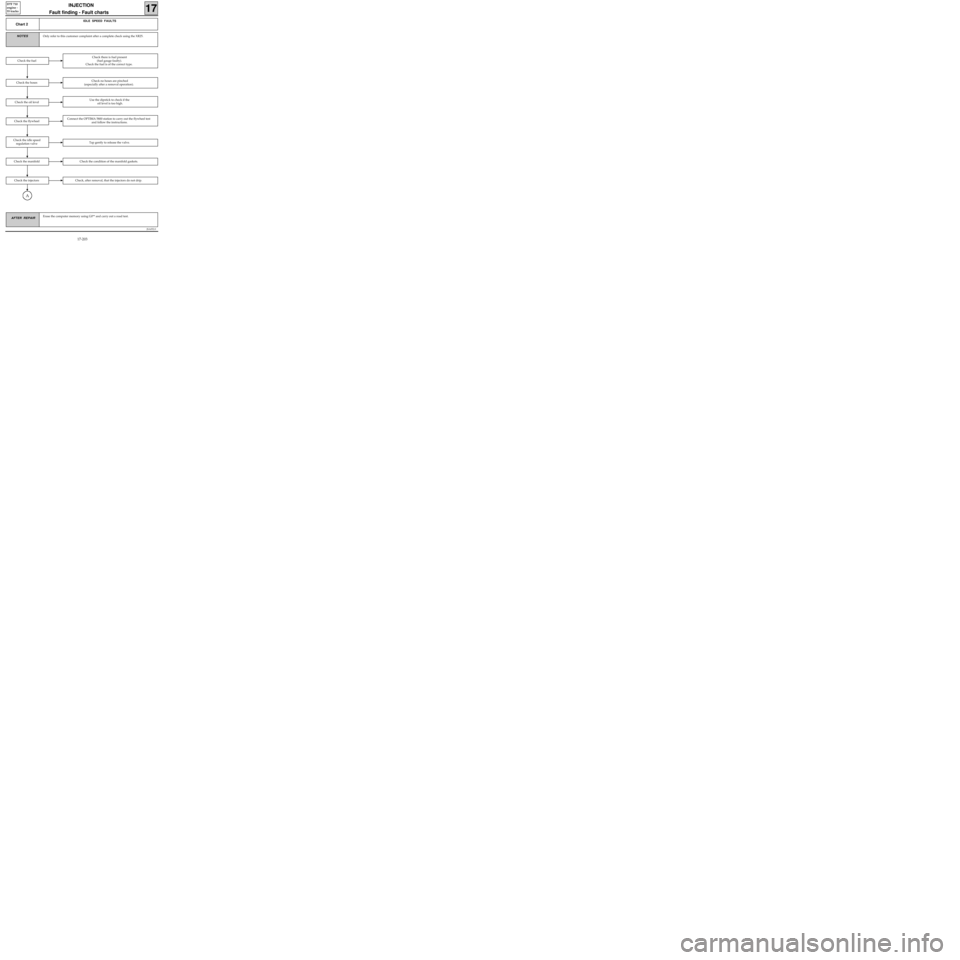
Chart 2
IDLE SPEED FAULTS
Only refer to this customer complaint after a complete check using the XR25.NOTES
Erase the computer memory using G0** and carry out a road test.
Check there is fuel present
(fuel gauge faulty).
Check the fuel is of the correct type.
Check the hosesCheck no hoses are pinched
(especially after a removal operation).
Check the oil levelUse the dipstick to check if the
oil level is too high.
Check the fuel
Check the flywheelConnect the OPTIMA 5800 station to carry out the flywheel test
and follow the instructions.
Check the idle speed
regulation valveTap gently to release the valve.
Check the manifoldCheck the condition of the manifold gaskets.
Check the injectorsCheck, after removal, that the injectors do not drip.
A
17-203
Page 247 of 363
JSA052.0
INJECTION
Fault finding - Fault charts
17
D7F 710
engine -
55 tracks
AFTER REPAIR
Chart 2
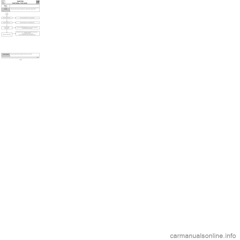
CONT
Only refer to this customer complaint after a complete check using the XR25.NOTES
A
Erase the computer memory using G0** and carry out a road test.
Check the throttle bodyCheck the throttle body is not contaminated.
Check the brake servoCheck the brake servo is not leaking (noise).
Connect the OPTIMA 5800 station to carry out the compression
test and follow the instructions.
Check the canister bleed
Disconnect the pipe connecting the canister bleed solenoid valve
to the inlet manifold.
Plug the pipe to prevent an air leak.
If there is no other effect, the canister bleed is faulty.
Check the engine
compression
17-204
Page 248 of 363
JSA052.0
INJECTION
Fault finding - Fault charts
17
D7F 710
engine -
55 tracks
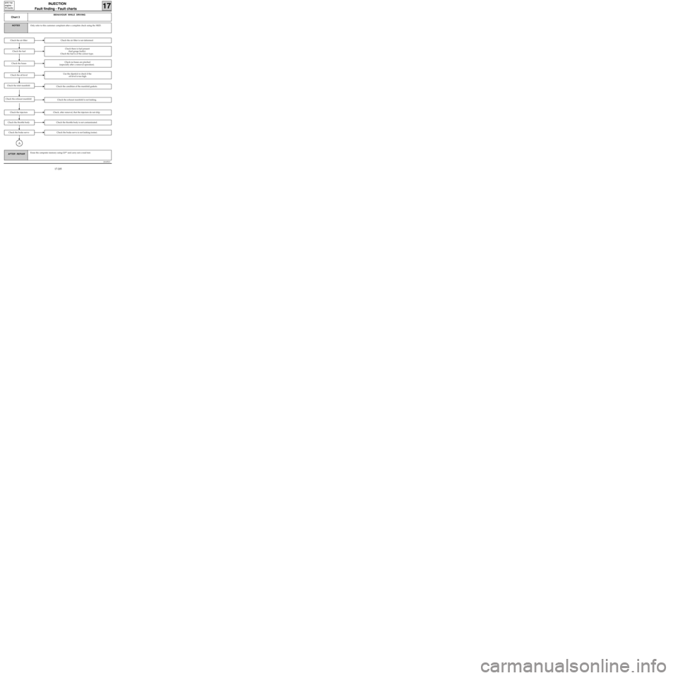
AFTER REPAIRErase the computer memory using G0** and carry out a road test.
Chart 3
BEHAVIOUR WHILE DRIVING
Only refer to this customer complaint after a complete check using the XR25.NOTES
Check the air filter is not deformed.
Check the fuel
Check there is fuel present
(fuel gauge faulty).
Check the fuel is of the correct type.
Check the hosesCheck no hoses are pinched
(especially after a removal operation).
Check the air filter
Check the oil levelUse the dipstick to check if the
oil level is too high.
Check the condition of the manifold gaskets.Check the inlet manifold
Check the exhaust manifold is not leaking.Check the exhaust manifold
Check, after removal, that the injectors do not drip.Check the injectors
Check the throttle body is not contaminated.Check the throttle body
Check the brake servo is not leaking (noise).Check the brake servo
A
17-205
Page 249 of 363
JSA052.0
INJECTION
Fault finding - Fault charts
17
D7F 710
engine -
55 tracks
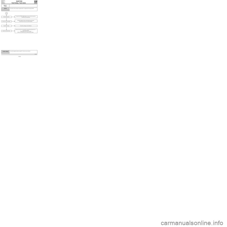
AFTER REPAIRErase the computer memory using G0** and carry out a road test.
Chart 3
CONT
Only refer to this customer complaint after a complete check using the XR25.NOTES
Check the calipers, drums and bearings are not seized.
Check that the tyres are not under inflated.
Check the coolingCheck that cooling is not insufficient.
Check the canister bleed
Disconnect the pipe connecting the canister bleed solenoid valve
to the inlet manifold.
Plug the pipe to prevent an air leak.
If there is no other effect, the canister bleed is faulty..
Check the axle assemblies
A
Connect the OPTIMA 5800 station to carry out the flywheel test
and follow the instructions.Check the flywheel
17-206
Page 250 of 363
JSA052.0
INJECTION Fault finding - Aid
17
D7F 710
engine -
55 tracks
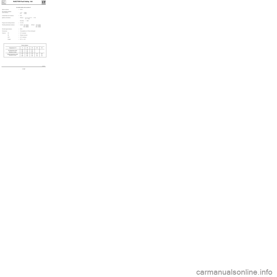
For further details, refer to section 12
Injector resistance = 14.5 Ω
Idle regulation stepping
motor resistance : A - D = 100 Ω
B - C = 100 Ω
Canister bleed valve resistance = 35 Ω
Ignition coil resistance : Primary = 1-4 ; 1-3 ; 2-3 ; 2-4 = 1.5 Ω
3-4 = 0.6 Ω
Secondary = 8 kΩ
Oxygen sensor heating resistance = 3 to 15 Ω
Throttle potentiometer resistance : no load A-B = 1300 Ωfull load A-B = 1300 Ω
A-C= 1360 ΩA-C= 2350 Ω
B-C = 2300 ΩB-C = 1260 Ω
Flywheel signal resistance = 220 Ω
Fuel pressure = 3 bars ignition on/ 2.5 bars at idle speed
Value for: CO = 0.3 % maximum
HC = 100 ppm maximum
CO2 = 14.5 % minimum
Oxygen = 0.97 < λ < 1.03
Sensor resistance
Temperature in °C 0 20 40 80 90
Air temperature sensor
Resistance in ohms5000
to
70001700
to
3300500
to
1550--
Coolant temperature sensor
Resistance in ohms6700
to
80002600
to
30001100
to
1300270
to
300200
to
215
17-207
Page 251 of 363
JSA051.0
INJECTION
Fault finding - Checking conformity
17
D7F 710
engine -
55 tracks
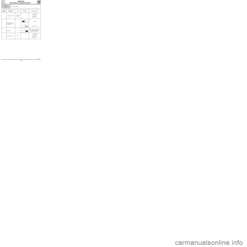
Engine cold, ignition on.NOTES
Order of
operationsFunction to be
checkedAction Bargraph Display and notes
1 Dialogue with XR25D13
(selector on
S8)
9.NJ
Use fiche n° 27
fault test side
2Interpretation of
normally illuminated
bargraphsFault test
Code present
3 ImmobiliserIf the vehicle does not have an
immobiliser, this bargraph
should be illuminated.
4 Change to status testG01*
10.NJ
Use fiche n° 27
status test side
1
1
2
17-208
Page 252 of 363
JSA051.0
INJECTION
Fault finding - Checking conformity
17
D7F 710
engine -
55 tracks
Engine cold, ignition on.NOTES
Order of
operationsFunction to be
checkedAction Bargraph Display and notes
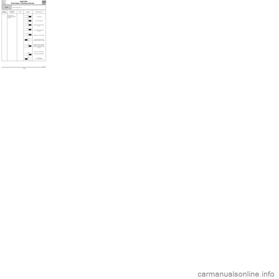
5 Interpretation of
normally illuminated
bargraphsCode present
No load recognition
Illuminated if immobiliser
active
+ after ignition information
received
Locking relay control effective
Always illuminated if air
conditioning option available
Illuminates after erasing the
memory to indicate that the
operation has been carried out
correctly
Computer configured for:
Manual gearbox (G50*2*)
Automatic
transmission(G50*1*)
1
2
3
4
5
12
19
19
9
17-209