engine RENAULT KANGOO 1997 KC / 1.G Foult Finding - Injection Workshop Manual
[x] Cancel search | Manufacturer: RENAULT, Model Year: 1997, Model line: KANGOO, Model: RENAULT KANGOO 1997 KC / 1.GPages: 363
Page 267 of 363
B76531.0
ELECTRONICALLY CONTROLLED HYDRAULIC SYSTEMS
Fault finding - Interpretation of XR25 bargraphs
38
ABS BOSCH
5.3
Erase computer memory(GO**).
Carry out a road test followed by a check with the XR25 kit.AFTER REPAIR
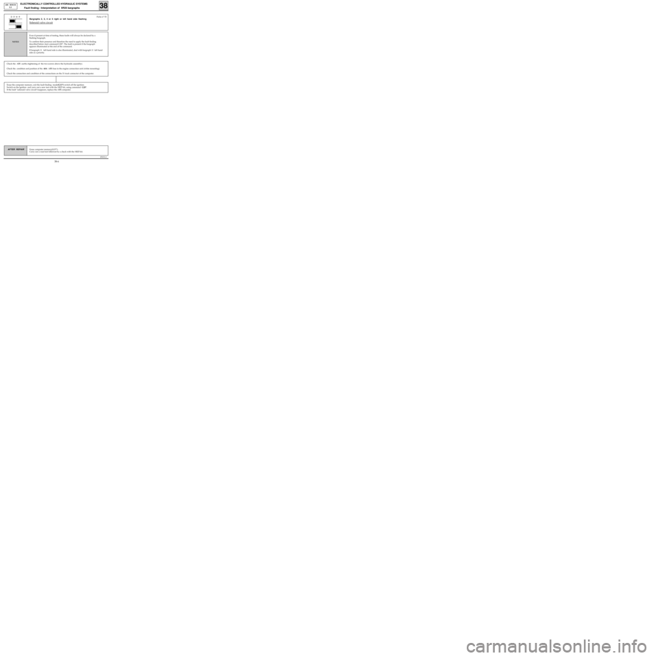
Bargraphs 2, 3, 4 or 5 right or left hand side flashing
Solenoid valve circuit
Even if present at time of testing, these faults will always be declared by a
flashing bargraph.
To confirm their presence and therefore the need to apply the fault finding
described below start command G20*. The fault is present if the bargraph
appears illuminated at the end of the command.
If bargraph 11 left hand side is also illuminated, deal with bargraph 11 left hand
side as a priority.
NOTES
Fiche n° 532 - 3 - 4 - 5
Check the ABS earths (tightening of the two screws above the hydraulic assembly).
Check the condition and position of the 60A ABS fuse in the engine connection unit (white mounting).
Check the connection and condition of the connections on the 31 track connector of the computer.
Erase the computer memory, exit the fault finding mode(G13*) switch off the ignition.
Switch on the ignition and carry out a new test with the XR25 kit, using command G20*.
If the fault "solenoid valve circuit"reappears, replace the ABS computer.
38-6
Page 275 of 363
B76531.0
ELECTRONICALLY CONTROLLED HYDRAULIC SYSTEMS
Fault finding - Interpretation of XR25 bargraphs
38
ABS BOSCH
5.3
Erase computer memory(GO**).
Carry out a road test followed by a check with the XR25 kit.AFTER REPAIR
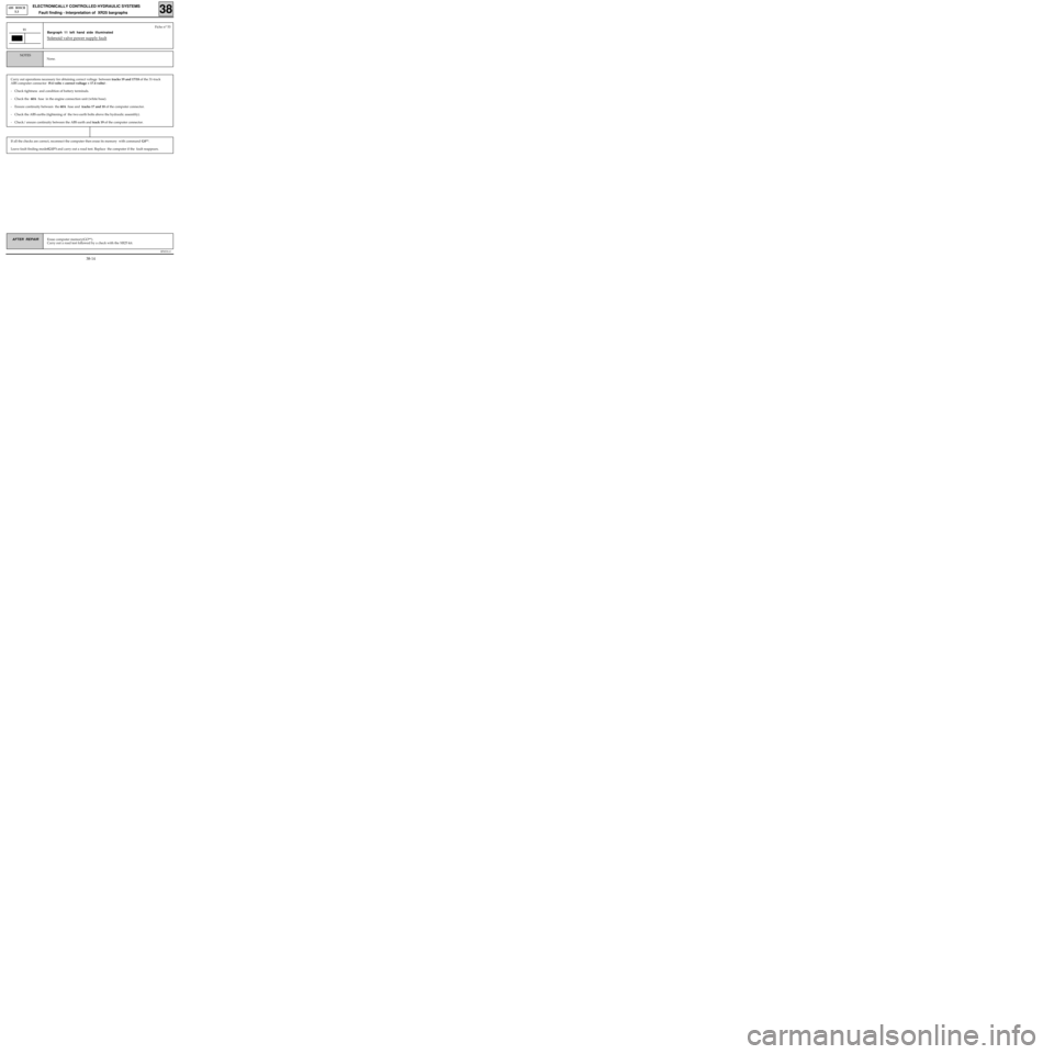
Bargraph 11 left hand side illuminated
Solenoid valve power supply fault
11Fiche n° 53
If all the checks are correct, reconnect the computer then erase its memory with command G0**.
Leave fault finding mode(G13*) and carry out a road test. Replace the computer if the fault reappears.
Carry out operations necessary for obtaining correct voltage between tracks 19 and 17/18 of the 31-track
ABS computer connector (9.4 volts < correct voltage < 17.4 volts) :
- Check tightness and condition of battery terminals.
- Check the 60A fuse in the engine connection unit (white base).
- Ensure continuity between the 60A fuse and tracks 17 and 18 of the computer connector.
- Check the ABS earths (tightening of the two earth bolts above the hydraulic assembly).
- Check/ ensure continuity between the ABS earth and track 19 of the computer connector.
None.
NOTES
38-14
Page 281 of 363
B76531.0
ELECTRONICALLY CONTROLLED HYDRAULIC SYSTEM
Fault finding - Customer Complaints38
ABS BOSCH
5.3
AFTER REPAIR Carry out a road test, then a check with the XR25 kit.
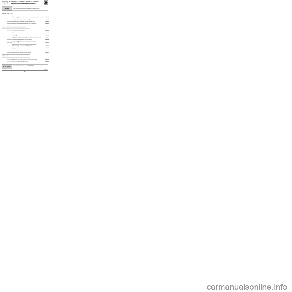
WARNING LIGHT FAULTS
ABS warning light does not illuminate for 3 seconds after ignition switched on. Chart 1
Chart 2 Permanent illumination of ABS warning light .
Chart 3
FAULTS NOTED WHEN BRAKING WITH ABS REGULATION
Locking of one or more wheels.Chart 4
Pulling.
Chart 6 Wandering.
Chart 7
Unexpected ABS operation when using special equipment
(mobile phone,CB...).
Chart 9
OTHER CASES
ABS warning light does not illuminate, computer disconnected.Chart 14
No communication with ABS computer.
Chart 15 Only consult this section after a complete check with the XR25 kit.
NOTES
ABS warning light illuminates again after engine starts.
Unexpected ABS operation at low speed and little force applied to brake.
Unexpected ABS operation on poor road surface.
Extension of brake pedal travel following a regulation phase
(with an irregular pedal when regulation begins).
Chart 5
Chart 8
Chart 10
Spongy pedal.
Brake pedal vibration.
Noise from pump, pipes or hydraulic assembly .
Chart 11
Chart 12
Chart 13 Chart 3 Temporary illumination of ABS warning light when driving.
38-20
Page 283 of 363
B76531.0
ELECTRONICALLY CONTROLLED HYDRAULIC SYSTEM
Fault finding - Fault chart 38
ABS BOSCH
5.3
AFTER REPAIR Carry out a road test, then a check with the XR25 kit.
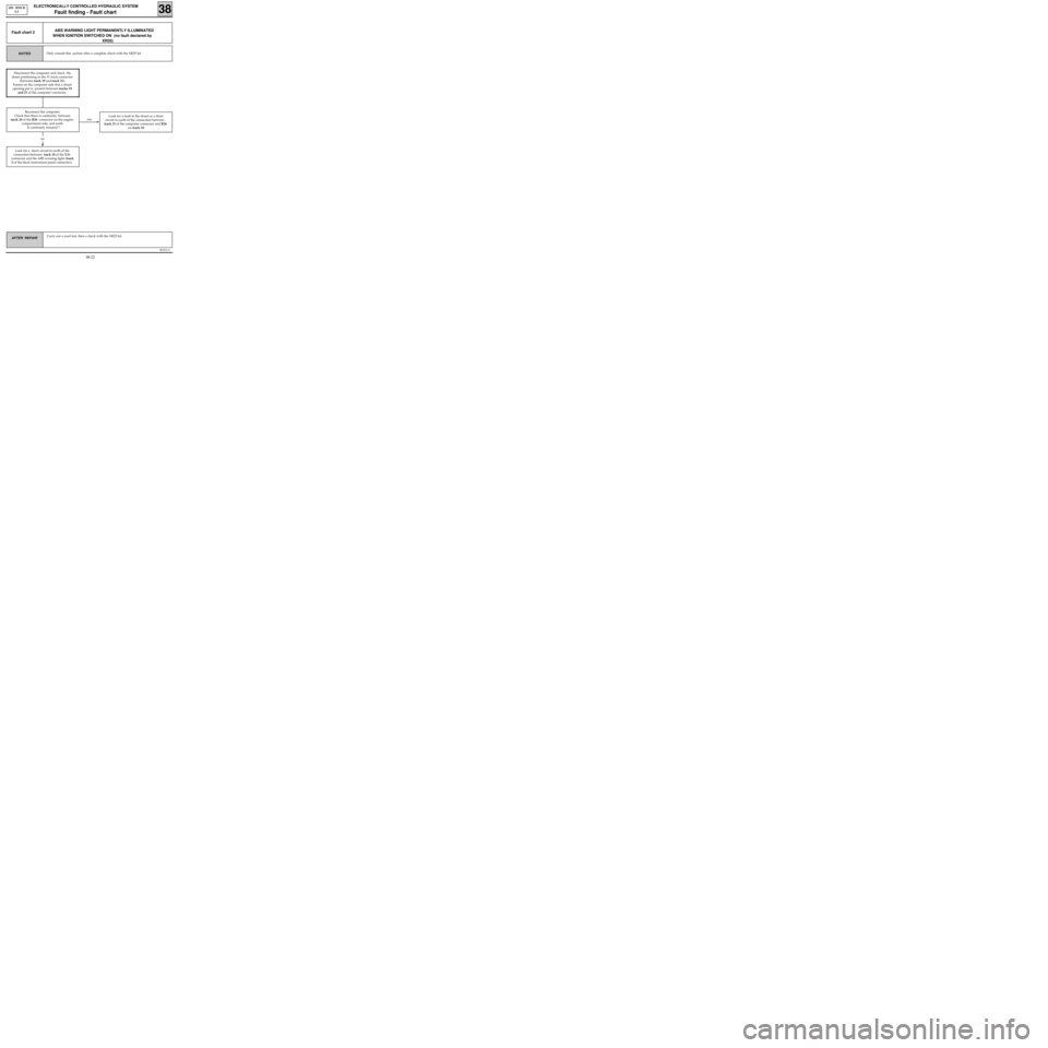
ABS WARNING LIGHT PERMANENTLY ILLUMINATED
WHEN IGNITION SWITCHED ON (no fault declared by
XR25)Fault chart 2
Only consult this section after a complete check with the XR25 kit.NOTES
yes
Look for a short circuit to earth of the
connection between track 10 of the R36
connector and the ABS warning light (track
3 of the black instrument panel connector).Look for a fault in the shunt or a short
circuit to earth of the connection between
track 21 of the computer connector and R36
on track 10.
no
Disconnect the computer and check the
shunt positioning in the 31 track connector
(between track 19 and track 21).
Ensure on the computer side that a shunt
opening pin is present between tracks 19
and 21 of the computer connector.
Reconnect the computer.
Check that there is continuity between
track 10 of the R36 connector on the engine
compartment side, and earth.
Is continuity ensured ?
38-22
Page 284 of 363
B76531.0
ELECTRONICALLY CONTROLLED HYDRAULIC SYSTEM
Fault finding - Fault chart 38
ABS BOSCH
5.3
AFTER REPAIR Carry out a road test, then a check with the XR25 kit.
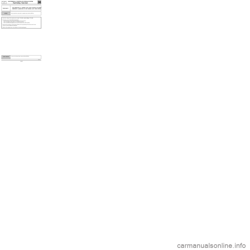
REILLUMINATION OF WARNING LIGHT AFTER STARTING THE ENGINE
TEMPORARY ILLUMINATION OF ABS WARNING LIGHT WHEN DRIVINGFault chart 3
Check the voltage of the computer power supply : 9.5 volts < correct voltage < 17.5 volts.
If necessary, carry out the following operations :
- Check the battery charge (check the charging circuit if necessary).
- Check the tightness and condition of the battery terminals.
- Check the ABS earths (tightness of two earth bolts above the ABS assembly).
Disconnect the computer and check the condition and the positioning of the shunt in the 31 track
connector (between track 19 and track 21).
Check on the computer side, the condition of the shunt opening pin.
Only consult this section after a complete check with the XR25 kit.NOTES
38-23
Page 300 of 363
v0406.0
IMMOBILISER
Fault finding- XR25 Fiche
82
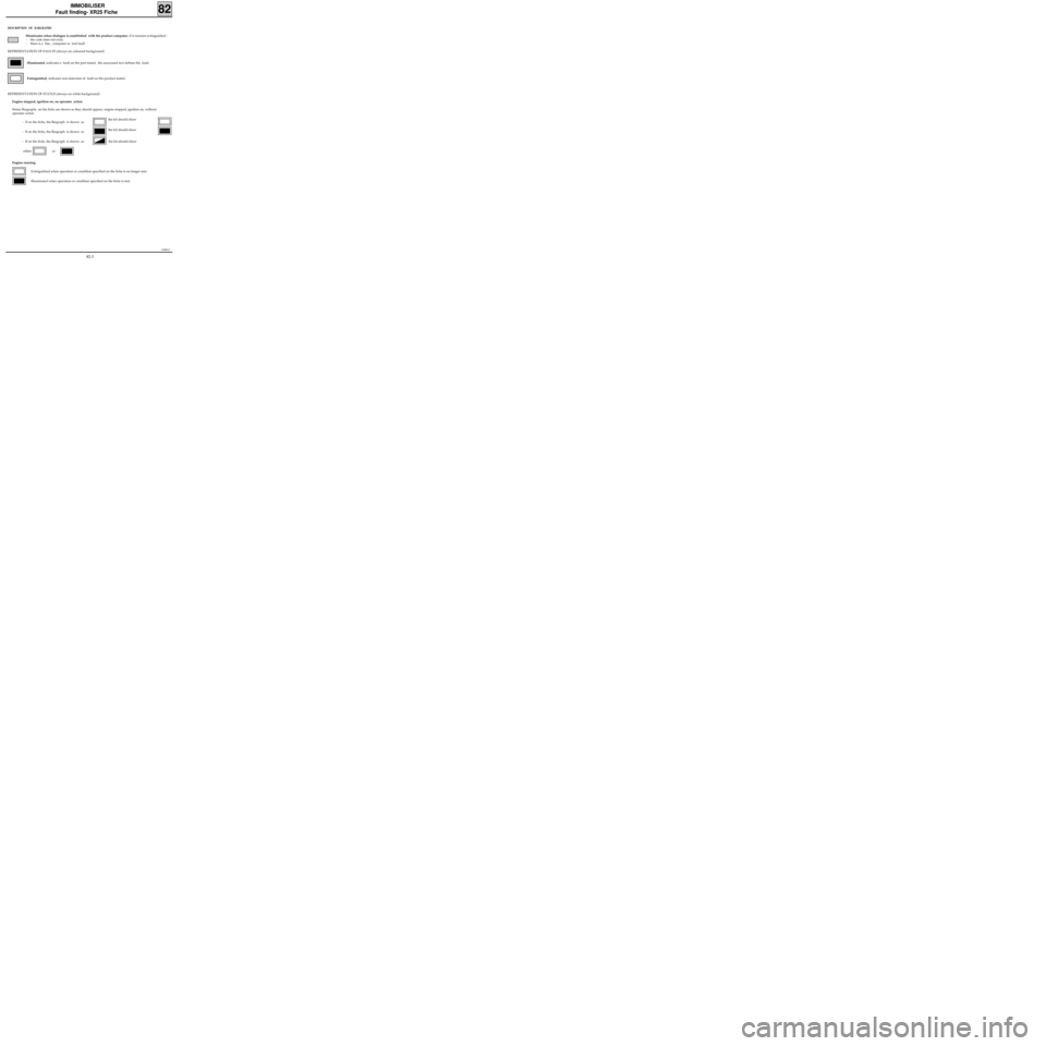
DESCRIPTION OF BARGRAPHS
Illuminates when dialogue is established with the product computer, if it remains extinguished :
- the code does not exist,
- there is a line , computer or tool fault.
REPRESENTATION OF FAULTS (always on coloured background)
Illuminated, indicates a fault on the part tested, the associated text defines the fault.
Extinguished, indicates non-detection of fault on the product tested.
REPRESENTATION OF STATUS (always on white background)
Engine stopped, ignition on, no operator action
Status Bargraphs on the fiche are shown as they should appear, engine stopped, ignition on, without
operator action
- If on the fiche, the Bargraph is shown as
- If on the fiche, the Bargraph is shown as
- If on the fiche, the Bargraph is shown as the kit should show
either or
Engine running
Extinguished when operation or condition specified on the fiche is no longer met.
Illuminated when operation or condition specified on the fiche is met.
the kit should show
the kit should show
82-3
Page 307 of 363
v0406.0
IMMOBILISER
Fault finding- Interpretation of XR25 Bargraphs 82
AFTER REPAIR
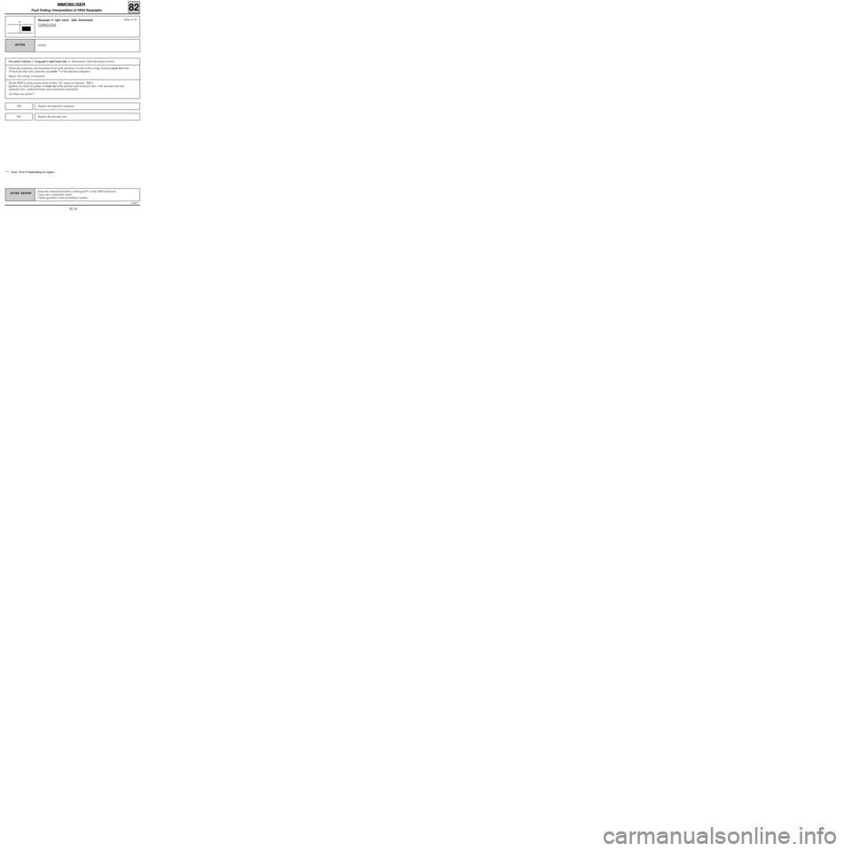
Bargraph 6 right hand side illuminated
CODED LINE
6
NONE.NOTES
Fiche n° 56
Check the continuity and insulation from earth and from 12 volts of the wiring between track A6 of the
18 track decoder unit connector and track ** of the injection computer .
Repair the wiring if necessary.
Set the XR25 to pulse sensor mode (button "G", input on terminal "Vin").
Ignition on, check for pulses on track A6 of the decoder unit connector (test with decoder unit and
solenoid valve coded electronic unit connectors connected).
Are there any pulses ?
Replace the injection computer.YES
NOReplace the decoder unit.
** track : 43 or 19 depending on engine
Erase the memorised fault by entering GO** on the XR25 keyboard.
Carry out a conformity check.
Check operation of the immobiliser system.
For petrol vehicles, if bargraph 6 right hand side is illuminated, check the impact switch.
82-10
Page 318 of 363
v0406.0
IMMOBILISER
Fault finding - Fault Chart (petrol version) 82
AFTER REPAIRCarry out a conformity check.
Check that the immobiliser system is working correctly.
Erase fault memory G0**.
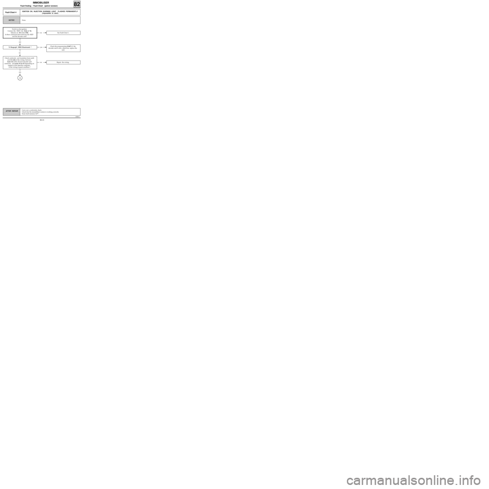
Fault Chart 4IGNITION ON, INJECTION WARNING LIGHT FLASHES PERMANENTLY
(impossible to start)
None.NOTES
Switch on the ignition.
Connect the XR25. Use fiche n° 56.
Selector on S8. Enter D56.
Is there communication between the XR25
and the decoder unit?
no See Fault Chart 1.
yes
no Repair the wiring .
yes
Check continuity and insulation from earth
and 12 volts of the wiring between
track A6 of the 18 track decoder unit
connector and track 19 (or 43 depending on
engine) of the injection computer.
Is the wiring in good condition ?
A
yesCheck the programming (G60*) if the
decoder unit is new, otherwise, replace the
unit.
no
Is Bargraph 19RH illuminated ?
82-21
Page 320 of 363
v0406.0
IMMOBILISER
Fault finding - Fault Chart (petrol version) 82
AFTER REPAIRCarry out a conformity check.
Check that the immobiliser system is working correctly.
Erase fault memory G0**.
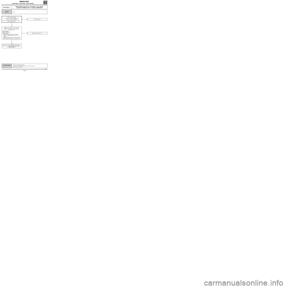
Fault Chart 5WHEN DRIVING (deceleration) AND WHEN AT IDLE SPEED,
INJECTION WARNING LIGHT FLASHES PERMANENTLY
None.NOTES
Switch on the ignition.
Connect the
XR25. Use fiche n° 56.
Selector on S8. Enter D56.
Is there communication between the XR25
and the decoder unit?
no See Fault Chart 1.
yes
no Replace the decoder unit .
XR25 still connected , check whether
BG 2RH is illuminated on the following
injection fiches:
on the Safrane:
-fiche n° 27 side 1/2
on the Laguna :
-fiche n° 13 (depending on the engine)
-fiche n° 27 side 1/2 (depending on the
engine)
-fiche n° 28 (depending on the engine) Is BG
2RH illuminated on these injection fiches?
Refer to the chart for BG 2RH injection fiche
in the section "Fault finding - Interpretation
of XR25 bargraphs ".
yes
82-23
Page 321 of 363
v0406.0
IMMOBILISER
Fault finding - Fault Chart (petrol version) 82
AFTER REPAIRCarry out a conformity check.
Check that the immobiliser system is working correctly.
Erase fault memory G0**.
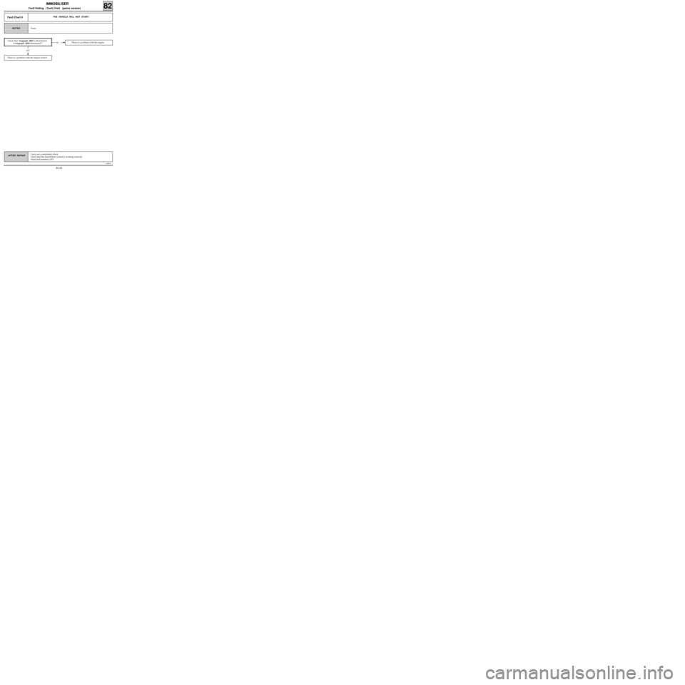
Fault Chart 6THE VEHICLE WILL NOT START
None.NOTES
no There is a problem with the engine.
There is a problem with the impact switch.
yes
Check that bargraph 6RH is illuminated .
Is bargraph 6RH illuminated ?
82-24