light RENAULT KANGOO 1997 KC / 1.G Foult Finding - Injection Owner's Manual
[x] Cancel search | Manufacturer: RENAULT, Model Year: 1997, Model line: KANGOO, Model: RENAULT KANGOO 1997 KC / 1.GPages: 363
Page 253 of 363
JSA051.0
INJECTION
Fault finding - Checking conformity
17
D7F 710
engine -
55 tracks
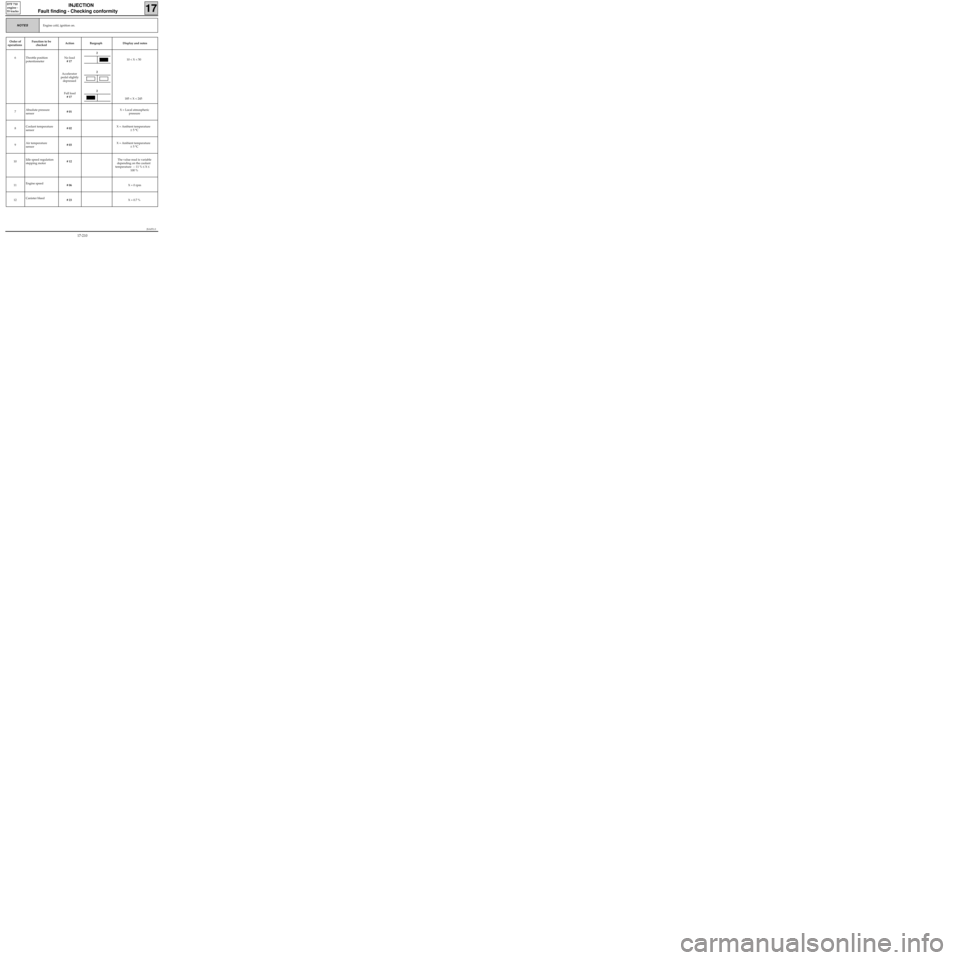
Engine cold, ignition on.NOTES
Order of
operationsFunction to be
checkedAction Bargraph Display and notes
6 Throttle position
potentiometerNo load
# 17
Accelerator
pedal slightly
depressed
Full load
# 17 10 < X < 50
185 < X < 245
7Absolute pressure
sensor# 01 X = Local atmospheric
pressure
8Coolant temperature
sensor# 02 X = Ambient temperature
± 5 °C
9Air temperature
sensor# 03 X = Ambient temperature
± 5 °C
10Idle speed regulation
stepping motor# 12The value read is variable
depending on the coolant
temperature : : 11 % ≤ X ≤
100 %
11Engine speed
# 06 X = 0 rpm
12Canister bleed
# 23 X = 0.7 %
2
2
2
17-210
Page 258 of 363
JSA051.0
INJECTION
Fault finding - Checking conformity
17
D7F 710
engine -
55 tracks
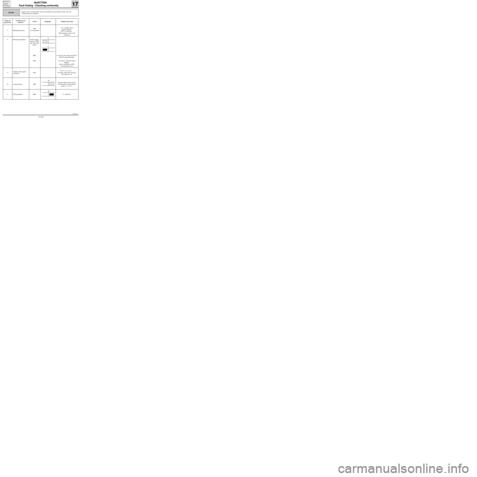
NOTES
Order of
operationsFunction to be
checkedAction Bargraph Display and notes
7 Manifold pressure# 01
no consumers X is variable and is
approximately
270 ≤ X ≤ 430 mb
(this pressure varies with
altitude)
8 Richness regulation Stable engine
speed of 2500
rpm then idle
speed
# 05
# 35X varies in the range from 50 to
900 mV approximately
X is close to 128 and varies
slightly
with a maximum of 255
and minimum of 0
9Adaptive idle speed
correction# 21- 4.3 % < X < 3.9 %
(average value after erasing
the memory : 0)
10 Canister bleed# 23Canister bleed is prevented.
The solenoid valve remains
closed. X = 0.7 %
11 PAS pressostat# 06X = 800 rpm
Engine warm, at idle speed, after fan assembly has operated at least once (air
conditioning not selected)
6
6
11
13
17-215
Page 262 of 363
B76531.0
ELECTRONICALLY CONTROLLED HYDRAULIC SYSTEMS
Fault finding - Introduction38
ABS BOSCH
5.3
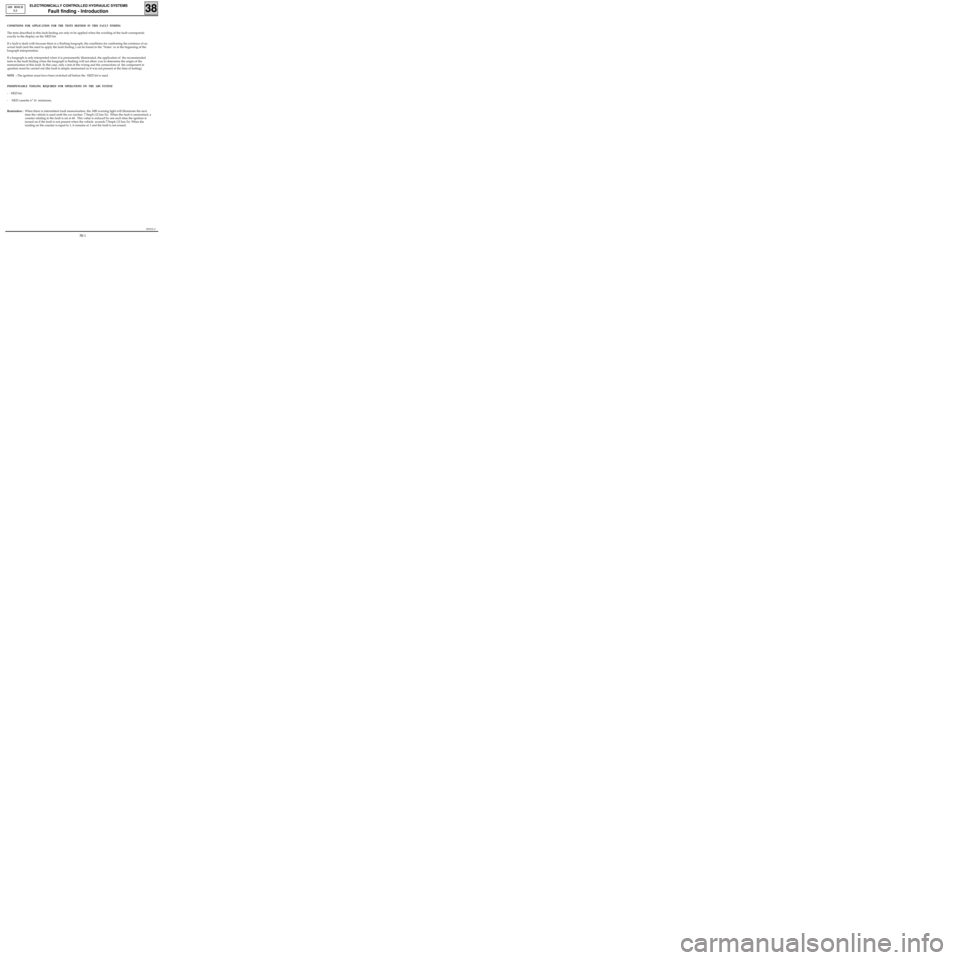
CONDITIONS FOR APPLICATION FOR THE TESTS DEFINED IN THIS FAULT FINDING
The tests described in this fault finding are only to be applied when the wording of the fault corresponds
exactly to the display on the XR25 kit.
If a fault is dealt with because there is a flashing bargraph, the conditions for confirming the existence of an
actual fault (and the need to apply the fault finding ) can be found in the "Notes" or at the beginning of the
bargraph interpretation.
If a bargraph is only interpreted when it is permanently illuminated, the application of the recommended
tests in the fault finding when the bargraph is flashing will not allow you to determine the origin of the
memorisation of this fault. In this case, only a test of the wiring and the connections of the component in
question must be carried out (the fault is simply memorised as it was not present at the time of testing).
NOTE : The ignition must have been switched off before the XR25 kit is used.
INDISPENSABLE TOOLING REQUIRED FOR OPERATIONS ON THE ABS SYSTEM
- XR25 kit.
- XR25 cassette n° 16 minimum.
Reminders :When there is intermittent fault memorisation, the ABS warning light will illuminate the next
time the vehicle is used until the car reaches 7.5mph (12 km/h). When the fault is memorised, a
counter relating to the fault is set at 40 . This value is reduced by one each time the ignition is
turned on if the fault is not present when the vehicle exceeds 7.5mph (12 km/h). When the
reading on the counter is equal to 1, it remains at 1 and the fault is not erased.
38-1
Page 276 of 363
B76531.0
ELECTRONICALLY CONTROLLED HYDRAULIC SYSTEMS
Fault finding - Interpretation of XR25 bargraphs
38
ABS BOSCH
5.3
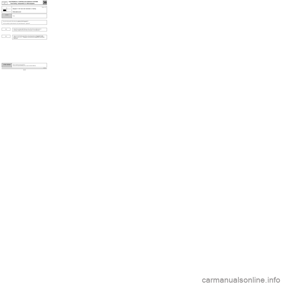
Erase computer memory(GO**).
Carry out a road test followed by a check with the XR25 kit.AFTER REPAIR
Bargraph 12 left hand side illuminated or flashing
Brake light circuit
12Fiche n° 53
Press the brake pedal while observing right and left bargraph 13.
Are the positions "pedal released" and "pedal depressed" registered?
None.
NOTES
YESCheck the two brake light bulbs and the earth of the rear light units (no
earthing of track 14 across the bulbs when pedal is not depressed ).
NOApply the fault finding described in the interpretation of bargraph 13 right
and left hand side for "Bargraph 13 left hand side extinguished, brake pedal
depressed".
38-15
Page 278 of 363
B76531.0
ELECTRONICALLY CONTROLLED HYDRAULIC SYSTEMS
Fault finding - Interpretation of XR25 bargraphs
38
ABS BOSCH
5.3
AFTER REPAIR
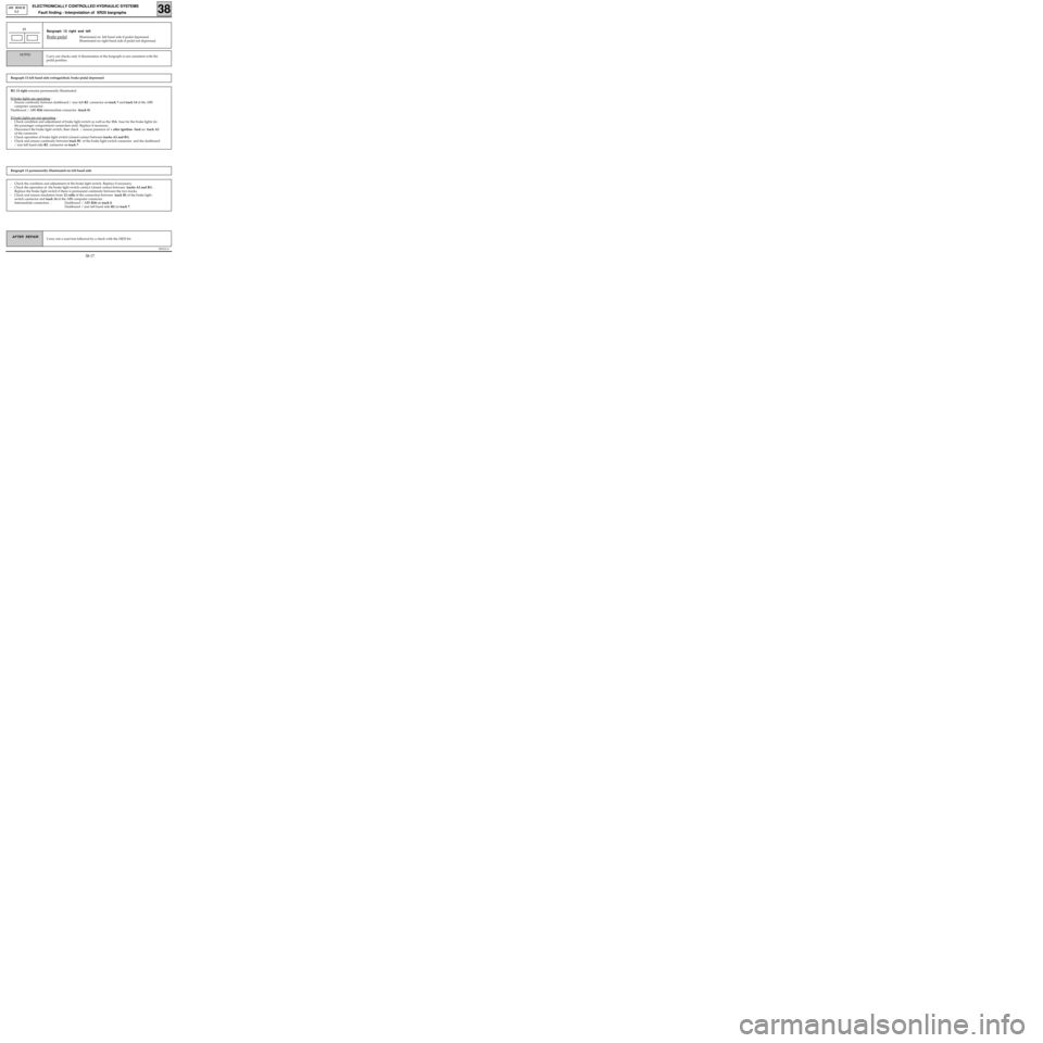
13Fiche n° 53
Bargraph 13 left hand side extinguished, brake pedal depressed
Carry out checks only if illumination of the bargraph is not consistent with the
pedal position. NOTES
Bargraph 13 right and left
Brake pedalIlluminated on left hand side if pedal depressed.
Illuminated on right hand side if pedal not depressed.
BG 13 right remains permanently illuminated.
If brake lights are operating
:
- Ensure continuity between dashboard / rear left R2 connector on track 7 and track 14 of the ABS
computer connector .
Dashboard / ABS R36 intermediate connector (track 8).
If brake lights are not operating
:
- Check condition and adjustment of brake light switch as well as the 15A fuse for the brake lights (in
the passenger compartment connection unit). Replace if necessary.
- Disconnect the brake light switch, then check / ensure presence of + after ignition feed on track A3
of the connector
- Check operation of brake light switch (closed contact between tracks A3 and B1).
- Check and ensure continuity between track B1 of the brake light switch connector and the dashboard
/ rear left hand side R2 connector on track 7.
Bargraph 13 permanently illuminated on left hand side
- Check the condition and adjustment of the brake light switch. Replace if necessary.
- Check the operation of the brake light switch contact (closed contact between tracks A3 and B1).
Replace the brake light switch if there is permanent continuity between the two tracks.
- Check and ensure insulation from 12 volts of the connection between track B1 of the brake light
switch connector and track 14 of the ABS computer connector .
Intermediate connectors : Dashboard / ABS R36 on track 8.
Dashboard / rear left hand side R2 on track 7.
Carry out a road test followed by a check with the XR25 kit.
38-17
Page 279 of 363
B76531.0
ELECTRONICALLY CONTROLLED HYDRAULIC SYSTEMS
Fault finding - Conformity Check38
ABS BOSCH
5.3
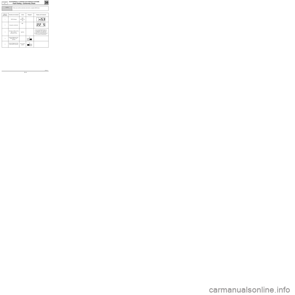
Order of
operationsFunction to be checked Action Bargraph Display and Comments
1 XR25 dialogueD11
(selector on
S8)
2 Computer conformity#12
3
Operation of ABS warning
light- computer
initialisation check
IgnitionTwo second illumination of
warning light when ignition is
switched on (consult fault
finding if it remains illuminated
or if it does not illuminate)
4Acknowledgement that
brake pedal is not
pressed
5Acknowledgement that
brake pedal is pressedPress brake
pedal
Only carry out this conformity check after a complete XR25 check.NOTES
13
13
38-18
Page 281 of 363
B76531.0
ELECTRONICALLY CONTROLLED HYDRAULIC SYSTEM
Fault finding - Customer Complaints38
ABS BOSCH
5.3
AFTER REPAIR Carry out a road test, then a check with the XR25 kit.
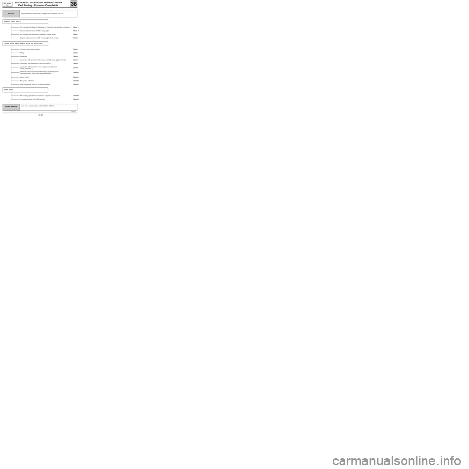
WARNING LIGHT FAULTS
ABS warning light does not illuminate for 3 seconds after ignition switched on. Chart 1
Chart 2 Permanent illumination of ABS warning light .
Chart 3
FAULTS NOTED WHEN BRAKING WITH ABS REGULATION
Locking of one or more wheels.Chart 4
Pulling.
Chart 6 Wandering.
Chart 7
Unexpected ABS operation when using special equipment
(mobile phone,CB...).
Chart 9
OTHER CASES
ABS warning light does not illuminate, computer disconnected.Chart 14
No communication with ABS computer.
Chart 15 Only consult this section after a complete check with the XR25 kit.
NOTES
ABS warning light illuminates again after engine starts.
Unexpected ABS operation at low speed and little force applied to brake.
Unexpected ABS operation on poor road surface.
Extension of brake pedal travel following a regulation phase
(with an irregular pedal when regulation begins).
Chart 5
Chart 8
Chart 10
Spongy pedal.
Brake pedal vibration.
Noise from pump, pipes or hydraulic assembly .
Chart 11
Chart 12
Chart 13 Chart 3 Temporary illumination of ABS warning light when driving.
38-20
Page 282 of 363
B76531.0
ELECTRONICALLY CONTROLLED HYDRAULIC SYSTEM
Fault finding - Fault chart 38
ABS BOSCH
5.3
AFTER REPAIR Carry out a road test, then a check with the XR25 kit.
yes
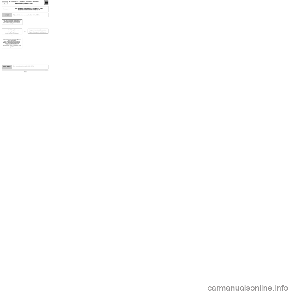
ABS WARNING LIGHT DOES NOT ILLUMINATE FOR 3
SECONDS WHEN IGNITION SWITCHED ONFault chart 1
Only consult this section after a complete check with the XR25 kit.NOTES
Check condition of ABS warning light bulb
and its power supply.
Ensure continuity of connection between
track 21 of the computer connector and the
warning light (track 3 of the black
instrument panel connector).
If fault persists, check the instrument panel
operation.
Carry out an inspection of the connections
on the 31 track connector.
Replace the computer if the fault persists.
no
Check the 15A instrument panel fuse on the
passenger compartment connection unit
(if the problem affects all instrument panel
operations).
Turn off the ignition.
Disconnect the computer, then switch on
the ignition again.
Does the warning light illuminate?
38-21
Page 283 of 363
B76531.0
ELECTRONICALLY CONTROLLED HYDRAULIC SYSTEM
Fault finding - Fault chart 38
ABS BOSCH
5.3
AFTER REPAIR Carry out a road test, then a check with the XR25 kit.
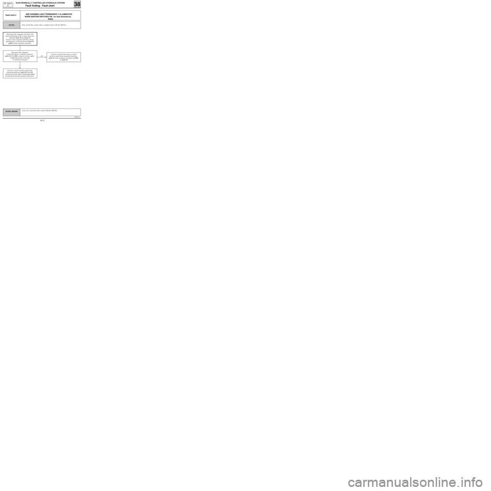
ABS WARNING LIGHT PERMANENTLY ILLUMINATED
WHEN IGNITION SWITCHED ON (no fault declared by
XR25)Fault chart 2
Only consult this section after a complete check with the XR25 kit.NOTES
yes
Look for a short circuit to earth of the
connection between track 10 of the R36
connector and the ABS warning light (track
3 of the black instrument panel connector).Look for a fault in the shunt or a short
circuit to earth of the connection between
track 21 of the computer connector and R36
on track 10.
no
Disconnect the computer and check the
shunt positioning in the 31 track connector
(between track 19 and track 21).
Ensure on the computer side that a shunt
opening pin is present between tracks 19
and 21 of the computer connector.
Reconnect the computer.
Check that there is continuity between
track 10 of the R36 connector on the engine
compartment side, and earth.
Is continuity ensured ?
38-22
Page 284 of 363
B76531.0
ELECTRONICALLY CONTROLLED HYDRAULIC SYSTEM
Fault finding - Fault chart 38
ABS BOSCH
5.3
AFTER REPAIR Carry out a road test, then a check with the XR25 kit.
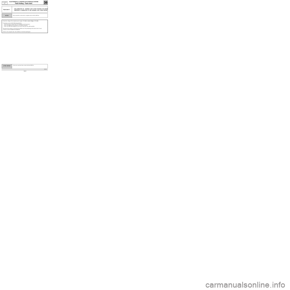
REILLUMINATION OF WARNING LIGHT AFTER STARTING THE ENGINE
TEMPORARY ILLUMINATION OF ABS WARNING LIGHT WHEN DRIVINGFault chart 3
Check the voltage of the computer power supply : 9.5 volts < correct voltage < 17.5 volts.
If necessary, carry out the following operations :
- Check the battery charge (check the charging circuit if necessary).
- Check the tightness and condition of the battery terminals.
- Check the ABS earths (tightness of two earth bolts above the ABS assembly).
Disconnect the computer and check the condition and the positioning of the shunt in the 31 track
connector (between track 19 and track 21).
Check on the computer side, the condition of the shunt opening pin.
Only consult this section after a complete check with the XR25 kit.NOTES
38-23