light RENAULT KANGOO 1997 KC / 1.G Foult Finding - Injection User Guide
[x] Cancel search | Manufacturer: RENAULT, Model Year: 1997, Model line: KANGOO, Model: RENAULT KANGOO 1997 KC / 1.GPages: 363
Page 113 of 363
JF5111.0
INJECTION
Fault finding - Checking conformity
17
E7J 780
engine
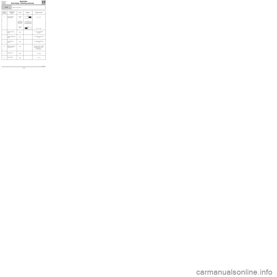
Engine cold, ignition on.NOTES
Order of
operationsFunction to be
checkedAction Bargraph Display and notes
6 Throttle position
potentiometerNo load
# 17
Accelerator
pedal slightly
depressed
Full load
# 17 16 < X < 50
185 < X < 243
7Absolute pressure
sensor# 01 X = Local atmospheric
pressure
8Coolant temperature
sensor# 02 X = Ambient temperature
± 5 °C
9Air temperature
sensor# 03 X = Ambient temperature
± 5 °C
10Idle speed regulation
stepping motor# 12The value read is variable
depending on the coolant
temperature :
7 % ≤ X ≤ 100 %
11Engine speed
# 06 X = 0 rpm
12Canister bleed
# 23 X = 0.7 %
2
2
2
17-65
Page 117 of 363
JF5111.0
INJECTION
Fault finding - Checking conformity
17
E7J 780
engine
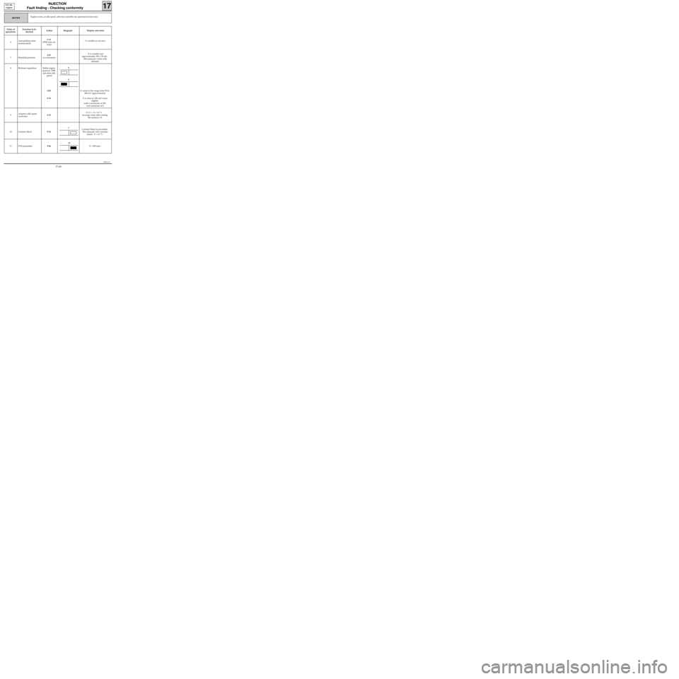
NOTES
Order of
operationsFunction to be
checkedAction Bargraph Display and notes
6Anti-pinking noise
measurement# 13
(3500 rpm, no
load) X variable or not zero
7 Manifold pressure# 01
no consumers X is variable and
approximately 350 ± 50 mb
(this pressure varies with
altitude)
8 Richness regulation Stable engine
speed of 2500
rpm then idle
speed
# 05
# 35X varies in the range from 50 to
900 mV approximately
X is close to 128 and varies
slightly
with a maximum of 255
and minimum of 0
9Adaptive idle speed
correction# 21- 2.4 % < X < 6.2 %
(average value after erasing
the memory: 0)
10 Canister bleed# 23Canister bleed is prevented.
The solenoid valve remains
closed. X = 0.7 %
11 PAS pressostat# 06X = 850 rpm
Engine warm, at idle speed, after fan assembly has operated at least once.
6
6
7
13
17-69
Page 142 of 363
Connect the bornier in place of the computer and check the insulation and continuity of the line:
Computer 19 6 Instrument panel
Repair.
JSA051.0
INJECTION
Fault finding - Interpretation of XR25 bargraphs17
D7F 710
engine -
35 tracks
Erase the computer memory using G0**.
Try to start the engine. Switch the ignition on, then deal with the other faults.
Remember to carry out a status and parameter check.AFTER REPAIR
Bargraph 12 LH side illuminatedFiche n° 27 side 1/2
FAULT WARNING LIGHT CIRCUIT
XR25 aid:CO, CC- or CC+ line 19 of the computer
12
NoneNOTES
Check the condition of the warning light and its feed.
Repair if necessary.
17-97
Page 149 of 363
JSA051.0
INJECTION
Fault finding - Status and parameter checks
17
D7F 710
engine -
35 tracks
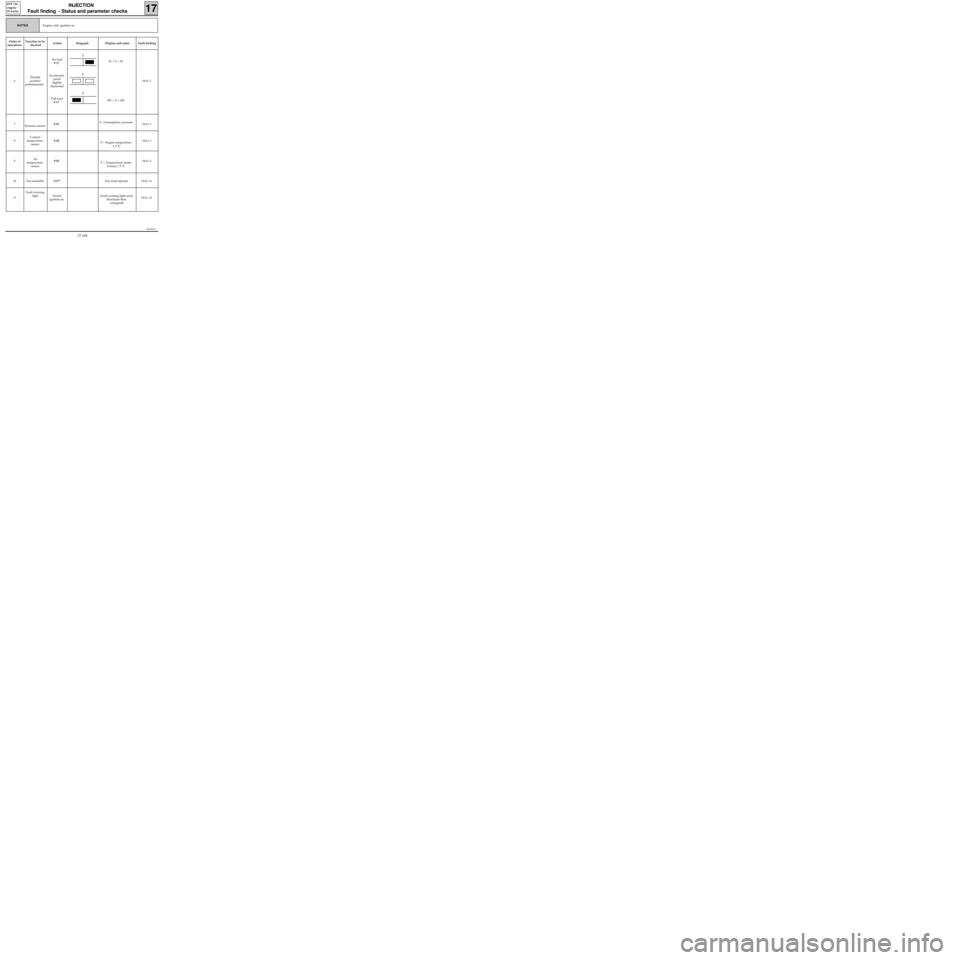
Engine cold, ignition on.NOTES
Order of
operationsFunction to be
checkedAction Bargraph Display and notes Fault finding
6Throttle
position
potentiometer
.No load
# 17
Accelerator
pedal
slightly
depressed
Full load
# 1710 < X < 50
185 < X < 245
DIAG 2
7
Pressure sensor# 01X =Atmospheric pressureDIAG 9
8Coolant
temperature
sensor# 02
X = Engine temperature
± 5 °CDIAG 3
9Air
temperature
sensor# 03
X = Temperature under
bonnet ± 5 °CDIAG 4
10 Fan assemblyG17*Fan must operateDIAG 16
11Fault warning
light Switch
ignition onFault warning light must
illuminate then
extinguishDIAG 18
2
2
2
17-104
Page 172 of 363
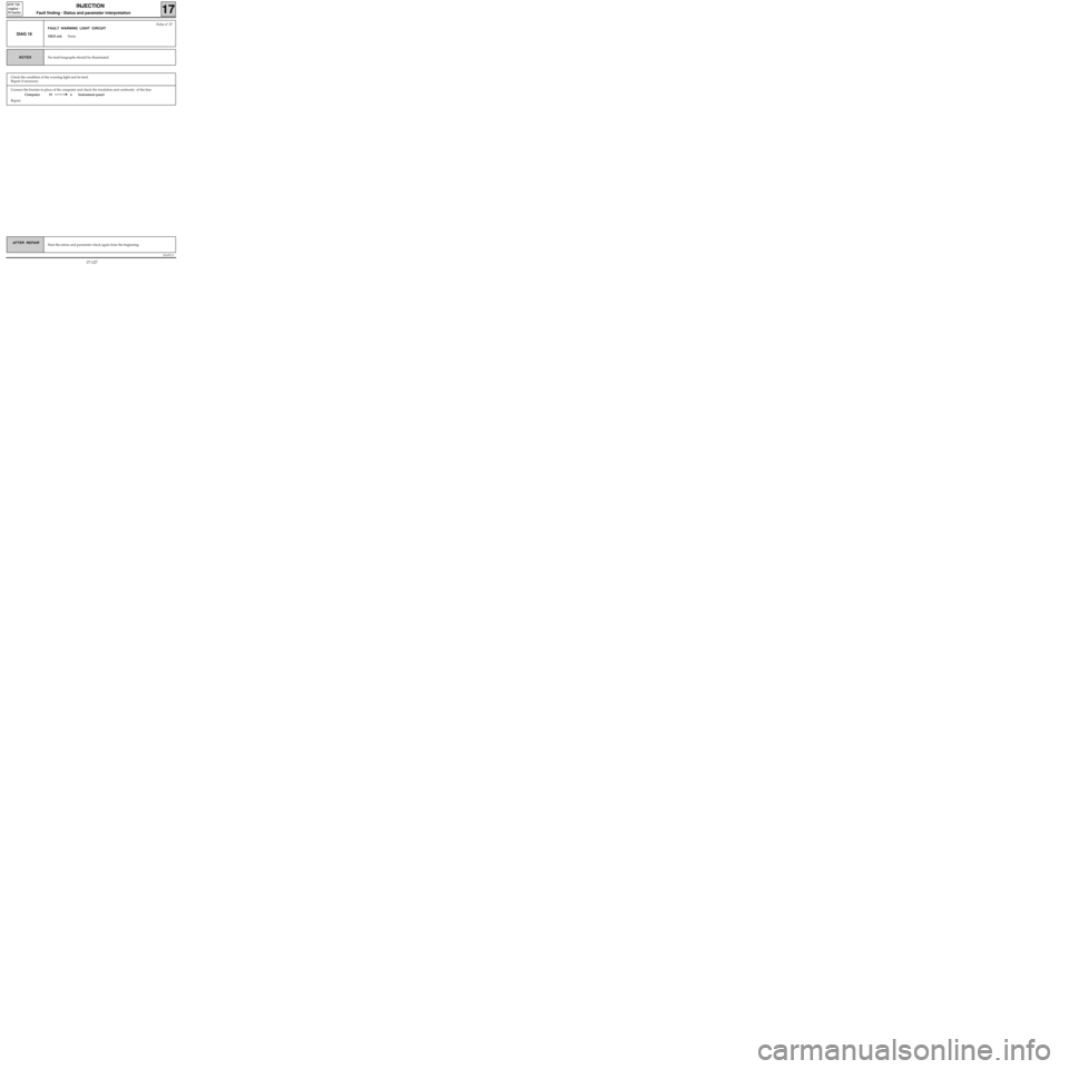
Connect the bornier in place of the computer and check the insulation and continuity of the line:
Computer 19 6 Instrument panel
Repair.
JSA051.0
INJECTION
Fault finding - Status and parameter interpretation17
D7F 710
engine -
35 tracks
AFTER REPAIRStart the status and parameter check again from the beginning.
DIAG 18
Fiche n° 27
FAULT WARNING LIGHT CIRCUIT
XR25 aid:None
No fault bargraphs should be illuminated.NOTES
Check the condition of the warning light and its feed.
Repair if necessary.
17-127
Page 182 of 363
JSA051.0
INJECTION
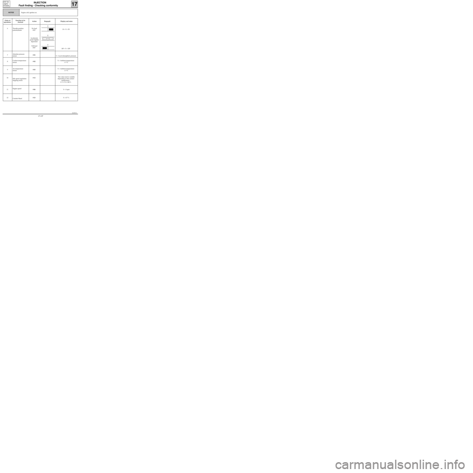
Fault finding - Checking conformity
17
D7F 710
engine -
35 tracks
Engine cold, ignition on.NOTES
Order of
operationsFunction to be
checkedAction Bargraph Display and notes
6 Throttle position
potentiometerNo load
# 17
Accelerator
pedal slightly
depressed
Full load
# 17 10 < X < 50
185 < X < 245
7Absolute pressure
sensor# 01
X = Local atmospheric pressure
8Coolant temperature
sensor# 02 X = Ambient temperature
± 5 °C
9Air temperature
sensor# 03 X = Ambient temperature
± 5 °C
10
Idle speed regulation
stepping motor# 12The value read is variable
depending on the coolant
temperature :
11 % ≤ X ≤ 100 %
11Engine speed
# 06 X = 0 rpm
12
Canister bleed# 23 X = 0.7 %
2
2
2
17-137
Page 186 of 363
JSA051.0
INJECTION
Fault finding - Checking conformity
17
D7F 710
engine -
35 tracks
NOTES
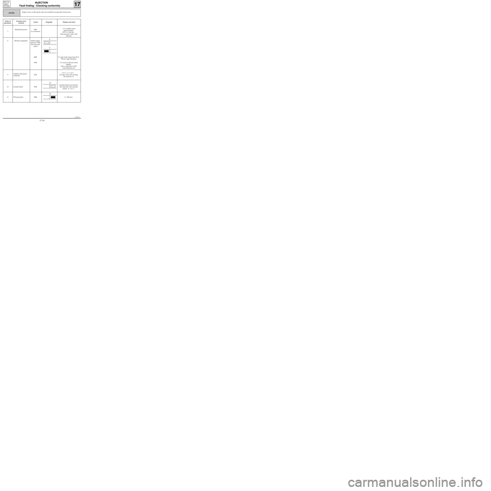
Order of
operationsFunction to be
checkedAction Bargraph Display and notes
7Manifold pressure# 01
no consumers X is variable and is
approximately
270 ≤ X ≤ 430 mb
(this pressure varies with
altitude)
8 Richness regulation Stable engine
speed of 2500
rpm then idle
speed
# 05
# 35X varies in the range from 50 to
900 mV approximately
X is close to 128 and varies
slightly
with a maximum of 255
and minimum of 0
9Adaptive idle speed
correction# 21- 4.3 % < X < 3.9 %
(average value after erasing
the memory: 0)
10 Canister bleed# 23Canister bleed is prevented.
The solenoid valve remains
closed. X = 0.7 %
11 PAS pressostat# 06X = 800 rpm
Engine warm, at idle speed, after fan assembly has operated at least once
6
6
11
13
17-141
Page 212 of 363
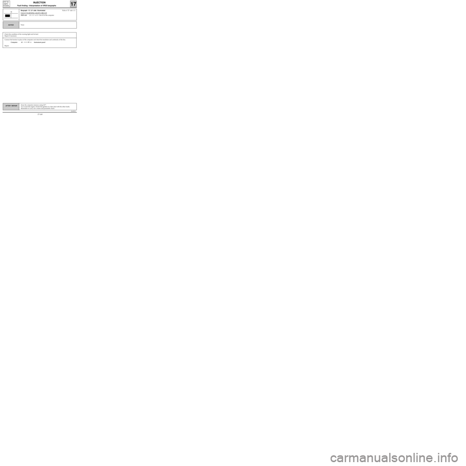
Connect the bornier in place of the computer and check the insulation and continuity of the line.
Computer 43 6 Instrument panel
Repair.
JSA052.0
INJECTION
Fault finding - Interpretation of XR25 bargraphs17
D7F 710
engine -
55 tracks
Erase the computer memory using G0**.
Try to start the engine. Switch the ignition on, then deal with the other faults.
Remember to carry out a status and parameter check.AFTER REPAIR
Bargraph 12 LH side illuminatedFiche n° 27 side 1/2
FAULT WARNING LIGHT CIRCUIT
XR25 aid:CO, CC- or CC+ line 43 of the computer
12
NoneNOTES
Check the condition of the warning light and its feed.
Repair if necessary.
17-169
Page 219 of 363
JSA052.0
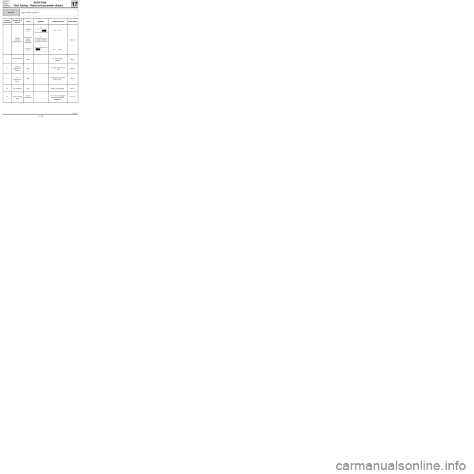
INJECTION
Fault finding - Status and parameter checks
17
D7F 710
engine -
55 tracks
Engine stopped, ignition on.NOTES
Order of
operationsFunction to be
checkedAction Bargraph Display and notes Fault finding
6Throttle
position
potentiometer
.No load
# 17
Accelerator
pedal
slightly
depressed
Full load
# 1710 < X < 50
185 < X < 245
DIAG 2
7Pressure sensor
# 01X = Atmospheric
pressureDIAG 9
8Coolant
temperature
sensor# 02X = Engine temperature
± 5 °CDIAG 3
9Air
temperature
sensor# 03X = Temperature under
bonnet ± 5 °CDIAG 4
10 Fan assemblyG17*The fan must operateDIAG 17
11 Fault warning
lightSwitch
ignition onThe fault warning light
must illuminate then
extinguishDIAG 19
2
2
2
17-176
Page 243 of 363
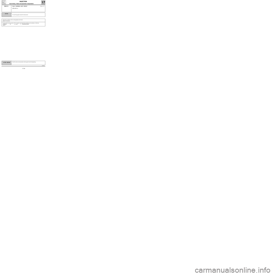
Connect the bornier in place of the computer and check the insulation and continuity of the line:
Computer 43 6 Instrument panel
Repair.
JSA052.0
INJECTION
Fault finding - Status and parameter interpretation17
D7F 710
engine -
55 tracks
AFTER REPAIRStart the status and parameter check again from the beginning.
DIAG 19FAULT WARNING LIGHT CIRCUITFiche n° 27
XR25 aid:None
No fault bargraphs should be illuminated.
NOTES
Check the condition of the warning light and its feed.
Repair if necessary.
17-200