air condition RENAULT KANGOO 1997 KC / 1.G Foult Finding - Injection Repair Manual
[x] Cancel search | Manufacturer: RENAULT, Model Year: 1997, Model line: KANGOO, Model: RENAULT KANGOO 1997 KC / 1.GPages: 363
Page 198 of 363
Connect the bornier in place of the computer and check the insulation and continuity of the line:
Computer 18 Earth
Computer 2 Earth
Computer 3 Earth
Computer 11 7 Diagnostic socket
Computer 38 15 Diagnostic socket
Computer 1 5 Main relay
Computer 40 2 Main relay
Computer 48 2 Fuel pump relay
Repair if necessary.
JSA052.0
INJECTION
Fault finding - Interpretation of XR25 bargraphs17
D7F 710
engine -
55 tracks
Erase the computer memory using G0**.
Try to start the engine. Switch the ignition on, then deal with the other faults.
Remember to carry out a status and parameter check.AFTER REPAIR
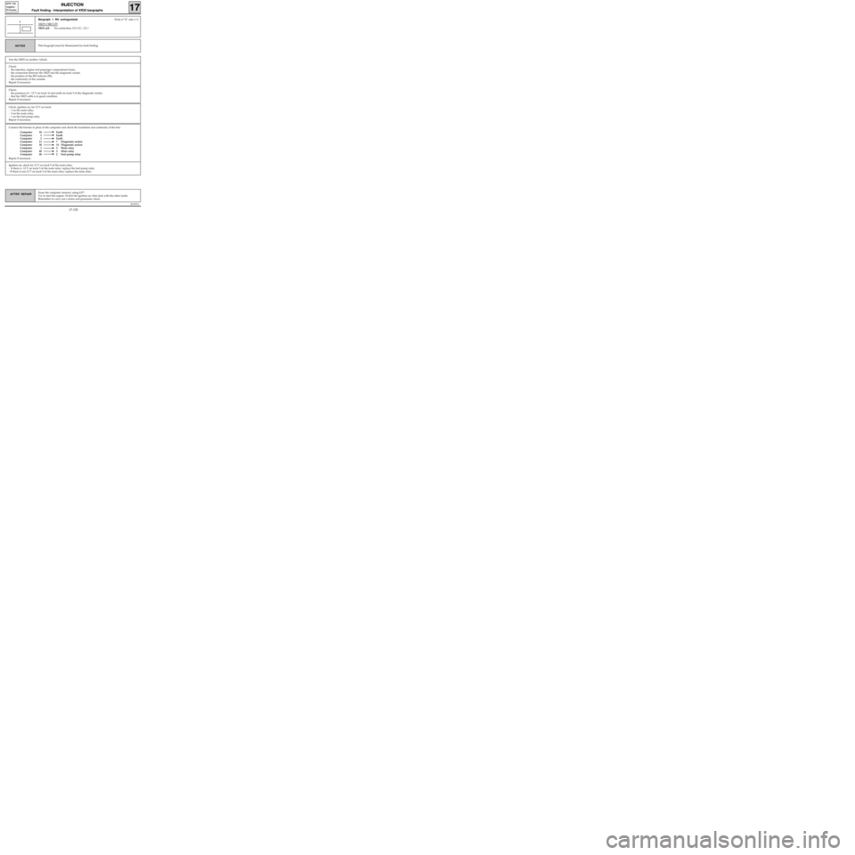
Bargraph 1 RH extinguishedFiche n° 27 side 1/2
XR25 CIRCUIT
XR25 aid:No connection, CO, CC-, CC+
1
This bargraph must be illuminated for fault findingNOTES
Test the XR25 on another vehicle.
Check:
- the injection, engine and passenger compartment fuses,
- the connection between the XR25 and the diagnostic socket,
- the position of the ISO selector (S8),
- the conformity of the cassette.
Repair if necessary.
Check:
- the presence of + 12 V on track 16 and earth on track 5 of the diagnostic socket,
- that the XR25 cable is in good condition.
Repair if necessary.
Check, ignition on, for 12 V on track:
- 1 on the main relay,
- 3 on the main relay,
- 1 on the fuel pump relay.
Repair if necessary.
Ignition on, check for 12 V on track 5 of the main relay:
- If there is 12 V on track 5 of the main relay: replace the fuel pump relay.
- If there is not 12 V on track 5 of the main relay: replace the main relay.
17-155
Page 202 of 363
Connect the bornier in place of the computer and check the insulation and continuity of the line:
Computer 17 C Oxygen sensor
Repair if necessary.
JSA052.0
INJECTION
Fault finding - Interpretation of XR25 bargraphs17
D7F 710
engine -
55 tracks
Turn the engine, switch the ignition on and erase the computer memory using
G0**. Try to start the engine. Switch the ignition on, then deal with the other
faults. Remember to carry out a status and parameter check.AFTER REPAIR
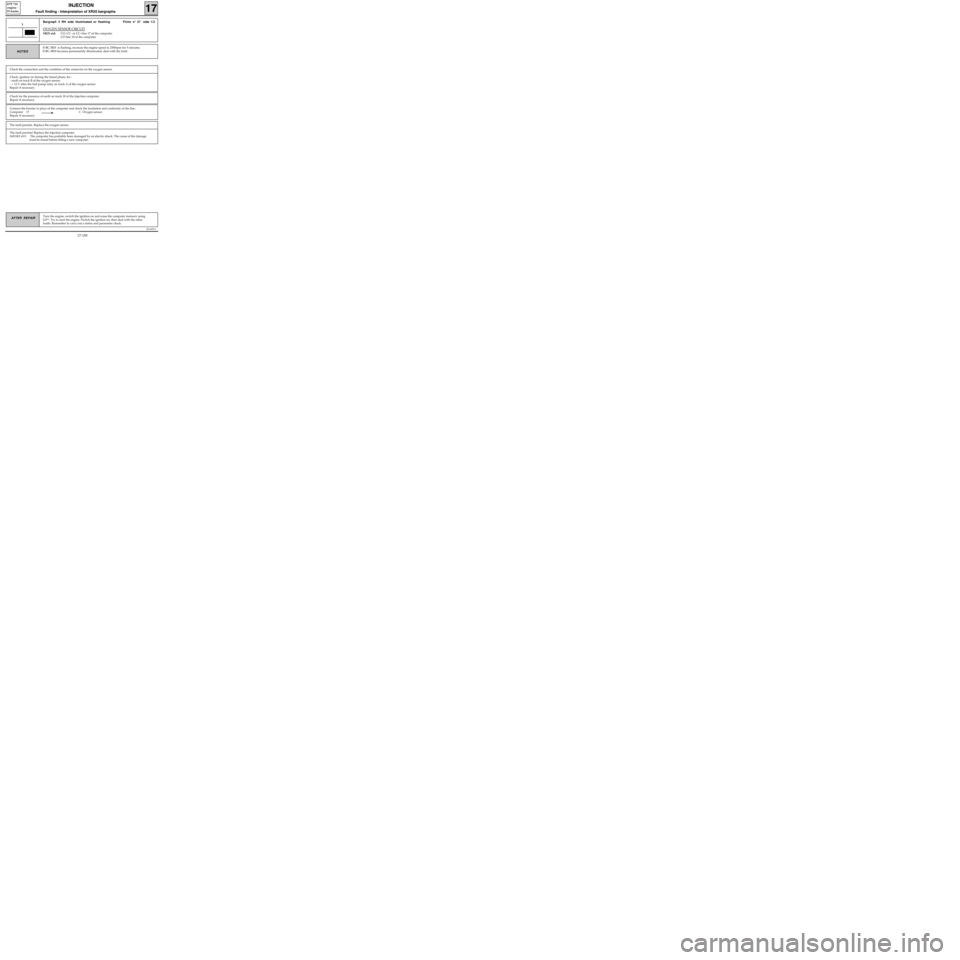
Bargraph 3 RH side illuminated or flashing Fiche n° 27 side 1/2
OXYGEN SENSOR CIRCUIT
XR25 aid:CO, CC- or CC+line 17 of the computer
CO line 18 of the computer
3
If BG 3RH is flashing, increase the engine speed to 2500rpm for 5 minutes.
If BG 3RH becomes permanently illuminated, deal with the fault.
NOTES
Check the connection and the condition of the connector on the oxygen sensor.
Check, ignition on during the timed phase, for :
- earth on track B of the oxygen sensor,
- + 12 V after the fuel pump relay on track A of the oxygen sensor.
Repair if necessary.
Check for the presence of earth on track 18 of the injection computer.
Repair if necessary.
The fault persists. Replace the oxygen sensor.
The fault persists! Replace the injection computer.
IMPORTANT: The computer has probably been damaged by an electric shock. The cause of the damage
must be found before fitting a new computer.
17-159
Page 206 of 363
Connect the bornier in place of the computer and check the insulation,
continuity and that there is no interference resistance on the line:
Computer 33 B Target sensor
Computer 34 A Target sensor
Repair if necessary.
JSA052.0
INJECTION
Fault finding - Interpretation of XR25 bargraphs17
D7F 710
engine -
55 tracks
Erase the computer memory using G0**.
Try to start the engine. Switch the ignition on, then deal with the other faults.
Remember to carry out a status and parameter check.AFTER REPAIR
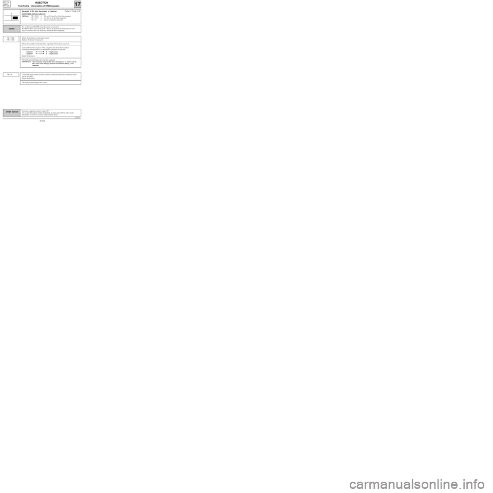
Bargraph 5 RH side illuminated or flashingFiche n° 2 side 1/2
FLYWHEEL SIGNAL CIRCUIT
XR25 aid:*25 = CO.0 =>CO or CC- line 33 or 34 of the computer
*25 = CC.0 =
>CC- line 33 or 34 of the computer
*25 = In =
>sensor incorrectly connected
5
Try to illuminate BG 5RH when the starter is activated.
BG 5RH is often seen to flash if *25 = dEF as its permanent illumination is very
quick. In certain cases, BG 5RH may illuminate then extinguish.
NOTES
Check the resistance of the target sensor.
Replace the sensor if necessary.*25 = CO.0
*25 = CC.0
Check the condition of the flywheel, especially if it has been removed.
The fault persists! Replace the injection computer.
IMPORTANT: The computer has probably been damaged by an electric shock.
The cause of the damage must be found before fitting a new
computer.
Check the target sensor has been correctly connected (the sensor connector must
not be inverted).
Repair if necessary.*25 = In
The fault persists! Replace the sensor.
17-163
Page 212 of 363
Connect the bornier in place of the computer and check the insulation and continuity of the line.
Computer 43 6 Instrument panel
Repair.
JSA052.0
INJECTION
Fault finding - Interpretation of XR25 bargraphs17
D7F 710
engine -
55 tracks
Erase the computer memory using G0**.
Try to start the engine. Switch the ignition on, then deal with the other faults.
Remember to carry out a status and parameter check.AFTER REPAIR
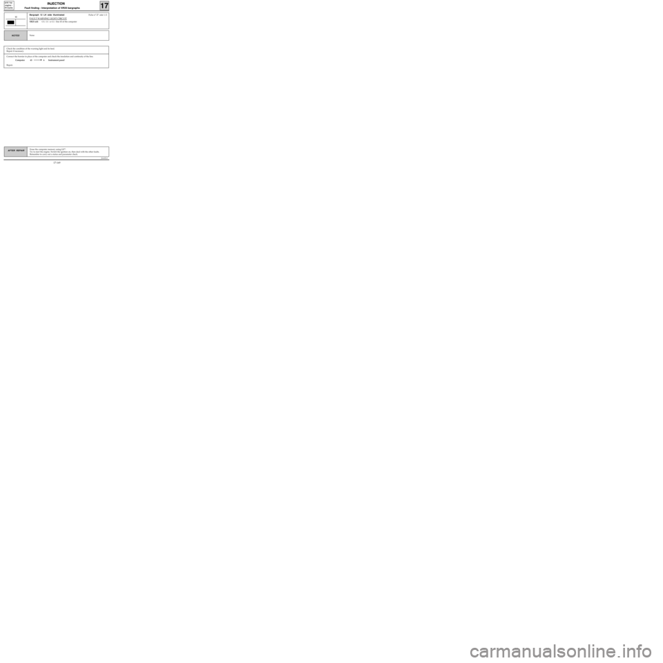
Bargraph 12 LH side illuminatedFiche n° 27 side 1/2
FAULT WARNING LIGHT CIRCUIT
XR25 aid:CO, CC- or CC+ line 43 of the computer
12
NoneNOTES
Check the condition of the warning light and its feed.
Repair if necessary.
17-169
Page 216 of 363
JSA052.0
INJECTION
Fault finding - Interpretation of XR25 bargraphs17
D7F 710
engine -
55 tracks
Erase the computer memory using G0**.
Try to start the engine. Switch the ignition on, then deal with the other faults.
Remember to carry out a status and parameter check.AFTER REPAIR
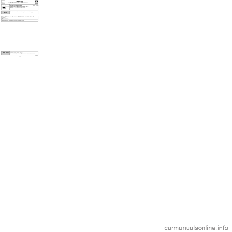
Bargraph 15 LH side illuminated Fiche n° 27 side 1/
COMPUTER AC CONNECTION CIRCUIT
XR25 aid:CC + 12 V line 51 of the computer
15
Connect the bornier in place of the computer and check the insulation and continuity of line 51 of the
computer.
Repair if necessary.
Check that the vehicle has air conditioning, if not, ignore this bargraph.NOTES
If the fault persists, consult the air conditioning fault finding section.
17-173
Page 222 of 363
JSA052.0
INJECTION
Fault finding - Status and parameter checks
17
D7F 710
engine -
55 tracks
Order of
operationsFunction to be
checkedAction Bargraph Display and notes Fault finding
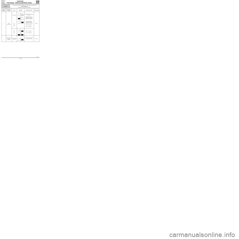
8Air
conditioningAC selected
# 06
# 44
# 06
# 44Extinguished if fast idle is
not active
Illuminated if the air
conditioning requests
compressor operation
Illuminated if the
injection authorises
compressor operation
690 ≤ X ≤ 790 rpm
300 ≤ X ≤ 4000 W
800 ≤ X ≤ 900 rpm
300 ≤ X ≤ 4000 W
DIAG 16
9Power assisted
steering
prestostatTurn wheels
to full lockIlluminated when wheels
turned to full lockDIAG 18
Carry out the actions below (engine warm, at idle speed, no consumers)
if the engine starts.
Otherwise refer to the previous pages.
NOTES
10
10
9
13
10
9
17-179
Page 228 of 363
Check the insulation, continuity and that there is no interference resistance on the electrical line :
Computer 33 B Flywheel signal sensor
Computer 34 A Flywheel signal sensor
Repair.
JSA052.0
INJECTION
Fault finding - Status and parameter interpretation17
D7F 710
engine -
55 tracks
AFTER REPAIRStart the status and parameter check again from the beginning.
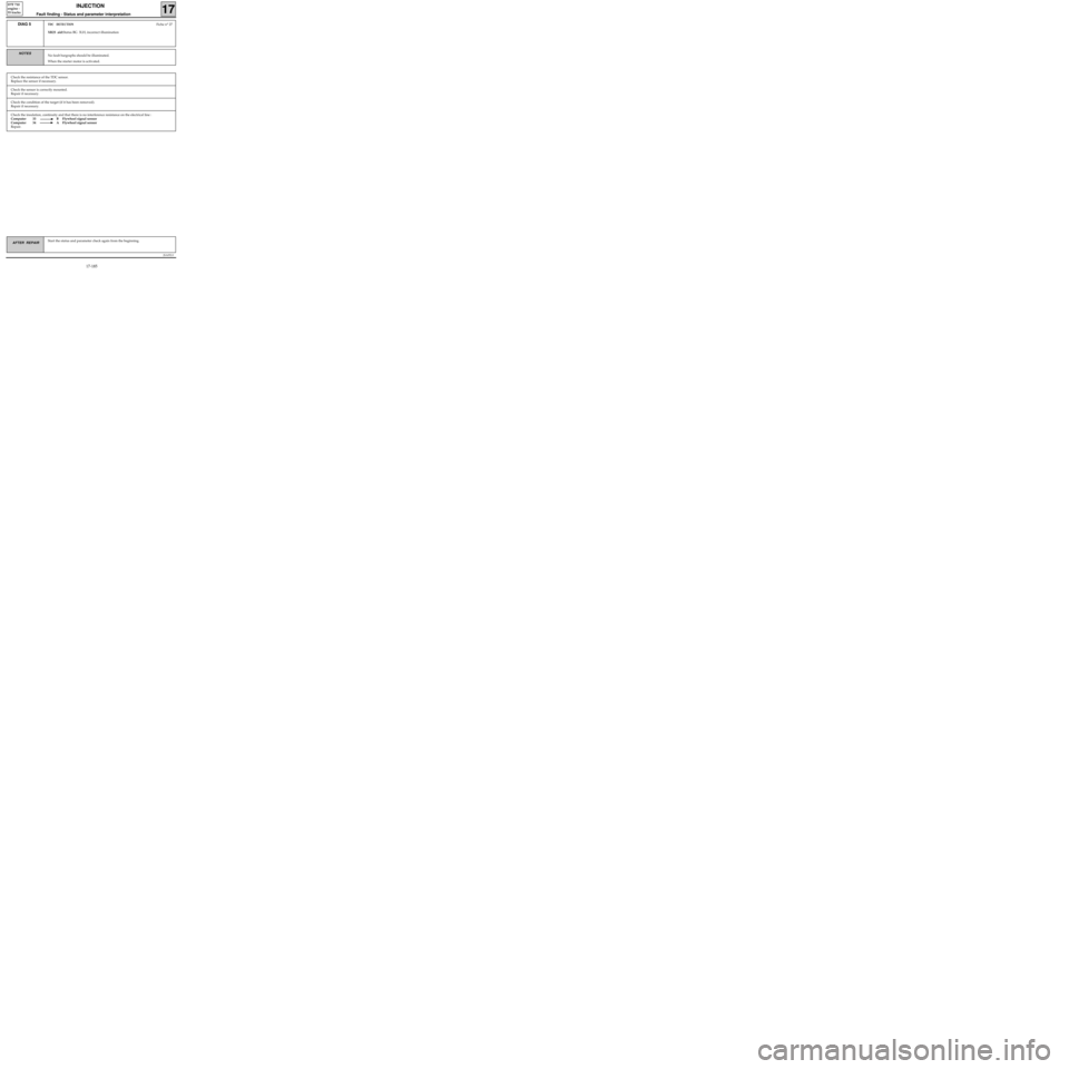
DIAG 5TDC DETECTIONFiche n° 27
XR25 aid:Status BG 3LH, incorrect illumination
No fault bargraphs should be illuminated.
When the starter motor is activated.NOTES
Check the resistance of the TDC sensor.
Replace the sensor if necessary.
Check the sensor is correctly mounted.
Repair if necessary.
Check the condition of the target (if it has been removed).
Repair if necessary.
17-185
Page 240 of 363
JSA052.0
INJECTION
Fault finding - Status and parameter interpretation17
D7F 710
engine -
55 tracks
AFTER REPAIRStart the status and parameter check again from the beginning.
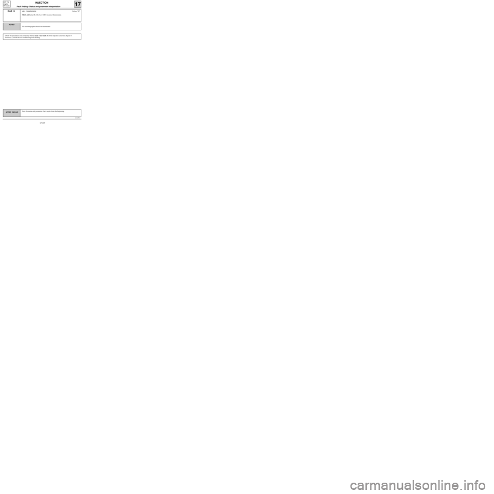
DIAG 16AIR CONDITIONINGFiche n° 27
XR25 aid:Status BG 10LH or 10RH incorrect illumination
No fault bargraphs should be illuminated.
NOTES
Check the insulation and continuity of lines track 5 and track 51 of the injection computer.Repair if
necessary.Consult the air conditioning fault finding.
17-197
Page 243 of 363
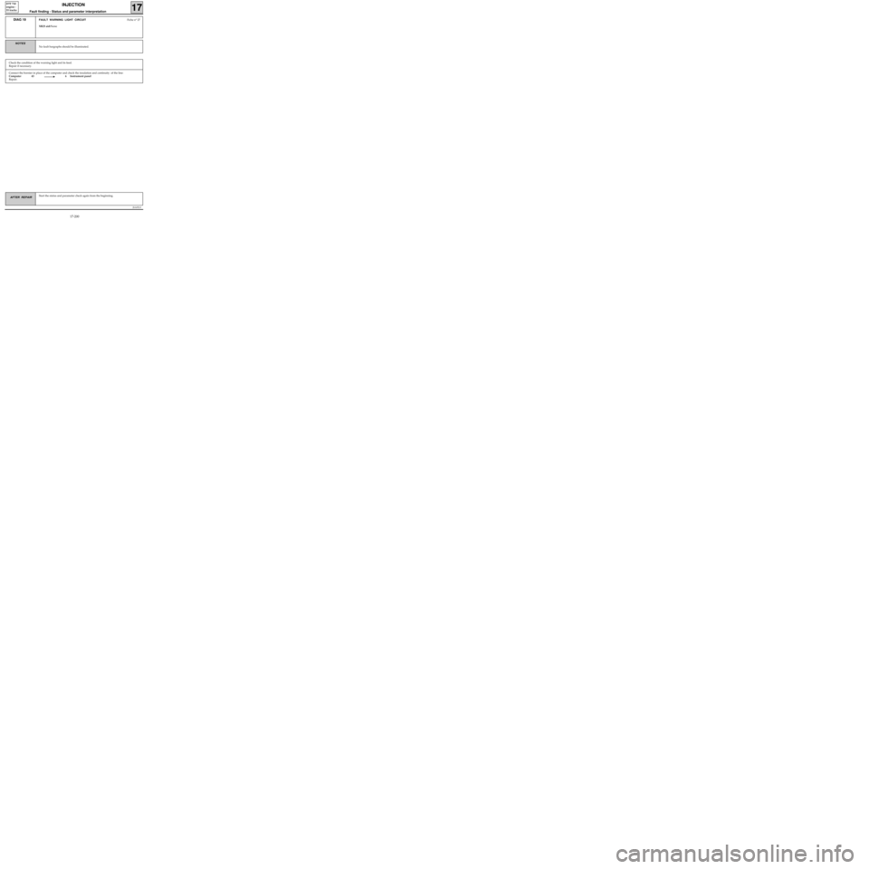
Connect the bornier in place of the computer and check the insulation and continuity of the line:
Computer 43 6 Instrument panel
Repair.
JSA052.0
INJECTION
Fault finding - Status and parameter interpretation17
D7F 710
engine -
55 tracks
AFTER REPAIRStart the status and parameter check again from the beginning.
DIAG 19FAULT WARNING LIGHT CIRCUITFiche n° 27
XR25 aid:None
No fault bargraphs should be illuminated.
NOTES
Check the condition of the warning light and its feed.
Repair if necessary.
17-200
Page 246 of 363
JSA052.0
INJECTION
Fault finding - Fault charts
17
D7F 710
engine -
55 tracks
AFTER REPAIR
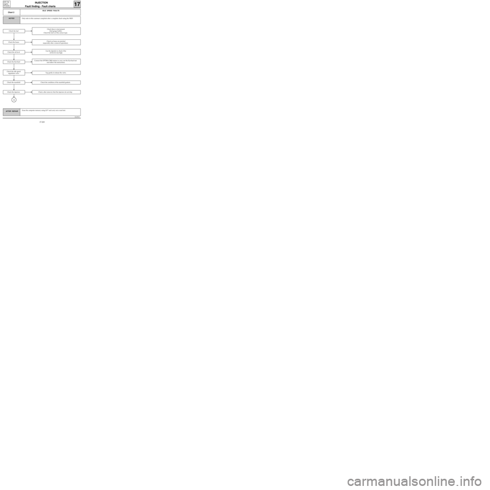
Chart 2
IDLE SPEED FAULTS
Only refer to this customer complaint after a complete check using the XR25.NOTES
Erase the computer memory using G0** and carry out a road test.
Check there is fuel present
(fuel gauge faulty).
Check the fuel is of the correct type.
Check the hosesCheck no hoses are pinched
(especially after a removal operation).
Check the oil levelUse the dipstick to check if the
oil level is too high.
Check the fuel
Check the flywheelConnect the OPTIMA 5800 station to carry out the flywheel test
and follow the instructions.
Check the idle speed
regulation valveTap gently to release the valve.
Check the manifoldCheck the condition of the manifold gaskets.
Check the injectorsCheck, after removal, that the injectors do not drip.
A
17-203