air condition RENAULT KANGOO 1997 KC / 1.G Foult Finding - Injection Service Manual
[x] Cancel search | Manufacturer: RENAULT, Model Year: 1997, Model line: KANGOO, Model: RENAULT KANGOO 1997 KC / 1.GPages: 363
Page 132 of 363
Connect the bornier in place of the computer and check the insulation and continuity of the line:
Computer 22 C Oxygen sensor
Repair if necessary.
JSA051.0
INJECTION
Fault finding - Interpretation of XR25 bargraphs17
D7F 710
engine -
35 tracks
Turn the engine, switch the ignition on and erase the computer memory using
G0**. Try to start the engine. Switch the ignition on, then deal with the other
faults. Remember to carry out a status and parameter check.AFTER REPAIR
Bargraph 3 RH side illuminated or flashingFiche n° 27 side 1/2
OXYGEN SENSOR CIRCUIT
XR25 aid:CO, CC- or CC+line 22
CO line 4
3
If BG 3RH is flashing, increase the engine speed to 2500 rpm for 5 minutes
If BG 3RH becomes permanently illuminated, deal with the fault.
NOTES
Check the connection and the condition of the connector on the oxygen sensor.
Check, ignition on during the timed phase, for :
-earth on track B of the oxygen sensor,
-+ 12 V after the fuel pump relay on track A of the oxygen sensor.
Repair if necessary.
Check for the presence of earth on track 4 on the injection computer.
Repair if necessary.
The fault persists. Replace the oxygen sensor.
The fault persists! Replace the injection computer.
IMPORTANT: The computer has probably been damaged by an electric shock. The cause of the damage
must be found before fitting a new computer.
17-87
Page 136 of 363
Connect the bornier in place of the computer and check the insulation,
continuity and that there is no interference resistance on the line:
Computer 13 B Target sensor
Computer 31 A Target sensor
Repair if necessary.
JSA051.0
INJECTION
Fault finding - Interpretation of XR25 bargraphs17
D7F 710
engine -
35 tracks
Erase the computer memory using G0**.
Try to start the engine. Switch the ignition on, then deal with the other faults.
Remember to carry out a status and parameter check.AFTER REPAIR
Bargraph 5 RH side illuminated or flashingFiche n° 27 side 1/2
FLYWHEEL SIGNAL CIRCUIT
XR25 aid:*25 = CO.0 =>CO or CC- line 13 or 31
*25 = CC.0 =
>CC- line 13 or 31 on the computer
*25 = In =
>sensor incorrectly connected
5
Try to illuminate BG 5RH when the starter is activated.
BG 5RH often seen to flash if *25 = dEF as its permanent illumination is very quick.
In certain cases, BG 5RH may illuminate then extinguish.
NOTES
Check the resistance of the target sensor.
Replace the sensor if necessary.*25 = CO.0
*25 = CC.0
Check the condition of the flywheel, especially if it has been removed.
The fault persists! Replace the injection computer.
IMPORTANT: The computer has probably been damaged by an electric shock.
The cause of the damage must be found before fitting a new
computer.
Check the target sensor has been correctly connected (the sensor connector must
not be inverted).
Repair if necessary.*25 = In
The fault persists! Replace the sensor.
17-91
Page 142 of 363
Connect the bornier in place of the computer and check the insulation and continuity of the line:
Computer 19 6 Instrument panel
Repair.
JSA051.0
INJECTION
Fault finding - Interpretation of XR25 bargraphs17
D7F 710
engine -
35 tracks
Erase the computer memory using G0**.
Try to start the engine. Switch the ignition on, then deal with the other faults.
Remember to carry out a status and parameter check.AFTER REPAIR
Bargraph 12 LH side illuminatedFiche n° 27 side 1/2
FAULT WARNING LIGHT CIRCUIT
XR25 aid:CO, CC- or CC+ line 19 of the computer
12
NoneNOTES
Check the condition of the warning light and its feed.
Repair if necessary.
17-97
Page 158 of 363
Check the insulation, continuity and that there is no interference resistance on the electrical line :
Computer 13 B Flywheel signal sensor
Computer 31 A Flywheel signal sensor
Repair.
JSA051.0
INJECTION
Fault finding - Status and parameter interpretation17
D7F 710
engine -
35 tracks
AFTER REPAIRStart the status and parameter check again from the beginning.
DIAG 5
Fiche n° 27
TDC DETECTION
XR25 aid:Status BG 3LH, incorrect illumination
No fault bargraphs should be illuminated.
When the starter motor is activated.NOTES
Check the resistance of the TDC sensor.
Replace the sensor if necessary.
Check the sensor is correctly mounted.
Repair if necessary.
Check the condition of the target (if it has been removed).
Repair if necessary.
17-113
Page 172 of 363
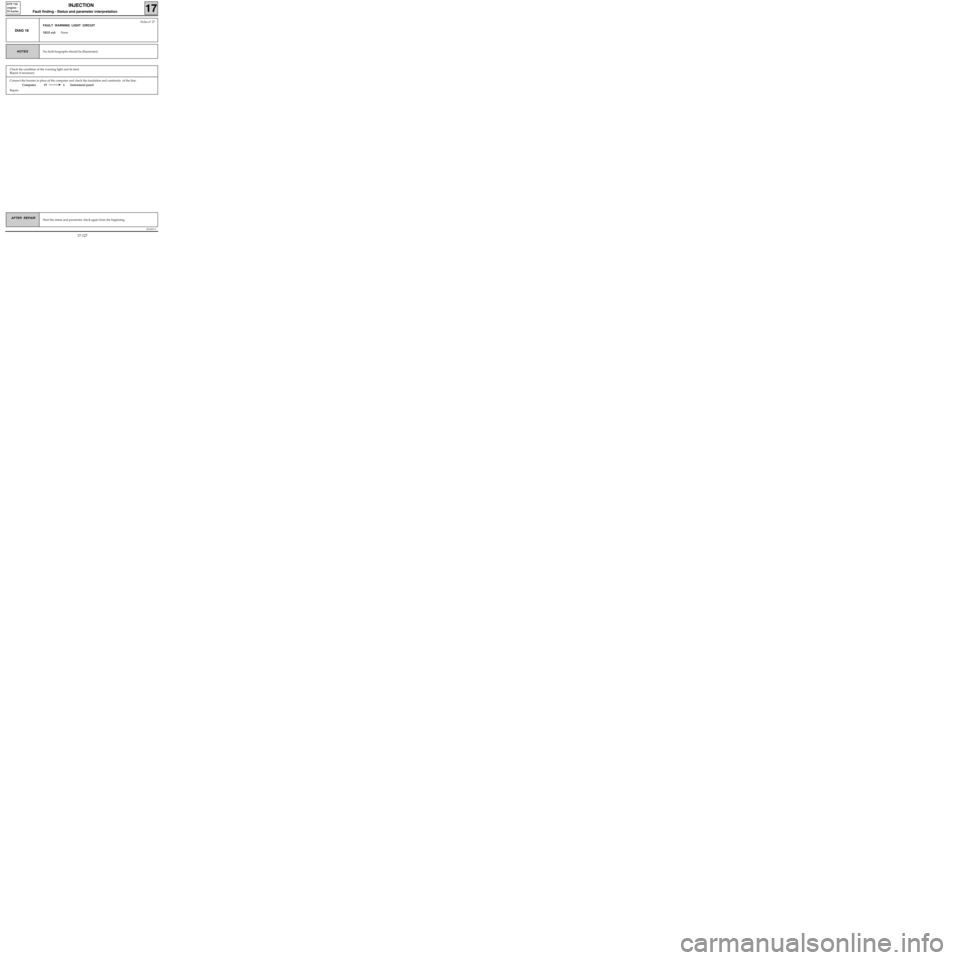
Connect the bornier in place of the computer and check the insulation and continuity of the line:
Computer 19 6 Instrument panel
Repair.
JSA051.0
INJECTION
Fault finding - Status and parameter interpretation17
D7F 710
engine -
35 tracks
AFTER REPAIRStart the status and parameter check again from the beginning.
DIAG 18
Fiche n° 27
FAULT WARNING LIGHT CIRCUIT
XR25 aid:None
No fault bargraphs should be illuminated.NOTES
Check the condition of the warning light and its feed.
Repair if necessary.
17-127
Page 175 of 363
JSA051.0
INJECTION
Fault finding - Fault charts
17
D7F 710
engine -
35 tracks
AFTER REPAIR
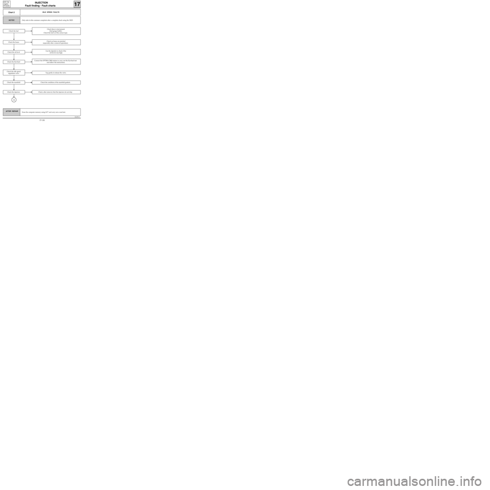
Chart 2IDLE SPEED FAULTS
Only refer to this customer complaint after a complete check using the XR25.NOTES
Erase the computer memory using G0** and carry out a road test.
Check there is fuel present
(fuel gauge faulty).
Check the fuel is of the correct type.
Check the hosesCheck no hoses are pinched
(especially after a removal operation).
Check the oil levelUse the dipstick to check if the
oil level is too high.
Check the fuel
Check the flywheelConnect the OPTIMA 5800 station to carry out the flywheel test
and follow the instructions.
Check the idle speed
regulation valveTap gently to release the valve.
Check the manifoldCheck the condition of the manifold gaskets.
Check the injectorsCheck, after removal, that the injectors do not drip.
A
17-130
Page 177 of 363
JSA051.0
INJECTION
Fault finding - Fault charts
17
D7F 710
engine -
35 tracks
AFTER REPAIRErase the computer memory using G0** and carry out a road test.
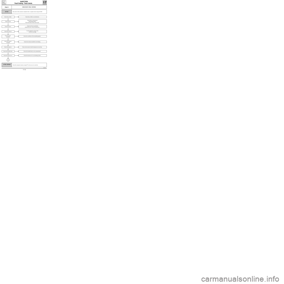
Chart 3BEHAVIOUR WHILE DRIVING
Only refer to this customer complaint after a complete check using the XR25.NOTES
Check the air filter is not deformed.
Check the fuel
Check there is fuel present
(fuel gauge faulty).
Check the fuel is of the correct type.
Check the hosesCheck no hoses are pinched
(especially after a removal operation).
Check the air filter
Check the oil levelUse the dipstick to check if the
oil level is too high.
Check the condition of the manifold gaskets.Check the inlet
manifold
Check the exhaust manifold is not leaking.Check the exhaust
manifold
Check, after removal, that the injectors do not drip.Check the injectors
Check the throttle body is not contaminated.Check the throttle body
Check the brake servo is not leaking (noise).Check the brake servo
A
17-132
Page 192 of 363
JSA052.0
INJECTION
Fault finding - Introduction
17
D7F 710
engine -
55 tracks
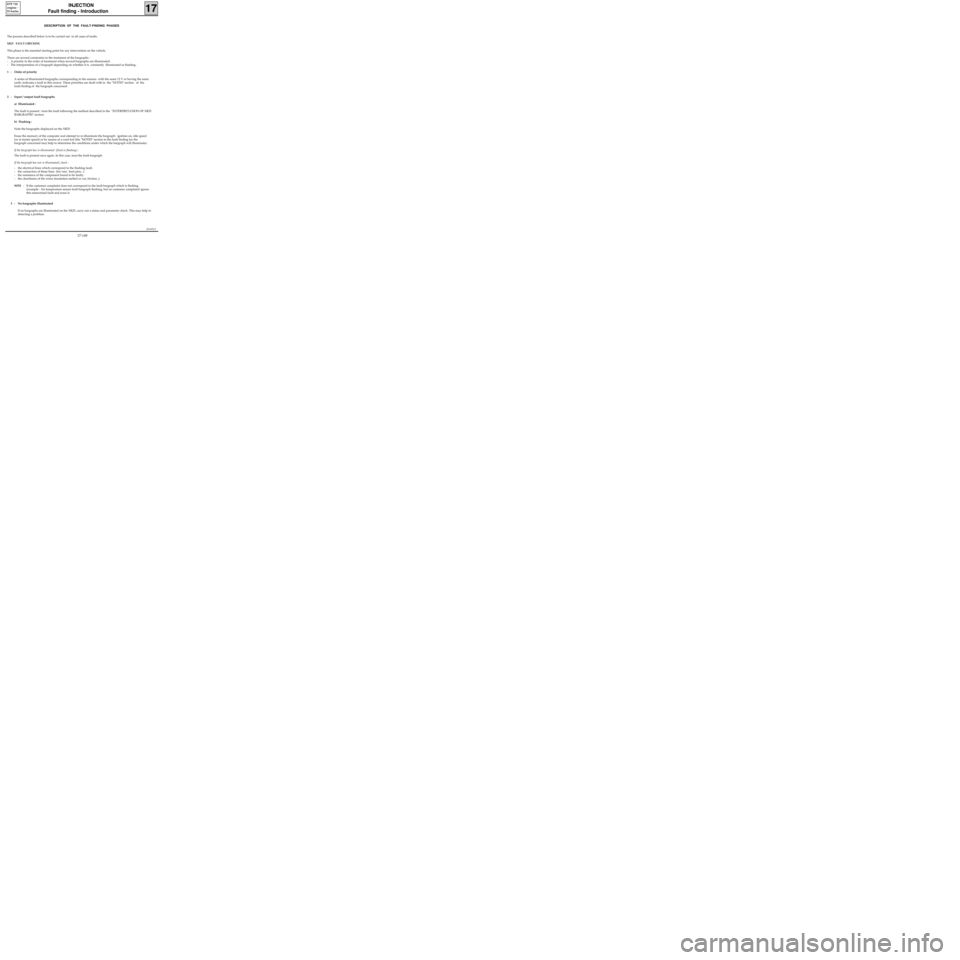
DESCRIPTION OF THE FAULT-FINDING PHASES
The process described below is to be carried out in all cases of faults.
XR25 FAULT-CHECKING
This phase is the essential starting point for any intervention on the vehicle.
There are several constraints to the treatment of the bargraphs :
- A priority in the order of treatment when several bargraphs are illuminated.
- The interpretation of a bargraph depending on whether it is constantly illuminated or flashing .
1 - Order of priority
A series of illuminated bargraphs corresponding to the sensors with the same 12 V or having the same
earth, indicates a fault in this source. These priorities are dealt with in the "NOTES" section of the
fault-finding of the bargraph concerned.
2 - Input / output fault bargraphs
a) Illuminated :
The fault is present : treat the fault following the method described in the "INTERPRETATION OF XR25
BARGRAPHS" section.
b) Flashing :
Note the bargraphs displayed on the XR25.
Erase the memory of the computer and attempt to re-illuminate the bargraph: ignition on, idle speed
(or at starter speed) or by means of a road test (the "NOTES" section in the fault finding for the
bargraph concerned may help to determine the conditions under which the bargraph will illuminate).
If the bargraph has re-illuminated (fixed or flashing) :
The fault is present once again. In this case, treat the fault bargraph.
If the bargraph has not re-illuminated, check :
- the electrical lines which correspond to the flashing fault,
- the connectors of these lines (for rust, bent pins...).
- the resistance of the component found to be faulty.
- the cleanliness of the wires (insulation melted or cut, friction..).
NOTE : If the customer complaint does not correspond to the fault bargraph which is flashing
(example : Air temperature sensor fault bargraph flashing, but no customer complaint) ignore
this memorised fault and erase it.
3 - No bargraphs illuminated
If no bargraphs are illuminated on the XR25, carry out a status and parameter check. This may help in
detecting a problem.
17-149
Page 193 of 363

JSA052.0
INJECTION
Fault finding - Introduction
17
D7F 710
engine -
55 tracks
XR25 CHECKING STATUSES AND PARAMETERS
The status and parameter check is aimed at checking the statuses and parameters which do not illuminate
any fault bargraphs if they are outside of permitted tolerance values . This phase allows :
- Faults to be found without the illumination of fault bargraphs which may correspond to a customer
complaint (example : absence of no load information causing an unstable idle speed).
- The correct operation of the injection to be checked and the risk of faults appearing shortly after the
repair to be eliminated.
This section contains fault-finding for statuses and parameters, under their test conditions
(example : fault finding for # 01 ignition on and fault finding for # 01 engine running).
If a status does not operate normally or a parameter is outside of permitted tolerance values, consult the
fault-finding page indicated in the "Fault-finding" column.
XR25 CHECK CORRECT
If the XR25 check is correct, but the customer complaint persists, the problem must be dealt with through
customer complaints.
Treatment of customer complaints
This section has fault charts, which suggest a series of possible causes of the problem.
These lines of enquiry must only be used in the following cases :
- No fault bargraph appears on the XR25.
- No faults are detected during the checking of statuses and parameters.
- The vehicle is not operating correctly
POST-REPAIR CHECK
This operation is a simple check of the repair (by a command, or by an XR25 command mode ...).
This makes it possible to check that the system upon which the intervention has been carried out is correct
electrically.
It is an introduction to the road test.
ROAD TEST
A road test is essential in order to guarantee the correct operation of the vehicle and to test the quality of the
repair. Its role is to make sure that no faults occur (or will occur) when driving.
In order to be significant, the road test is subject to special driving conditions.
17-150
Page 194 of 363

JSA052.0
INJECTION
Fault finding - Introduction
17
D7F 710
engine -
55 tracks
Driving conditions for programming the adaptive variables:
During the road test, the engine speed must be stabilised for a few moments between:
260 < # 01 < 385 mbars
then 385 < # 01 < 510 mbars
then 510 < # 01 < 635 mbars
then is 635 < # 01 < 760 mbars
then 760 < # 01 < 970 mbars
Do not exceed an engine speed of 4400 rpm
The engine must be warm (coolant temperature > 75 °C).
For this test, start from a fairly low engine speed, in 3rd or 4th gear, and apply progressive acceleration to
stabilise at the pressure required for 10 seconds in each zone.
The test must then be continued by driving normally, in a varied manner for 3 to 6 miles (5 to 10 km).
17-151