compression ratio RENAULT KANGOO 1997 KC / 1.G Foult Finding - Injection Workshop Manual
[x] Cancel search | Manufacturer: RENAULT, Model Year: 1997, Model line: KANGOO, Model: RENAULT KANGOO 1997 KC / 1.GPages: 363
Page 45 of 363
DPCF01 1.0
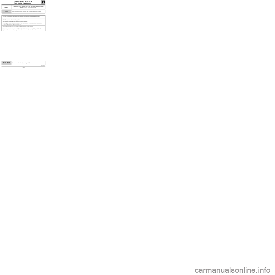
LUCAS DIESEL INJECTION
Fault finding - Fault charts
13
Carry out a road test then check using the XR25.AFTER REPAIR
If the fault persists, check the fuel supply circuits (for the pump and the injectors).
If necessary, carry out a complete check of the engine (starter drive speed, pump timing, condition of
injectors, rocker arm clearances, compression, .....).NOTES
Chart 4STARTING FAULT (ENGINE WILL NOT START OR IS DIFFICULT TO
START) (warning light extinguished).
Only consult this customer complaint after a complete check using the XR25.
If no fault is shown by the XR25, ensure that the fault is not caused by a faulty immobiliser system.
Check the operation of the preheating system:
Start command mode G10*1* and check for a voltage at the plugs.
If the plugs are not fed, check the connection of the 3 track connector on the relay unit and the condition
of the 70 Amp fuse on the engine connection unit.
13-41
Page 80 of 363
JF5111.0
INJECTION
Fault finding - Status and parameter checks
17
E7J 780
engine
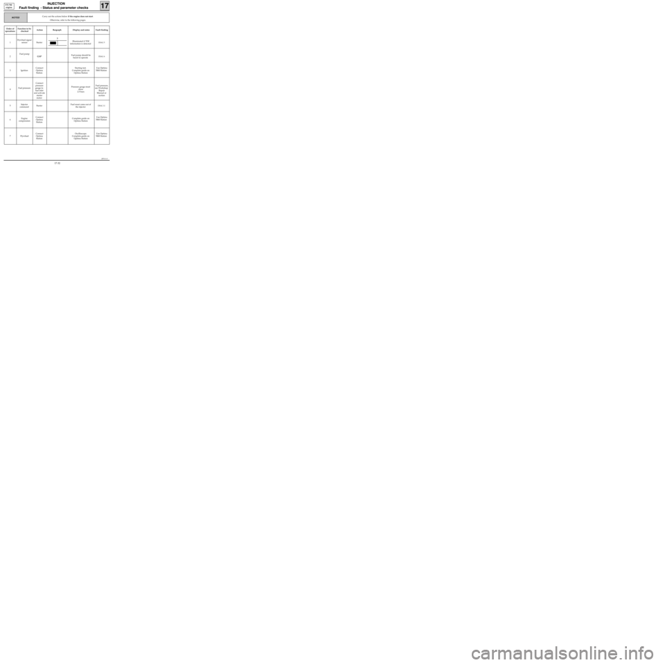
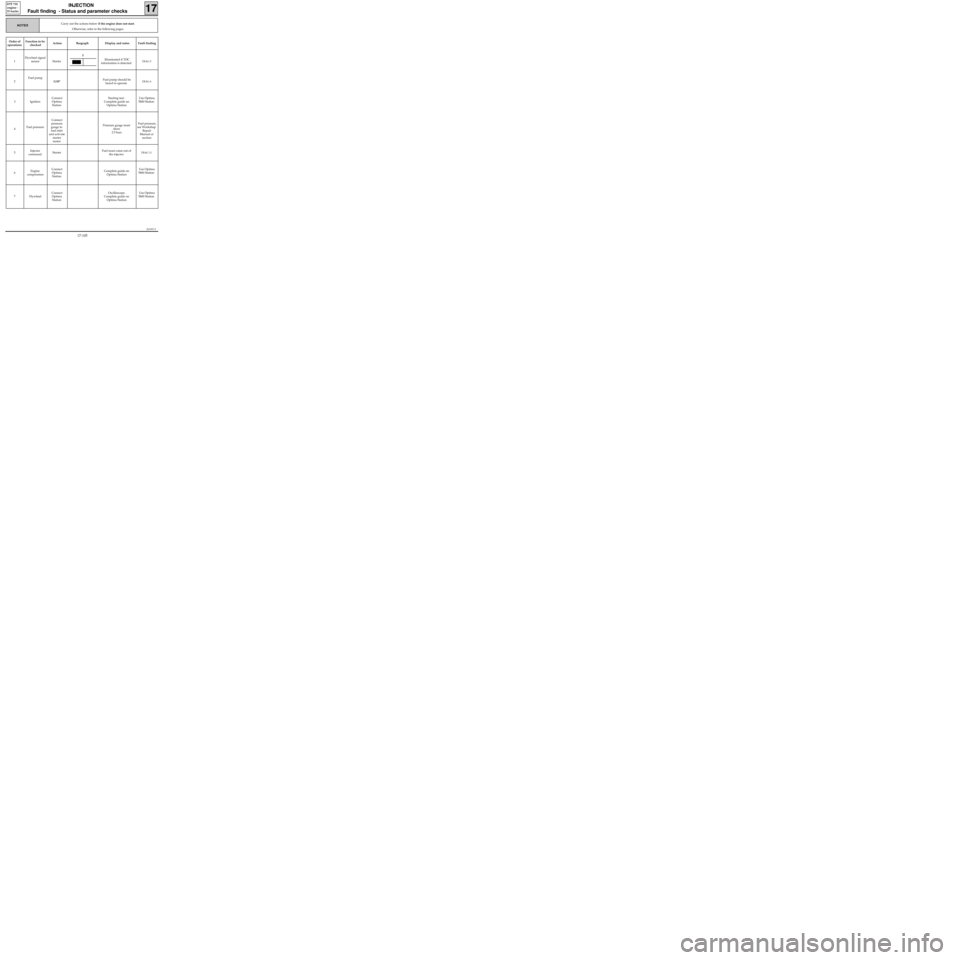
Carry out the actions below if the engine does not start.
Otherwise, refer to the following pages.NOTES
Order of
operationsFunction to be
checkedAction Bargraph Display and notes Fault finding
1Flywheel signal
sensor StarterIlluminated if TDC
information is detected
DIAG 5
2Fuel pump
G10*Fuel pump should be
heard to operateDIAG 6
3 IgnitionConnect
Optima
StationStarting test.
Complete guide on
Optima StationUse Optima
5800 Station
4Fuel pressureConnect
pressure
gauge to
fuel inlet
and activate
starter
motorPressure gauge must
show
2.5 bars Fuel pressure,
see Workshop
Repair
Manual or
section
5Injector
commandStarterFuel must come out of
the injector
DIAG 11
6Engine
compressionConnect
Optima
StationComplete guide on
Optima StationUse Optima
5800 Station
7 FlywheelConnect
Optima
StationOscilloscope.
Complete guide on
Optima StationUse Optima
5800 Station
3
17-32
Page 92 of 363
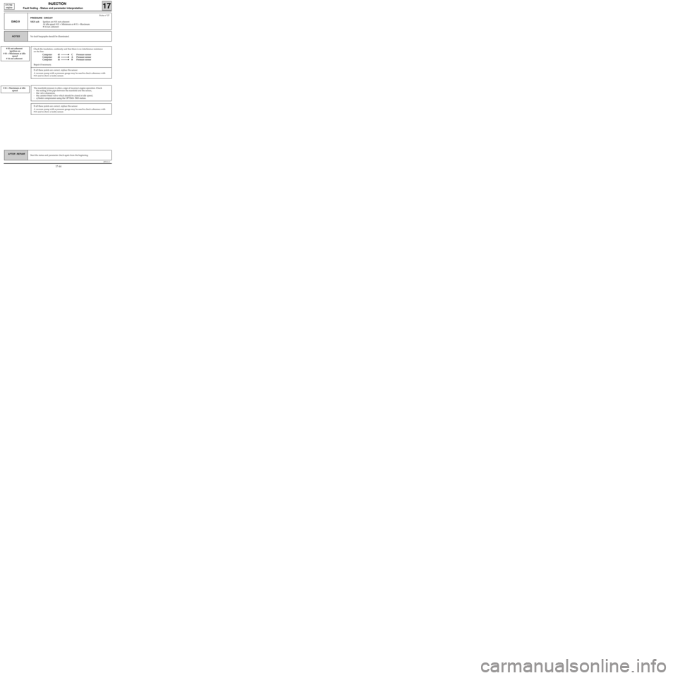
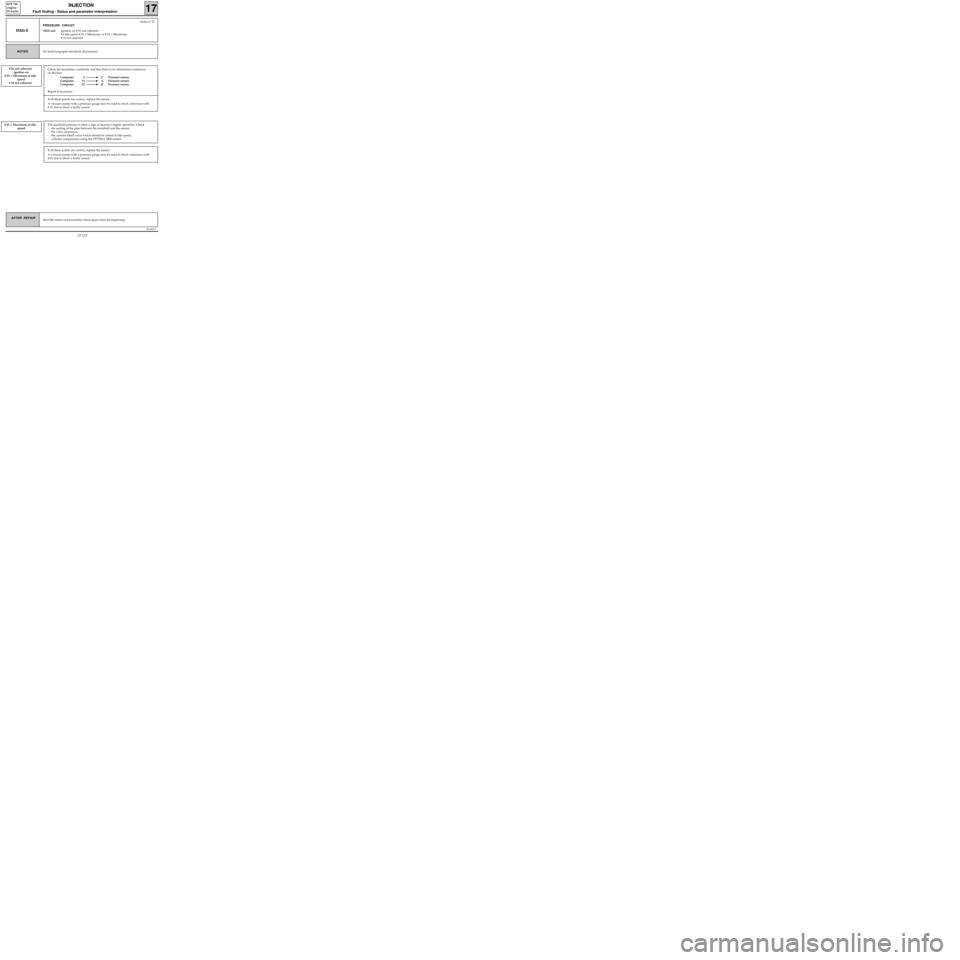
Check the insulation, continuity and that there is no interference resistance
on the line:
Computer 45 C Pressure sensor
Computer 44 A Pressure sensor
Computer 16 B Pressure sensor
Repair if necessary.
JF5111.0
INJECTION
Fault finding - Status and parameter interpretation17
E7J 780
engine
AFTER REPAIRStart the status and parameter check again from the beginning.
DIAG 9
Fiche n° 27
PRESSURE CIRCUIT
XR25 aid:Ignition on # 01 not coherent
At idle speed # 01 < Minimum or # 01 > Maximum
# 16 not coherent
No fault bargraphs should be illuminated.NOTES
# 01 not coherent
ignition on
# 01 < Minimum at idle
speed
# 16 not coherent
If all these points are correct, replace the sensor.
A vacuum pump with a pressure gauge may be used to check coherence with
# 01 and to show a faulty sensor.
# 01 > Maximum at idle
speedThe manifold pressure is often a sign of incorrect engine operation. Check
- the sealing of the pipe between the manifold and the sensor,
- the valve clearances,
- the canister bleed valve which should be closed at idle speed,
- cylinder compression using the OPTIMA 5800 station.
If all these points are correct, replace the sensor.
A vacuum pump with a pressure gauge may be used to check coherence with
# 01 and to show a faulty sensor.
17-44
Page 105 of 363
JF5111.0
INJECTION
Fault finding - Fault charts
17
E7J 780
engine
AFTER REPAIR
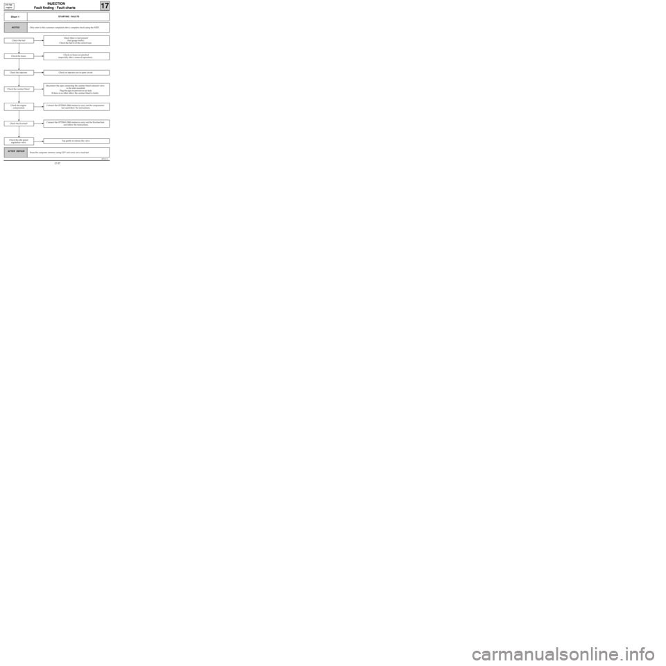
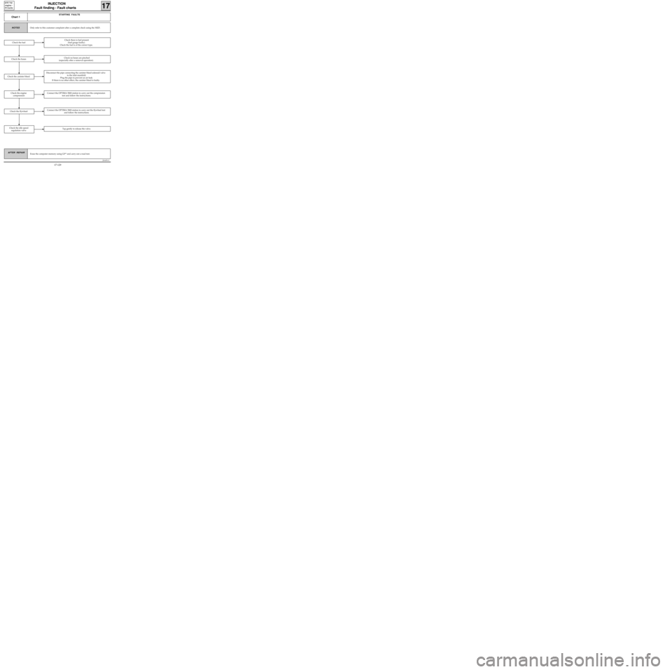
Chart 1STARTING FAULTS
Only refer to this customer complaint after a complete check using the XR25.NOTES
Erase the computer memory using G0** and carry out a road test.
Check there is fuel present
(fuel gauge faulty).
Check the fuel is of the correct type.
Check the hosesCheck no hoses are pinched
(especially after a removal operation).
Disconnect the pipe connecting the canister bleed solenoid valve
to the inlet manifold.
Plug the pipe to prevent an air leak.
If there is no other effect, the canister bleed is faulty.
Check the fuel
Connect the OPTIMA 5800 station to carry out the compression
test and follow the instructions.
Connect the OPTIMA 5800 station to carry out the flywheel test
and follow the instructions.
Check the idle speed
regulation valveTap gently to release the valve.
Check the flywheel
Check the engine
compression
Check the canister bleed
Check the injectorsCheck no injectors are in open circuit.
17-57
Page 150 of 363
Order of
operationsFunction to be
checkedAction Bargraph Display and notes Fault finding
1Flywheel signal
sensor StarterIlluminated if TDC
information is detected
DIAG 5
2Fuel pump
G10*Fuel pump should be
heard to operateDIAG 6
3 IgnitionConnect
Optima
StationStarting test.
Complete guide on
Optima StationUse Optima
5800 Station
4Fuel pressureConnect
pressure
gauge to
fuel inlet
and activate
starter
motorPressure gauge must
show
2.5 bars Fuel pressure,
see Workshop
Repair
Manual or
section
5Injector
commandStarterFuel must come out of
the injector
DIAG 11
6Engine
compressionConnect
Optima
StationComplete guide on
Optima StationUse Optima
5800 Station
7 FlywheelConnect
Optima
StationOscilloscope.
Complete guide on
Optima StationUse Optima
5800 Station
JSA051.0
INJECTION
Fault finding - Status and parameter checks
17
D7F 710
engine -
35 tracks
Carry out the actions below if the engine does not start.
Otherwise, refer to the following pages.NOTES
3
17-105
Page 162 of 363
Check the insulation, continuity and that there is no interference resistance
on the line:
Computer 5 C Pressure sensor
Computer 15 A Pressure sensor
Computer 23 B Pressure sensor
Repair if necessary.
JSA052.0
INJECTION
Fault finding - Status and parameter interpretation17
D7F 710
engine -
35 tracks
AFTER REPAIRStart the status and parameter check again from the beginning.
DIAG 9
Fiche n° 27
PRESSURE CIRCUIT
XR25 aid:Ignition on # 01 not coherent
At idle speed # 01 < Minimum or # 01 > Maximum
# 16 not coherent
No fault bargraphs should be illuminated.NOTES
# 01 not coherent
ignition on
# 01 < Minimum at idle
speed
# 16 not coherent
If all these points are correct, replace the sensor.
A vacuum pump with a pressure gauge may be used to check coherence with
# 01 and to show a faulty sensor.
# 01 > Maximum at idle
speedThe manifold pressure is often a sign of incorrect engine operation. Check
- the sealing of the pipe between the manifold and the sensor,
- the valve clearances,
- the canister bleed valve which should be closed at idle speed,
- cylinder compression using the OPTIMA 5800 station.
If all these points are correct, replace the sensor.
A vacuum pump with a pressure gauge may be used to check coherence with
# 01 and to show a faulty sensor.
17-117
Page 174 of 363
JSA051.0
INJECTION
Fault finding - Fault charts
17
D7F 710
engine -
35 tracks
AFTER REPAIR
Chart 1
STARTING FAULTS
Only refer to this customer complaint after a complete check using the XR25.NOTES
Erase the computer memory using G0** and carry out a road test.
Check there is fuel present
(fuel gauge faulty).
Check the fuel is of the correct type.
Check the hosesCheck no hoses are pinched
(especially after a removal operation).
Disconnect the pipe connecting the canister bleed solenoid valve
to the inlet manifold.
Plug the pipe to prevent an air leak.
If there is no other effect, the canister bleed is faulty.
Check the fuel
Connect the OPTIMA 5800 station to carry out the compression
test and follow the instructions.
Connect the OPTIMA 5800 station to carry out the flywheel test
and follow the instructions.
Check the idle speed
regulation valveTap gently to release the valve.
Check the flywheel
Check the engine
compression
Check the canister bleed
17-129
Page 220 of 363
JSA052.0
INJECTION
Fault finding - Status and parameter checks
17
D7F 710
engine -
55 tracks
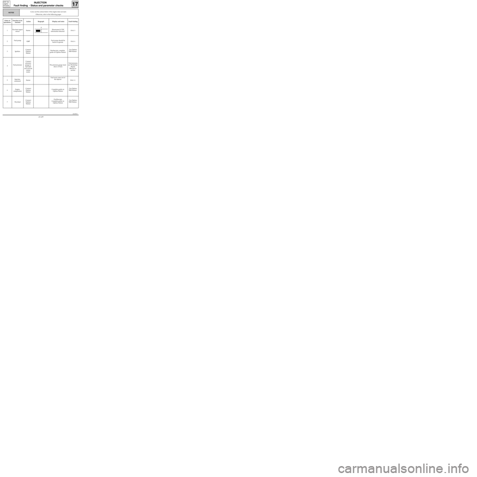
Carry out the actions below if the engine does not start.
Otherwise, refer to the following pages.NOTES
Order of
operationsFunction to be
checkedAction Bargraph Display and notes Fault finding
1Flywheel signal
sensorStarterIlluminated if TDC
information detected
DIAG 5
2Fuel pump
G10*Fuel pump should be
heard to operateDIAG 6
3 IgnitionConnect
Optima
StationStarting test, complete
guide on Optima StationUse Optima
5800 Station
4Fuel pressureConnect
pressure
gauge to
fuel inlet
and activate
starter
motorThe pressure gauge must
show 2.5 bars Fuel pressure,
see Workshop
Repair
Manual or
section
5Injection
commandStarterFuel must come out of
the injector
DIAG 11
6Engine
compressionConnect
Optima
StationComplete guide on
Optima StationUse Optima
5800 Station
7 FlywheelConnect
Optima
StationOscilloscope.
Complete guide on
Optima StationUse Optima
5800 Station
3
17-177
Page 232 of 363
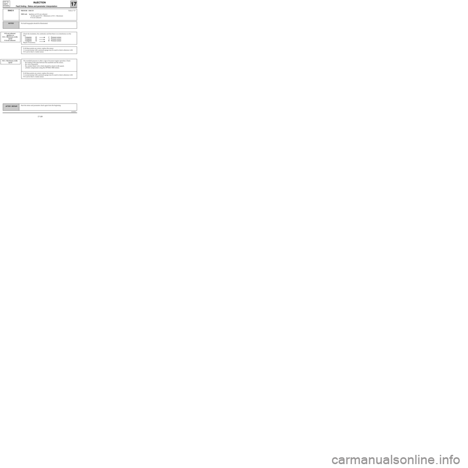
Check the insulation, the continuity and that there is no interference on the
line:
Computer 45 C Pressure sensor
Computer 44 A Pressure sensor
Computer 16 B Pressure sensor
Repair if necessary.
JSA052.0
INJECTION
Fault finding - Status and parameter interpretation17
D7F 710
engine -
55 tracks
AFTER REPAIRStart the status and parameter check again from the beginning.
DIAG 9PRESSURE CIRCUITFiche n° 27
XR25 aid: Ignition on # 01 not coherent
At idle speed # 01 < Minimum or # 01 > Maximum
# 16 not coherent
No fault bargraphs should be illuminated.NOTES
# 01 not coherent
ignition on
# 01 < Minimum at idle
speed
# 16 not coherent
If all these points are correct, replace the sensor.
A vacuum pump with a pressure gauge may be used to check coherence with
# 01 and to show a faulty sensor.
# 01 > Maximum at idle
speedThe manifold pressure is often a sign of incorrect engine operation. Check
- the sealing of the pipe between the manifold and the sensor,
- the valve clearances,
- the canister bleed valve which should be closed at idle speed,
- cylinder compression using the OPTIMA 5800 station.
If all these points are correct, replace the sensor.
A vacuum pump with a pressure gauge may be used to check coherence with
# 01 and to show a faulty sensor.
17-189
Page 245 of 363
JSA052.0
INJECTION
Fault finding - Fault charts
17
D7F 710
engine -
55 tracks
AFTER REPAIR
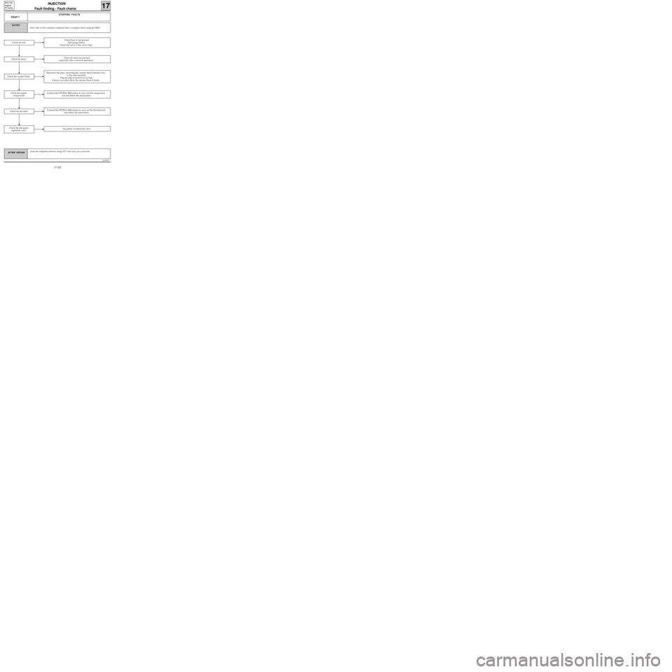
Chart 1
STARTING FAULTS
Only refer to this customer complaint after a complete check using the XR25.
NOTES
Erase the computer memory using G0** and carry out a road test.
Check there is fuel present
(fuel gauge faulty).
Check the fuel is of the correct type.
Check the hosesCheck no hoses are pinched
(especially after a removal operation).
Disconnect the pipe connecting the canister bleed solenoid valve
to the inlet manifold.
Plug the pipe to prevent an air leak.
If there is no other effect, the canister bleed is faulty.
Check the fuel
Connect the OPTIMA 5800 station to carry out the compression
test and follow the instructions.
Connect the OPTIMA 5800 station to carry out the flywheel test
and follow the instructions.
Check the idle speed
regulation valveTap gently to release the valve.
Check the flywheel
Check the engine
compression
Check the canister bleed
17-202