engine coolant RENAULT KANGOO 1997 KC / 1.G Foult Finding - Injection Workshop Manual
[x] Cancel search | Manufacturer: RENAULT, Model Year: 1997, Model line: KANGOO, Model: RENAULT KANGOO 1997 KC / 1.GPages: 363
Page 11 of 363
DPCF01 1.0
LUCAS DIESEL INJECTION
Fault finding - Interpretation of XR25 bargraphs13
AFTER REPAIRErase the computer memory (G0**), switch the ignition off, then carry out a road
test.
Finish the operation by checking using the XR25.
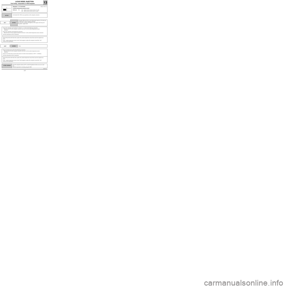
Bargraph 2 LH illuminated
Coolant temperature sensor circuit
XR25 aid:*02 :co.1 : Open circuit or short circuit to 12 volts
cc.0 : Short circuit or short circuit to earth
2
Use bornier Elé. 1332 for any operations on the computer connector.NOTES
Fiche n° 60 1/2
co.1
Ensure the continuity and insulation in relation to + 12 volts of the following connection :
- Between track 25 on the computer connector and track 2 on the coolant temperature sensor
connector.
Ensure the continuity of the following connection :
- Between track 3 on the computer connector and track 1 on the coolant temperature sensor connector.
Test the connections on the 2 connectors.
If bargraphs 2RH and 3LH are also illuminated, look for a CO of the sen-
sor earth (track 3 of the computer connector)
Also check the condition and tightness of the engine earth strap and
the gearbox engine earth.
NOTES
If the fault persists after these tests, replace the coolant temperature sensor then erase the computer me-
mory.
If the "coolant temperature sensor circuit" fault reappears, replace the computer (consult the "Aid"
section for this operation).
cc.0None NOTES
Ensure insulation from earth of the following connection :
- Between track 25 on the computer connector and track 2 on the coolant temperature sensor
connector.
Check to see if the sensor circuit (or the sensor) is in short circuit (resistance at 60°C = 1.2 Kohms).
Test the connections on the 2 connectors.
If the fault persists after these tests, replace the coolant temperature sensor then erase the computer me-
mory.
If the "coolant temperature sensor circuit" fault reappears, replace the computer (consult the "Aid"
section for this operation).
13-7
Page 37 of 363
DPCF01 1.0
LUCAS DIESEL INJECTION
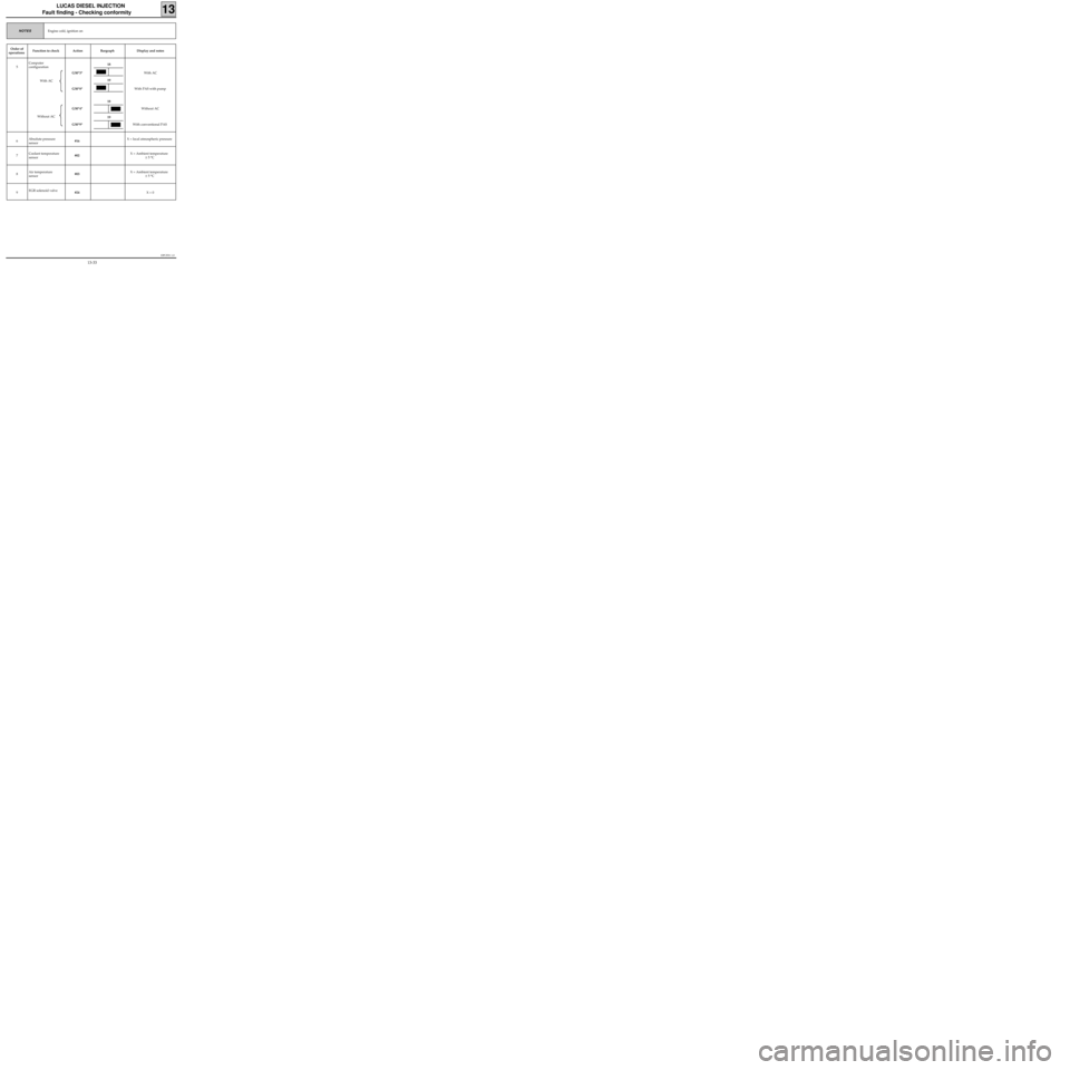
Fault finding - Checking conformity
13
Engine cold, ignition onNOTES
Order of
operationsFunction to check Action Bargraph Display and notes
5Computer
configuration
With AC
Without ACG50*3*
G50*8*
G50*4*
G50*9*With AC
With PAS with pump
Without AC
With conventional PAS
6Absolute pressure
sensor#16 X = local atmospheric pressure
7Coolant temperature
sensor#02 X = Ambient temperature
± 5 °C
8Air temperature
sensor#03 X = Ambient temperature
± 5 °C
9EGR solenoid valve
#24 X = 0
18
18
19
19
13-33
Page 53 of 363
JF5111.0
INJECTION
Fault finding - Introduction
17
E7J 780
engine
Driving conditions for programming the adaptive variables:
During the road test, the engine speed must be stabilised for a few moments between:
220 < # 01 < 340 mbars
then 340 < # 01 < 470 mbars
then 470 < # 01 < 600 mbars
then 600 < # 01 < 730 mbars
then 730 < # 01 < 870 mbars
Do not exceed an engine speed of 4800 rpm
The engine must be warm (coolant temperature > 75 °C).
For this test, start from a fairly low engine speed, in 3rd or 4th gear, and apply progressive acceleration to
stabilise at the pressure required for 10 seconds in each zone.
The test must then be continued by driving normally, in a varied manner for 3 to 6 miles (5 to 10 km).
17-5
Page 62 of 363
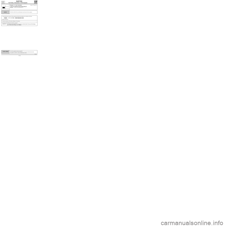
Connect the bornier in place of the computer and check the insulation and continuity of the line:
Computer 44 B1 Coolant temperature sensor
Computer 15 B2 Coolant temperature sensor
Repair if necessary.
JF5111.0
INJECTION
Fault finding - Interpretation of XR25 bargraphs17
E7J 780
engine
Erase the computer memory using G0**.
Try to start the engine. Switch the ignition on, then deal with the other faults.
Remember to carry out a status and parameter check.AFTER REPAIR
Bargraph 4 LH side illuminatedFiche n° 27 side 1/2
COOLANT TEMPERATURE SENSOR CIRCUIT
XR25 aid:CO, CC- or CC+line 44 or 15
4
If BG 6LH or BG 5LH is also illuminated, check line 44 of the computer.NOTES
The fault persists! Replace the injection computer.
IMPORTANT: The computer has probably been damaged by an electric shock. The cause of the damage
must be found before fitting a new computer.
Check the resistance of the sensor. Replace it if necessary.
17-14
Page 79 of 363
JF5111.0
INJECTION
Fault finding - Status and parameter checks
17
E7J 780
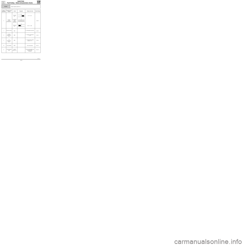
engine
Engine stopped, ignition on.NOTES
Order of
operationsFunction to be
checkedAction Bargraph Display and notes Fault finding
6Throttle
position
potentiometer
.No load
# 17
Accelerator
pedal
slightly
depressed
Full load
# 1716 < X < 50
185 < X < 243
DIAG 2
7Pressure sensor
# 01X =Atmospheric pressureDIAG 9
8Coolant
temperature
sensor# 02X = Engine temperature
± 5 °CDIAG 3
9Air
temperature
sensor# 03X = Temperature under
bonnet ± 5 °CDIAG 4
10 Fan assemblyG17*Fan must operateDIAG 17
11Fault warning
lightSwitch
ignition onFault warning light must
illuminate then
extinguishDIAG 19
2
2
2
17-31
Page 86 of 363
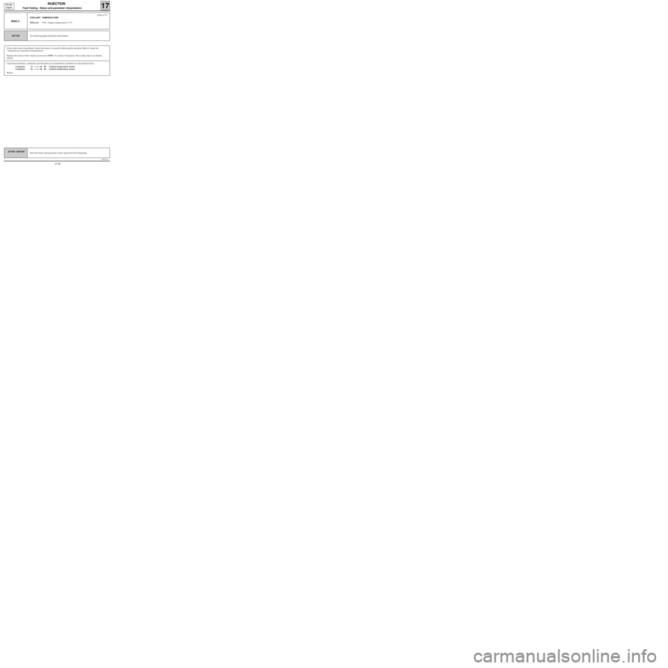
Check the insulation, continuity and that there is no interference resistance on the electrical line :
Computer 15 B2 Coolant temperature sensor
Computer 44 B1 Coolant temperature sensor
Repair.
JF5111.0
INJECTION
Fault finding - Status and parameter interpretation17
E7J 780
engine
AFTER REPAIRStart the status and parameter check again from the beginning.
DIAG 3
Fiche n° 27
COOLANT TEMPERATURE
XR25 aid: # 02 = Engine temperature ± 5 °C
No fault bargraphs should be illuminated.NOTES
If the value read is incoherent, check the sensor is correctly following the standard table of values for
"resistance as a function of temperature".
Replace the sensor if the values are incorrect (
NOTE : If a sensor is incorrect, this is often due to an electric
shock).
17-38
Page 110 of 363
JF5111.0
INJECTION
Fault finding -Aid
17
E7J 780
engine
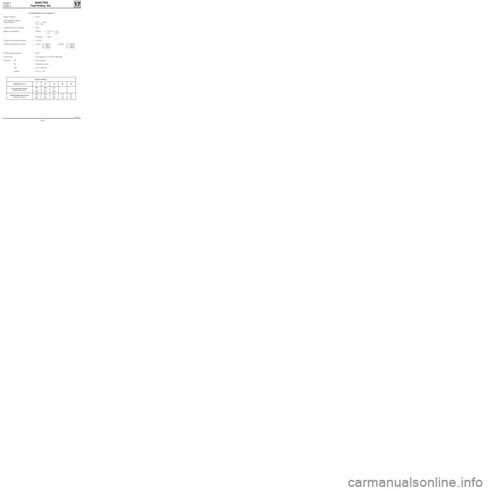
For further details, refer to section 12
Injector resistance = 14.5 Ω
Idle regulation stepping
motor resistance : A - D = 52 Ω
B - C = 52 Ω
Canister bleed valve resistance = 35 Ω
Ignition coil resistance : Primary = 1-3 ; 2-3 = 1 Ω
1-2 = 0.5 Ω
Secondary = 10 kΩ
Oxygen sensor heating resistance = 3 to 15 Ω
Throttle potentiometer resistance : no load 1-2 = 5440 Ωfull load 1-2 = 2200 Ω
1-3 = 4500 Ω1-3 = 4460 Ω
2-3 = 2160 Ω2-3 = 5340 Ω
Flywheel signal resistance = 220 Ω
Fuel pressure = 3 bars ignition on/ 2.5 bars at idle speed
Value for: CO = 0.3 % maximum
HC = 100 ppm maximum
CO2 = 14.5 % minimum
Lambda = 0.97 < λ < 1.03
Sensor resistance
Temperature in °C 0 20 40 80 90
Air temperature sensor
Resistance in ohms7470
to
119703060
to
40451315
to
1600--
Coolant temperature sensor
Resistance in ohms6700
to
80002600
to
30001100
to
1300270
to
300200
to
215
17-62
Page 113 of 363
JF5111.0
INJECTION
Fault finding - Checking conformity
17
E7J 780
engine
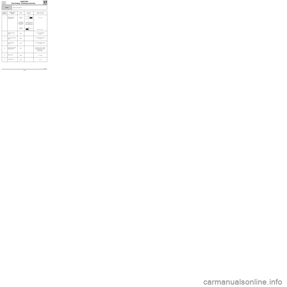
Engine cold, ignition on.NOTES
Order of
operationsFunction to be
checkedAction Bargraph Display and notes
6 Throttle position
potentiometerNo load
# 17
Accelerator
pedal slightly
depressed
Full load
# 17 16 < X < 50
185 < X < 243
7Absolute pressure
sensor# 01 X = Local atmospheric
pressure
8Coolant temperature
sensor# 02 X = Ambient temperature
± 5 °C
9Air temperature
sensor# 03 X = Ambient temperature
± 5 °C
10Idle speed regulation
stepping motor# 12The value read is variable
depending on the coolant
temperature :
7 % ≤ X ≤ 100 %
11Engine speed
# 06 X = 0 rpm
12Canister bleed
# 23 X = 0.7 %
2
2
2
17-65
Page 124 of 363
JSA051.0
INJECTION
Fault finding - Introduction
17
D7F 710
engine -
35 tracks
Driving conditions for programming the adaptive variables:
During the road test, the engine speed must be stabilised for a few moments between:
260 < # 01 < 385 mbars
then 385 < # 01 < 510 mbars
then 510 < # 01 < 635 mbars
then is 635 < # 01 < 760 mbars
then 760 < # 01 < 970 mbars
Do not exceed an engine speed of 4400 rpm
The engine must be warm (coolant temperature > 75 °C).
For this test, start from a fairly low engine speed, in 3rd or 4th gear, and apply progressive acceleration to
stabilise at the pressure required for 10 seconds in each zone.
The test must then be continued by driving normally, in a varied manner for 3 to 6 miles (5 to 10 km).
17-79
Page 133 of 363
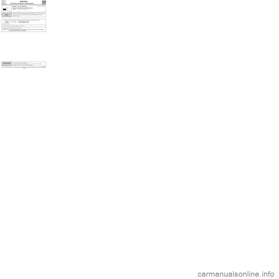
Connect the bornier in place of the computer and check the insulation and continuity of the line:
Computer 15 1 Coolant temperature sensor
Computer 6 2 Coolant temperature sensor
Repair if necessary.
JSA051.0
INJECTION
Fault finding - Interpretation of XR25 bargraphs17
D7F 710
engine -
35 tracks
Erase the computer memory using G0**.
Try to start the engine. Switch the ignition on, then deal with the other faults.
Remember to carry out a status and parameter check.AFTER REPAIR
Bargraph 4 LH side illuminatedFiche n° 27 side 1/2
COOLANT TEMPERATURE SENSOR CIRCUIT
XR25 aid:CO, CC- or CC+line 15 or 6
4
If BG 3LH or BG 5LH or BG 6LH or BG 6RH is also illuminated, check line 15 on the
computer. For certain faults, BG 4LH is only permanently illuminated when the
engine is running.
NOTES
The fault persists! Replace the injection computer.
IMPORTANT: The computer has probably been damaged by an electric shock. The cause of the damage
must be found before fitting a new computer.
Check the resistance of the sensor. Replace it if necessary.
17-88