engine RENAULT KANGOO 1997 KC / 1.G Sheet Metal Work Workshop Manual
[x] Cancel search | Manufacturer: RENAULT, Model Year: 1997, Model line: KANGOO, Model: RENAULT KANGOO 1997 KC / 1.GPages: 255
Page 3 of 255
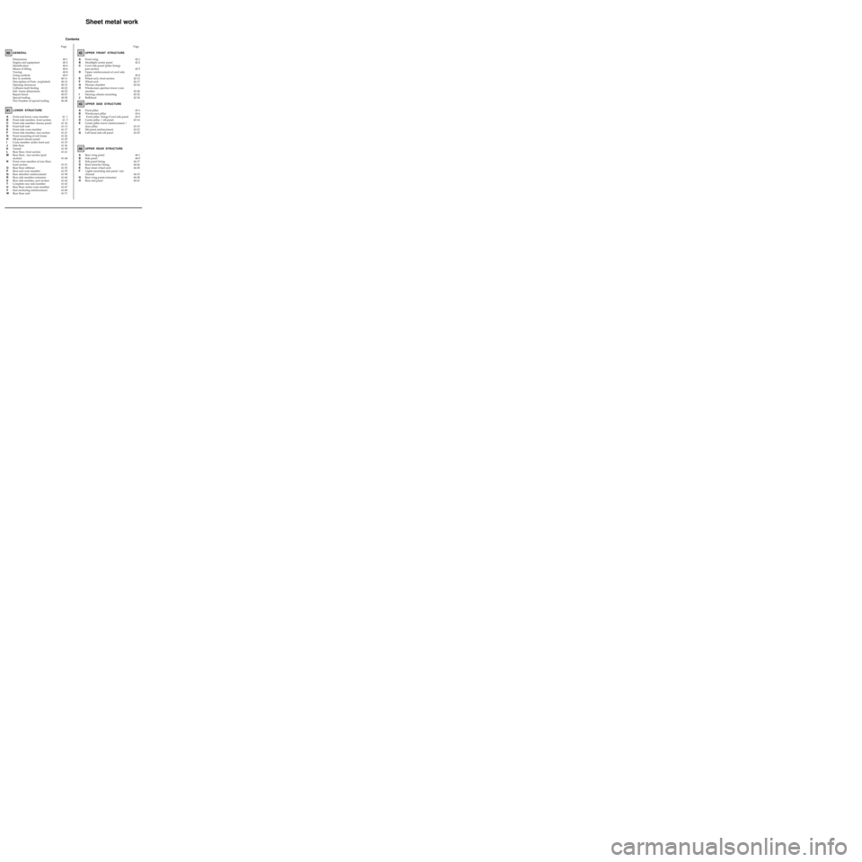
Contents
GENERAL
Dimensions
Engine and equipment
Identification
Means of lifting
Towing
Using symbols
Key to symbols
Description of Parts (exploded)
Opening clearances
Collision fault finding
Sub- frame dimensions
Repair bench
Special tooling
Part Number of special tooling40-1
40-2
40-4
40-6
40-8
40-9
40-11
40-12
40-15
40-22
40-25
40-27
40-38
40-38
LOWER STRUCTURE
41- 1
41- 5
41-10
41-13
41-17
41-21
41-26
41-29
41-33
41-36
41-39
41-41
41-44
41-51
41-53
41-55
41-58
41-60
41-62
41-63
41-67
41-68
41-71UPPER FRONT STRUCTUREPage Page40
41
42
Sheet metal work
UPPER SIDE STRUCTURE43
AFront end lower cross member
BFront side member, front section
CFront side member closure panel
DFront half unit
EFront side cross member
FFront side member, rear section
GFront mounting of sub frame
HSill panel closure panel
ICross member under front seat
JSide floor
KTunnel
LRear floor, front section
MRear floor, rear section (part
section)
NFront cross member of rear floor,
front section
ORear floor stiffener
PRear end cross member
QRear absorber reinforcement
RRear side member extension
SRear side member, part section
TComplete rear side member
URear floor centre cross member
VSeat anchoring reinforcement
WRear floor unit42-1
42-2
42-5
42-8
42-12
42-17
42-24
42-28
42-32
42-34 AFront wing
BHeadlight carrier panel
CCowl side panel (pillar lining)
part section
DUpper reinforcement of cowl side
panel
EWheel arch, front section
FWheel arch
GPlenum chamber
HWindscreen aperture lower cross
member
ISteering column mounting
JBulkhead
43-1
43-6
43-9
43-14
43-19
43-23
43-25 AFront pillar
BWindscreen pillar
C Front pillar lining/Cowl side panel
DCentre pillar / sill panel
ECentre pillar lower reinforcement /
door pillar
FSill panel reinforcement
GLeft hand side sill panel
UPPER REAR STRUCTURE
44
44-1
44-9
44-17
44-26
44-30
44-33
44-38
44-41 ARear wing panel
BSide panel
CSide panel lining
DRoof stretcher lining
ERear inner wheel arch
FLights mounting side panel rain
channel
GRear wing panel extension
HRear end panel
Page 6 of 255
GENERAL
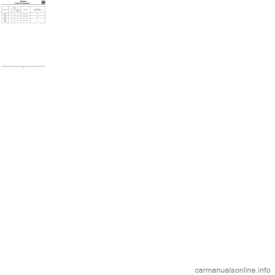
Engine and equipment
40
Vehicle type Engine
TypeCapacity
(cm
3)Clutch type Gearbox type
manual and automatic
FC0A
KC0AD7F 1149 180 CP 3300 JB1
FC0C
KC0CE7J 1390 180 CP 3300 JB3
FC0D
KC0D
FC0E
KC0EF8Q 1870 200 CPOV 3250 JB1
40-2
Page 7 of 255
GENERAL
Engine and equipment
40
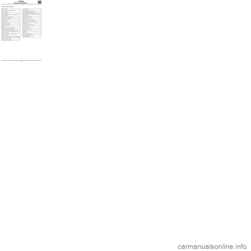
SPECIFIC BODYWORK FEATURES
Driver’s airbag
Passenger’s and driver’s airbag
Height adjustable front head restraint
Height adjustable and tiltable front head restraint
Rear parcel shelf
Luggage compartment net
Electric one touch windows
Heated electric rear view mirrors
Heated screen + timed windscreen wiper
Heated front seats
Front seat driver emergency exit
Rear bench seat 1/1
Rear bench seat 1/3 - 2/3
Cabin rack without stop
Headlining
Boot carpet
Parcel shelf luggage cover
Two front fog lights in bumper
(excluding F8 AC PAS)Pay load 600 kg
Pay load 625 to 710 kg depending on
engine/equipment
Pay load 800 kg
Glazed, sliding side door and rear opening doors
or glazed tailgate
Sliding side door (reflective glass)
Sliding side door (panel)
Rear door, panel
Rear door, glazed
Opening doors, panels
Opening doors, glazed
Tailgate
Opaque roof flap (excluding tailgate)
Glazed roof flap (excluding tailgate)
Fixed side window (meaning glazed side door)
Sliding side window
Fixed rear quarter panel (meaning the glazed
sliding side door )
Heat insulating windscreen (with air conditioning)
2 point rear centre seat belt
3 point rear centre seat belt
40-3
Page 9 of 255
GENERAL
Identification
40
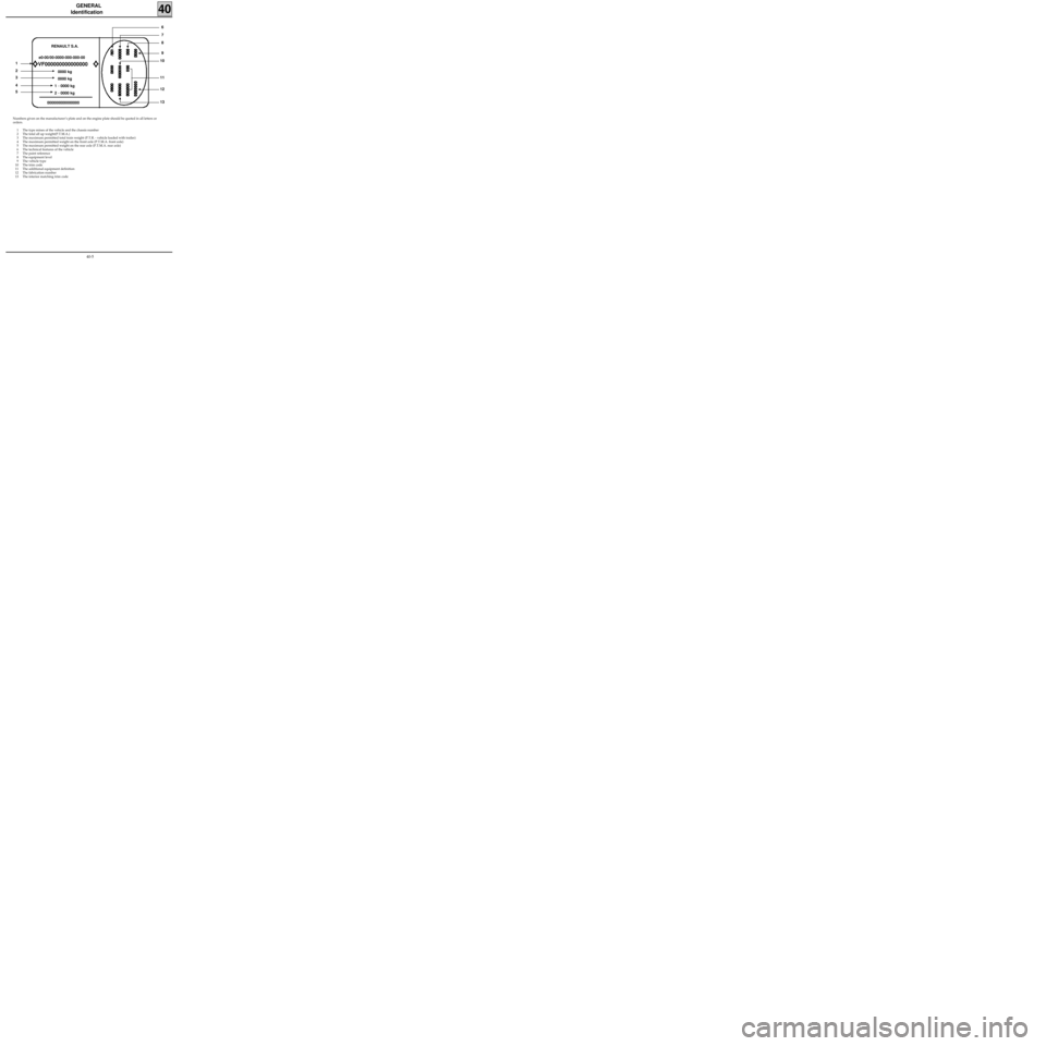
Numbers given on the manufacturer’s plate and on the engine plate should be quoted in all letters or
orders.
1 The type mines of the vehicle and the chassis number
2 The total all up weight(P.T.M.A.)
3 The maximum permitted total train weight (P.T.R. - vehicle loaded with trailer)
4 The maximum permitted weight on the front axle (P.T.M.A. front axle)
5 The maximum permitted weight on the rear axle (P.T.M.A. rear axle)
6 The technical features of the vehicle
7 The paint reference
8 The equipment level
9 The vehicle type
10 The trim code
11 The additional equipment definition
12 The fabrication number
13 The interior matching trim code
e0-00/00-0000-000-000-00
VF000000000000000
0000 kg
0000 kg
1
- 0000 kg
2
- 0000 kg
000000000000000RENAULT S.A.
1
2
3
4
5
8 7
6
9
10
13
12 11
40-5
Page 11 of 255
GENERAL
Means of lifting
40
SAFETY SYMBOL
There are several examples :
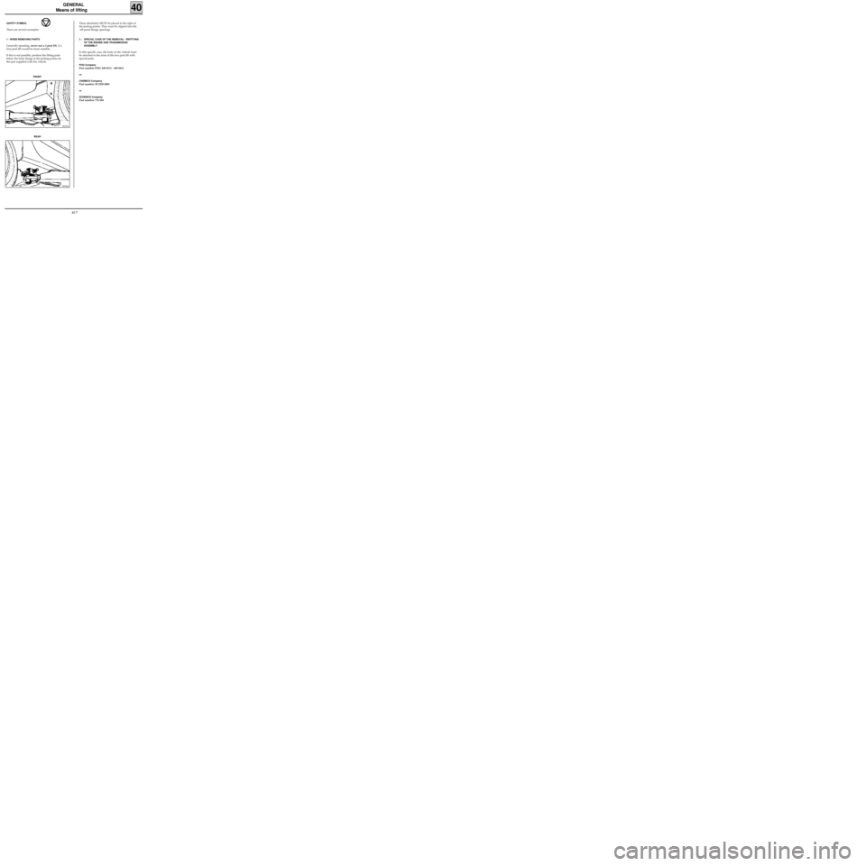
1 - WHEN REMOVING PARTS
Generally speaking, never use a 2 post lift if a
four post lift would be more suitable.
If this is not possible, position the lifting pads
below the body flange at the jacking points for
the jack supplied with the vehicle.
98703S
FRONT
98704S
REAR
These absolutely MUST be placed to the right of
the jacking points. They must be clipped into the
sill panel flange openings.
2 -
SPECIAL CASE OF THE REMOVAL - REFITTING
OF THE ENGINE AND TRANSMISSION
ASSEMBLY
In this specific case, the body of the vehicle must
be attached to the arms of the two post lift with
special pads.
FOG Company
Part number FOG 449 8111 - 449 8411
or
CHEMICO Company
Part number 39 2550 0001
or
SCHENCH Company
Part number 776 684
40-7
Page 29 of 255

GENERAL
Sub-frame dimensions
40
DESCRIPTION X Y ZDIAMETER SLOPE %
A Front sub-frame rear mounting 205 402.5 71 18.5 0
B Rear axle assembly front mounting 1 999.3 657 71.3 20×20 X : 8°20
C Front left sub-frame front mounting - 418 447 13010×10
(squared)0
Front right sub-frame front mounting - 418 465 13010×10
(squared)0
E Rear shock absorber upper mounting 2 333.13 545.75 184 12.5 0
F Front shock absorber upper mounting 18.5 545.50 657 48X : 3°02
Y : 1°
G1 Rear section of front left side member 600 - 375 020×20
(squared)0
Rear section of front right side member 600 351.6 020×20
(squared)0
J Rear point of rear side member 2 918 497.5 151 12.2×16.2 X : 3°
K Front end cross member 575 315 280 14.25X : 4°30
Z : 5°
L Rear end cross member (end panel) 3 121 - 497.5 151 M8 0
P Front engine mounting - 247 483.5 514 M10 0
Rear engine mounting - 113 483.5 514 M10 0
40-25
Page 37 of 255
GENERAL
Repair Bench
40
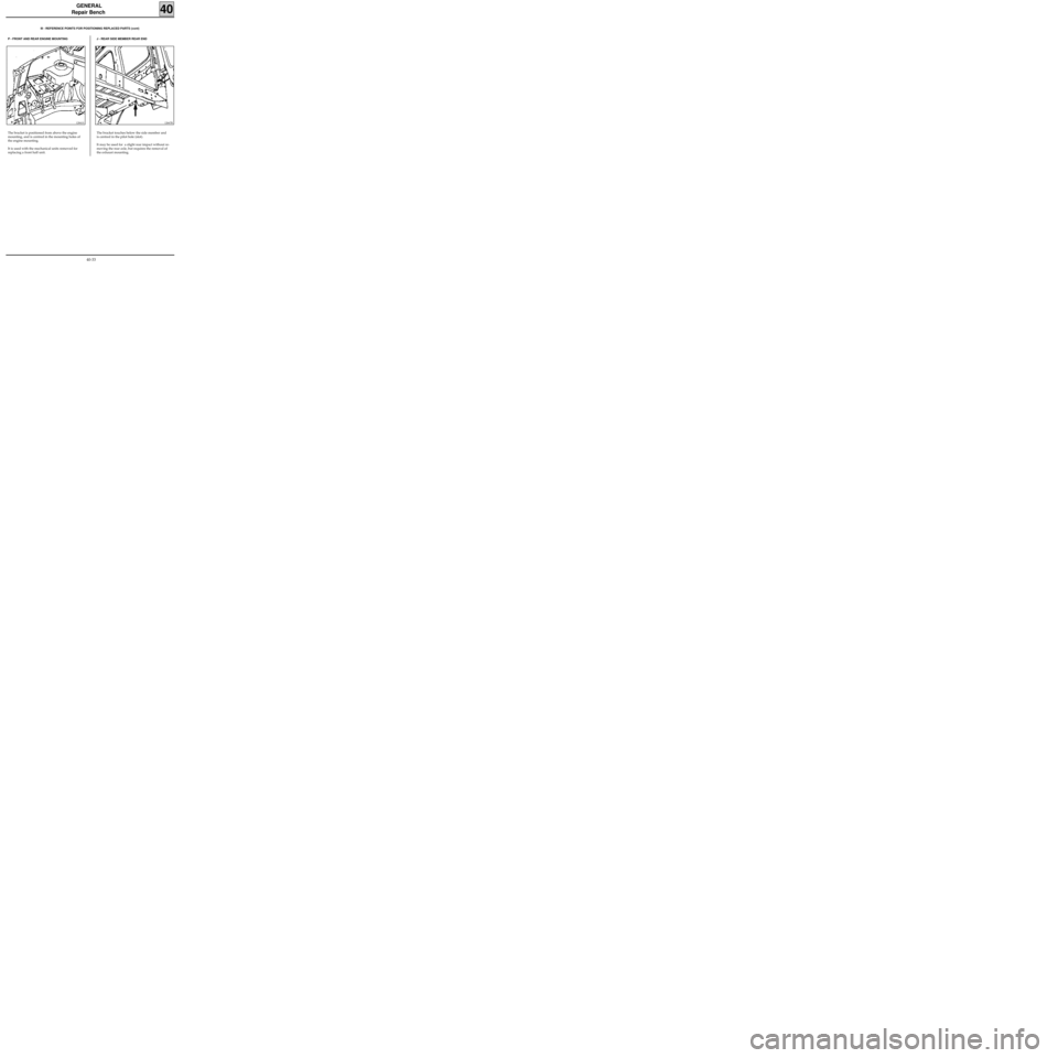
12667R
The bracket touches below the side member and
is centred in the pilot hole (slot).
It may be used for a slight rear impact without re-
moving the rear axle, but requires the removal of
the exhaust mounting.
P - FRONT AND REAR ENGINE MOUNTINGIII - REFERENCE POINTS FOR POSITIONING REPLACED PARTS (cont)
12841S
The bracket is positioned from above the engine
mounting, and is centred in the mounting holes of
the engine mounting.
It is used with the mechanical units removed for
replacing a front half unit.
J - REAR SIDE MEMBER REAR END
40-33
Page 38 of 255
GENERAL
Repair Bench
40
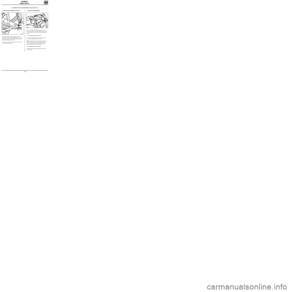
12668R1
The bracket helps with the fitting of the cross
member and rests vertically against the front end
cross member, then it is centred by a centring bolt
at (K).
1 - Front mechanical units removed
It is used for replacing the front end cross mem-
ber, with or without mechanical units.
NOTE : The operation for replacing the front end
cross member can be carried out without the re-
moval of the engine and transmission assembly,
but requires the removal of the radiator.
2 - Front mechanical units in place
The bracket helps with fault finding on the front
cross member.
III - REFERENCE POINTS FOR POSITIONING REPLACED PARTS (cont)
L - REAR END CROSS MEMBER (REAR END)
12667R1
The bracket helps with the fitting of the cross
member and rests vertically against the rear end
cross member, then centres itself in the mounting
hole of the absorber mounting.
It is used for replacing the whole rear end, with or
without mechanical units.
K - FRONT END CROSS MEMBER
40-34
Page 47 of 255
LOWER STRUCTURE
Front side member, front section
41B
PRB4122
INTRODUCTION
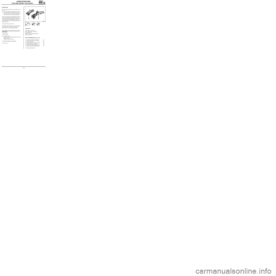
The replacement of this part can be done in two
ways :
A Front side member, complete front section .
B Front side member, partial front section (cut
to be made in front of the front mounting of
the sub-frame), see the following diagram.
In the two cases these are complementary opera-
tions to the replacement of the front end lower
cross member and the headlight carrier panel. As
a result, the joints with these parts will not be
considered here, they will be dealt with in the res-
pective sections.
The repair bench must be used.
The replacement of this part also requires the re-
placement of the side member closure panel
which will have to be ordered separately.
COMPOSITION OF THE PART FROM THE PARTS
DEPARTMENT
1 -Side member
Part assembled with:
- engine mounting height adjuster (only on the
right hand side),
- sub-frame front mounting.
2 - Front side member closure panel
Part on its own.
JOINTS WITH:
Side member closure panel
Front side member, rear section
Front wheel arch
Shock absorber cup height adjuster
Engine mounting *
PARTS CONCERNED (thickness in mm) :
1Front side member, front section 1.5
2Front side member, rear section 2.5
3Front wheel arch 0.8
4Shock absorber cup height adjuster 0.8
5Side member closure panel 1.2
6Engine mounting height adjuster* 1.8
7Engine mounting reinforcement * 1.5
* Only the right hand side.or
41-5
Page 55 of 255
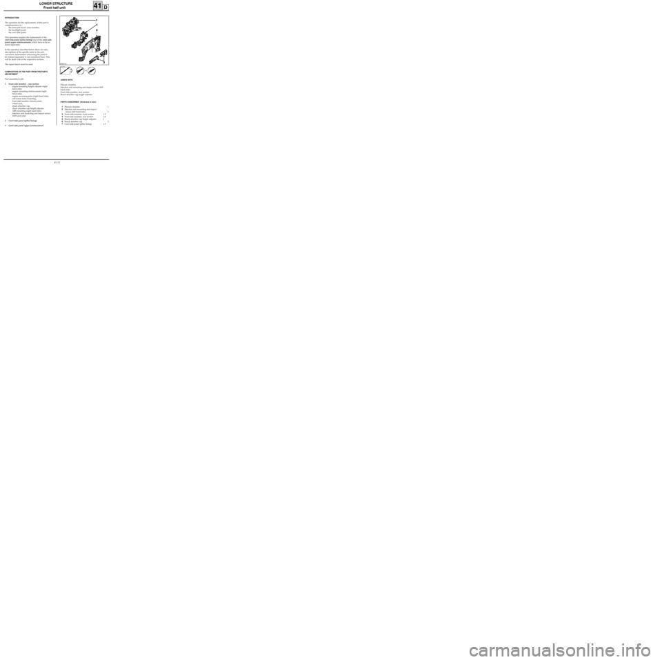
LOWER STRUCTURE
Front half unit
41D
PRB4124
INTRODUCTION
The operation for the replacement of this part is
complementary to :
- the front end lower cross member,
- the headlight panel
- the cowl side panel.
This operation requires the replacement of the
cowl side panel (pillar lining) and of the cowl side
panel upper reinforcements, which have to be or-
dered separately.
In the operation described below there are only
descriptions of the specific joints to the part
concerned, information concerning the parts to
be ordered separately is not considered here. This
will be dealt with in the respective sections.
The repair bench must be used.
COMPOSITION OF THE PART FROM THE PARTS
DEPARTMENT
Part assembled with:
1 Front side member , rear section
- engine mounting height adjuster (right
hand side)
- engine mounting reinforcement (right
hand side),
- engine mounting plate (right hand side),
- sub-frame front mounting,
- front side member closure panel ,
- wheel arch,
- shock absorber cup,
- shock absorber cup height adjuster,
- ABS mounting (right hand side),
- injection unit mounting and impact sensor
(left hand side).
2 Cowl side panel (pillar lining)
3 Cowl side panel upper reinforcementJOINTS WITH:
Plenum chamber
Injection unit mounting and impact sensor (left
hand side)
Front side member, rear section
Shock absorber cup height adjuster
PARTS CONCERNED (thickness in mm) :
1Plenum chamber 1
2Injection unit mounting and impact
sensor (left hand side) 2
3Front side member, front section 1.5
4Front side member, rear section 1.8
5Shock absorber cup height adjuster 1
6Shock absorber cup 2
7Cowl side panel (pillar lining) 1.5or
41-13