RENAULT KANGOO 2013 X61 / 2.G Access Security User Guide
Manufacturer: RENAULT, Model Year: 2013, Model line: KANGOO, Model: RENAULT KANGOO 2013 X61 / 2.GPages: 48, PDF Size: 0.31 MB
Page 11 of 48
82D-11V1 MR-376-X76-82D000$040.mif
ACCESS - SECURITY
Fault finding – Function82D
UCH
Vdiag No.: 0F
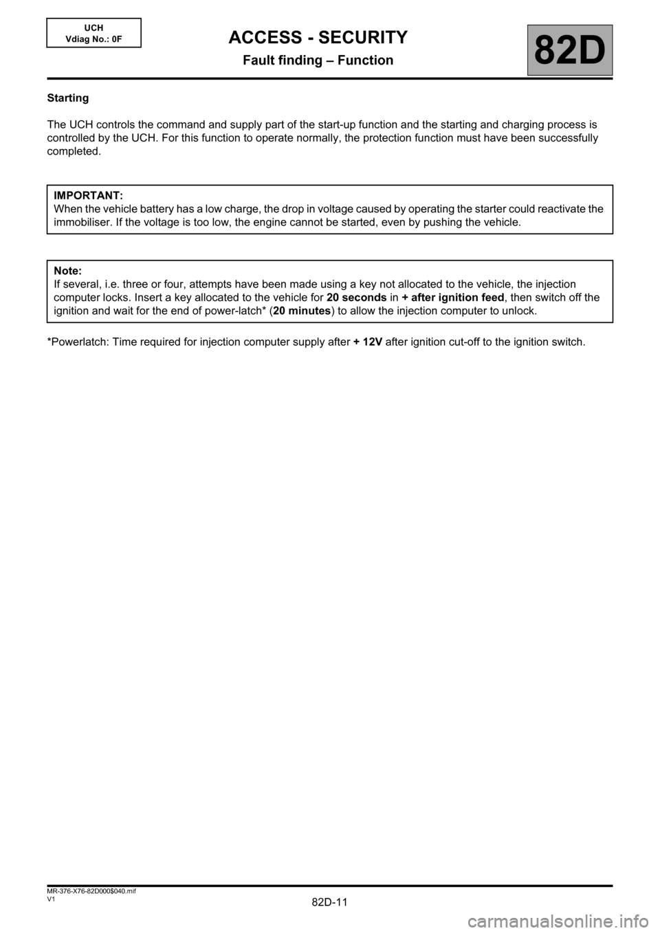
Starting
The UCH controls the command and supply part of the start-up function and the starting and charging process is
controlled by the UCH. For this function to operate normally, the protection function must have been successfully
completed.
*Powerlatch: Time required for injection computer supply after + 12V after ignition cut-off to the ignition switch. IMPORTANT:
When the vehicle battery has a low charge, the drop in voltage caused by operating the starter could reactivate the
immobiliser. If the voltage is too low, the engine cannot be started, even by pushing the vehicle.
Note:
If several, i.e. three or four, attempts have been made using a key not allocated to the vehicle, the injection
computer locks. Insert a key allocated to the vehicle for 20 seconds in + after ignition feed, then switch off the
ignition and wait for the end of power-latch* (20 minutes) to allow the injection computer to unlock.
Page 12 of 48
82D-12V1 MR-376-X76-82D000$050.mif
82D
UCH
Vdiag No.: 0F
CONFIGURATION
New parts are not coded. Once fitted on the vehicle, they must be programmed with a code to become operational.
To perform this procedure, it is essential that some parts on the vehicle are already correctly coded (with the vehicle
code).
Refer to the allocation table.
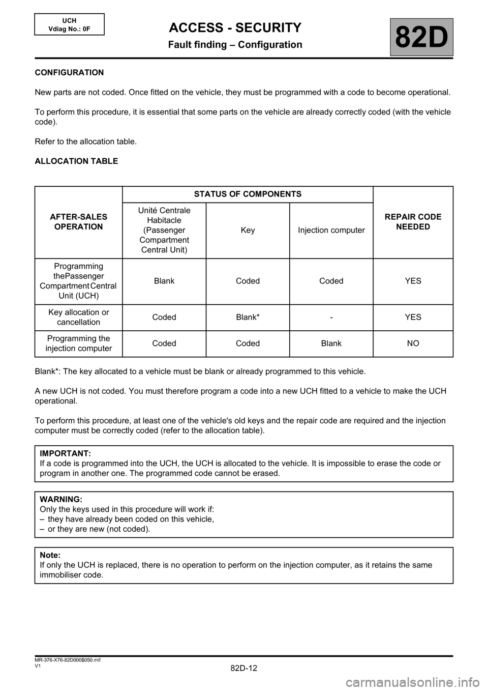
ALLOCATION TABLE
Blank*: The key allocated to a vehicle must be blank or already programmed to this vehicle.
A new UCH is not coded. You must therefore program a code into a new UCH fitted to a vehicle to make the UCH
operational.
To perform this procedure, at least one of the vehicle's old keys and the repair code are required and the injection
computer must be correctly coded (refer to the allocation table).AFTER-SALES
OPERATIONSTATUS OF COMPONENTS
REPAIR CODE
NEEDED Unité Centrale
Habitacle
(Passenger
Compartment
Central Unit)Key Injection computer
Programming
thePassenger
Compartment Central
Unit (UCH)Blank Coded Coded YES
Key allocation or
cancellationCoded Blank* - YES
Programming the
injection computerCoded Coded Blank NO
IMPORTANT:
If a code is programmed into the UCH, the UCH is allocated to the vehicle. It is impossible to erase the code or
program in another one. The programmed code cannot be erased.
WARNING:
Only the keys used in this procedure will work if:
– they have already been coded on this vehicle,
– or they are new (not coded).
Note:
If only the UCH is replaced, there is no operation to perform on the injection computer, as it retains the same
immobiliser code.
ACCESS - SECURITY
Fault finding – Configuration
Page 13 of 48
82D-13V1 MR-376-X76-82D000$050.mif
ACCESS - SECURITY
Fault finding – Configuration82D
UCH
Vdiag No.: 0F
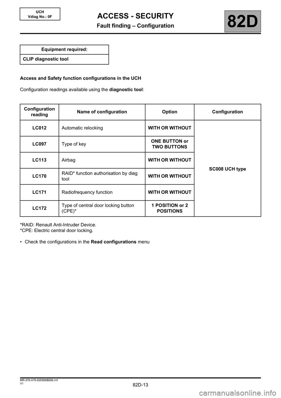
Access and Safety function configurations in the UCH
Configuration readings available using the diagnostic tool:
*RAID: Renault Anti-Intruder Device.
*CPE: Electric central door locking.
• Check the configurations in the Read configurations menu Equipment required:
CLIP diagnostic tool
Configuration
readingName of configuration Option Configuration
LC012Automatic relockingWITH OR WITHOUT
SC008 UCH type LC097Type of keyONE BUTTON or
TWO BUTTONS
LC113AirbagWITH OR WITHOUT
LC170RAID* function authorisation by diag
toolWITH OR WITHOUT
LC171Radiofrequency functionWITH OR WITHOUT
LC172Type of central door locking button
(CPE)*1 POSITION or 2
POSITIONS
Page 14 of 48
82D-14V1 MR-376-X76-82D000$060.mif
82D
UCH
Vdiag No.: 0F
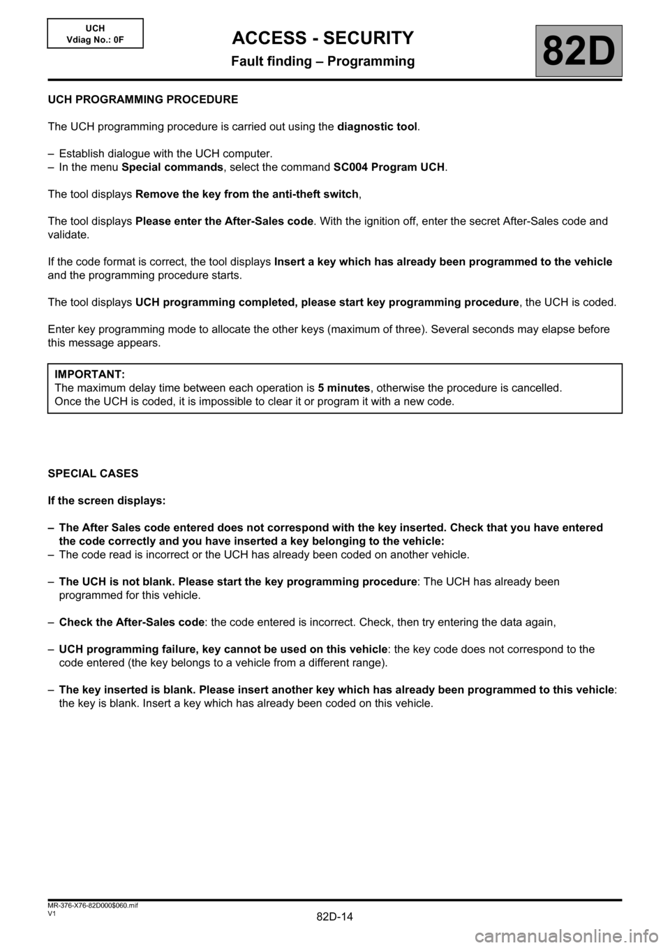
UCH PROGRAMMING PROCEDURE
The UCH programming procedure is carried out using the diagnostic tool.
– Establish dialogue with the UCH computer.
– In the menu Special commands, select the command SC004 Program UCH.
The tool displays Remove the key from the anti-theft switch,
The tool displays Please enter the After-Sales code. With the ignition off, enter the secret After-Sales code and
validate.
If the code format is correct, the tool displays Insert a key which has already been programmed to the vehicle
and the programming procedure starts.
The tool displays UCH programming completed, please start key programming procedure, the UCH is coded.
Enter key programming mode to allocate the other keys (maximum of three). Several seconds may elapse before
this message appears.
SPECIAL CASES
If the screen displays:
– The After Sales code entered does not correspond with the key inserted. Check that you have entered
the code correctly and you have inserted a key belonging to the vehicle:
– The code read is incorrect or the UCH has already been coded on another vehicle.
–The UCH is not blank. Please start the key programming procedure: The UCH has already been
programmed for this vehicle.
–Check the After-Sales code: the code entered is incorrect. Check, then try entering the data again,
–UCH programming failure, key cannot be used on this vehicle: the key code does not correspond to the
code entered (the key belongs to a vehicle from a different range).
–The key inserted is blank. Please insert another key which has already been programmed to this vehicle:
the key is blank. Insert a key which has already been coded on this vehicle. IMPORTANT:
The maximum delay time between each operation is 5 minutes, otherwise the procedure is cancelled.
Once the UCH is coded, it is impossible to clear it or program it with a new code.
ACCESS - SECURITY
Fault finding – Programming
Page 15 of 48
82D-15V1 MR-376-X76-82D000$060.mif
ACCESS - SECURITY
Fault finding – Programming82D
UCH
Vdiag No.: 0F
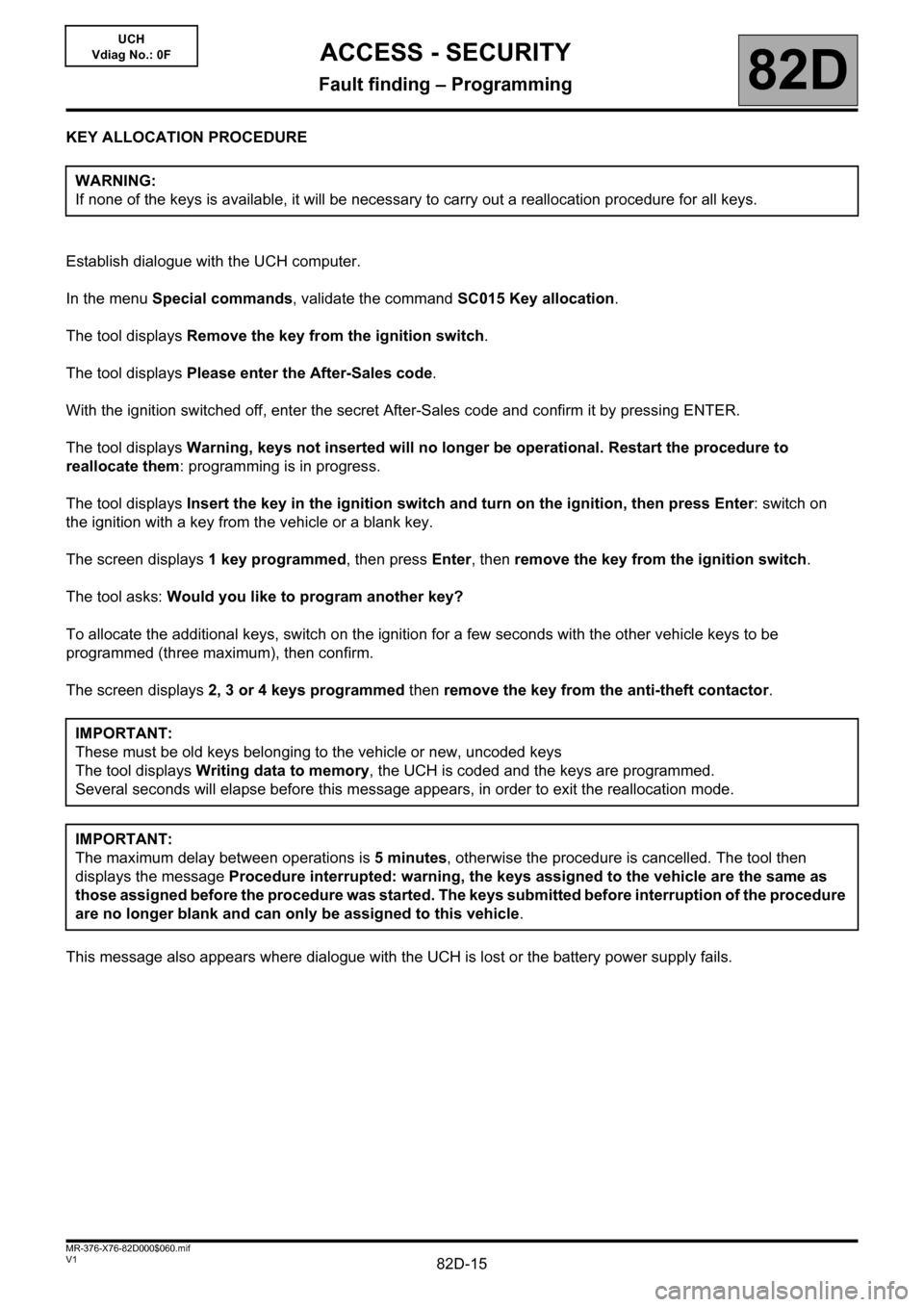
KEY ALLOCATION PROCEDURE
Establish dialogue with the UCH computer.
In the menu Special commands, validate the command SC015 Key allocation.
The tool displays Remove the key from the ignition switch.
The tool displays Please enter the After-Sales code.
With the ignition switched off, enter the secret After-Sales code and confirm it by pressing ENTER.
The tool displays Warning, keys not inserted will no longer be operational. Restart the procedure to
reallocate them: programming is in progress.
The tool displays Insert the key in the ignition switch and turn on the ignition, then press Enter: switch on
the ignition with a key from the vehicle or a blank key.
The screen displays 1 key programmed, then press Enter, then remove the key from the ignition switch.
The tool asks: Would you like to program another key?
To allocate the additional keys, switch on the ignition for a few seconds with the other vehicle keys to be
programmed (three maximum), then confirm.
The screen displays 2, 3 or 4 keys programmed then remove the key from the anti-theft contactor.
This message also appears where dialogue with the UCH is lost or the battery power supply fails.WARNING:
If none of the keys is available, it will be necessary to carry out a reallocation procedure for all keys.
IMPORTANT:
These must be old keys belonging to the vehicle or new, uncoded keys
The tool displays Writing data to memory, the UCH is coded and the keys are programmed.
Several seconds will elapse before this message appears, in order to exit the reallocation mode.
IMPORTANT:
The maximum delay between operations is 5 minutes, otherwise the procedure is cancelled. The tool then
displays the message Procedure interrupted: warning, the keys assigned to the vehicle are the same as
those assigned before the procedure was started. The keys submitted before interruption of the procedure
are no longer blank and can only be assigned to this vehicle.
Page 16 of 48
82D-16V1 MR-376-X76-82D000$060.mif
ACCESS - SECURITY
Fault finding – Programming82D
UCH
Vdiag No.: 0F
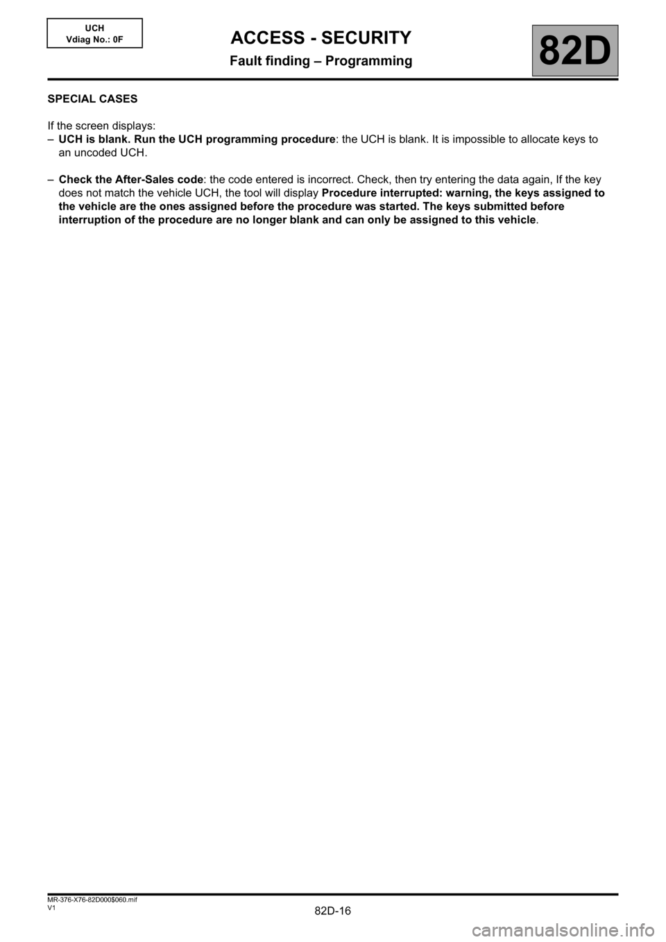
SPECIAL CASES
If the screen displays:
–UCH is blank. Run the UCH programming procedure: the UCH is blank. It is impossible to allocate keys to
an uncoded UCH.
–Check the After-Sales code: the code entered is incorrect. Check, then try entering the data again, If the key
does not match the vehicle UCH, the tool will display Procedure interrupted: warning, the keys assigned to
the vehicle are the ones assigned before the procedure was started. The keys submitted before
interruption of the procedure are no longer blank and can only be assigned to this vehicle.
Page 17 of 48
82D-17V1 MR-376-X76-82D000$070.mif
82D
UCH
Vdiag No.: 0F
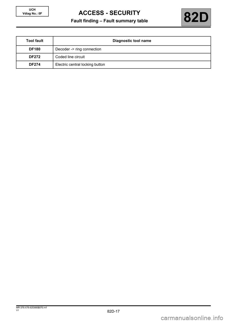
Tool fault Diagnostic tool name
DF180Decoder -> ring connection
DF272Coded line circuit
DF274Electric central locking button
ACCESS - SECURITY
Fault finding – Fault summary table
Page 18 of 48
82D-18
AFTER REPAIRFollow the instructions.
Deal with any other faults.
Clear the stored faults.
V1 MR-376-X76-82D000$080.mif
82D
UCH
Vdiag No.: 0F
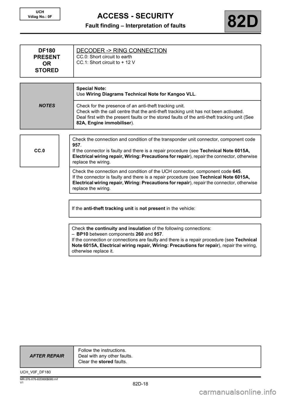
DF180
PRESENT
OR
STOREDDECODER -> RING CONNECTION
CC.0: Short circuit to earth
CC.1: Short circuit to + 12 V
NOTESSpecial Note:
Use Wiring Diagrams Technical Note for Kangoo VLL.
Check for the presence of an anti-theft tracking unit.
Check with the call centre that the anti-theft tracking unit has not been activated.
Deal first with the present faults or the stored faults of the anti-theft tracking unit (See
82A, Engine immobiliser).
CC.0Check the connection and condition of the transponder unit connector, component code
957.
If the connector is faulty and there is a repair procedure (see Technical Note 6015A,
Electrical wiring repair, Wiring: Precautions for repair), repair the connector, otherwise
replace the wiring.
Check the connection and condition of the UCH connector, component code 645.
If the connector is faulty and there is a repair procedure (see Technical Note 6015A,
Electrical wiring repair, Wiring: Precautions for repair), repair the connector, otherwise
replace the wiring.
If the anti-theft tracking unit is not present in the vehicle:
Check the continuity and insulation of the following connections:
–BP10 between components 260 and 957.
If the connection or connections are faulty and there is a repair procedure (see Technical
Note 6015A, Electrical wiring repair, Wiring: Precautions for repair), repair the wiring,
otherwise replace it.
UCH_V0F_DF180
ACCESS - SECURITY
Fault finding – Interpretation of faults
Page 19 of 48
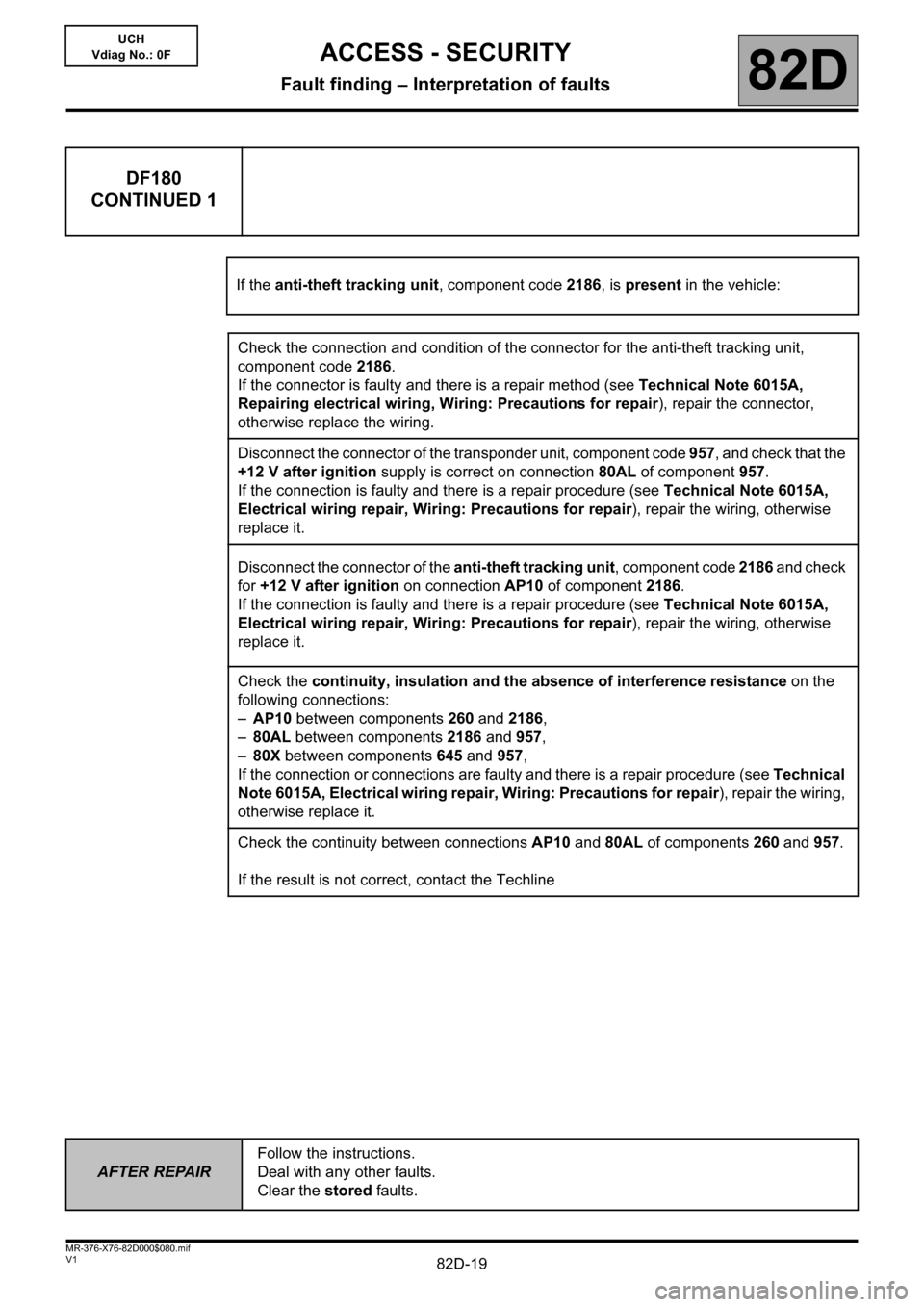
82D-19
AFTER REPAIRFollow the instructions.
Deal with any other faults.
Clear the stored faults.
V1 MR-376-X76-82D000$080.mif
ACCESS - SECURITY
Fault finding – Interpretation of faults82D
UCH
Vdiag No.: 0F
DF180
CONTINUED 1
If the anti-theft tracking unit, component code 2186, is present in the vehicle:
Check the connection and condition of the connector for the anti-theft tracking unit,
component code2186.
If the connector is faulty and there is a repair method (see Technical Note 6015A,
Repairing electrical wiring, Wiring: Precautions for repair), repair the connector,
otherwise replace the wiring.
Disconnect the connector of the transponder unit, component code 957, and check that the
+12 V after ignition supply is correct on connection 80AL of component 957.
If the connection is faulty and there is a repair procedure (see Technical Note 6015A,
Electrical wiring repair, Wiring: Precautions for repair), repair the wiring, otherwise
replace it.
Disconnect the connector of the anti-theft tracking unit, component code 2186 and check
for +12 V after ignition on connection AP10 of component 2186.
If the connection is faulty and there is a repair procedure (see Technical Note 6015A,
Electrical wiring repair, Wiring: Precautions for repair), repair the wiring, otherwise
replace it.
Check the continuity, insulation and the absence of interference resistance on the
following connections:
–AP10 between components 260 and 2186,
–80AL between components 2186 and 957,
–80X between components 645 and 957,
If the connection or connections are faulty and there is a repair procedure (see Technical
Note 6015A, Electrical wiring repair, Wiring: Precautions for repair), repair the wiring,
otherwise replace it.
Check the continuity between connections AP10 and 80AL of components 260 and 957.
If the result is not correct, contact the Techline
Page 20 of 48

82D-20
AFTER REPAIRFollow the instructions.
Deal with any other faults.
Clear the stored faults.
V1 MR-376-X76-82D000$080.mif
ACCESS - SECURITY
Fault finding – Interpretation of faults82D
UCH
Vdiag No.: 0F
DF180
CONTINUED 2
CC.1Check the connection and condition of the transponder unit connector, component code
957.
If the connector is faulty and there is a repair method (see Technical Note 6015A,
Repairing electrical wiring, Wiring: Precautions for repair), repair the connector,
otherwise replace the wiring.
Check the connection and condition of the UCH connector, component code 645.
If the connector is faulty and there is a repair method (see Technical Note 6015A,
Repairing electrical wiring, Wiring: Precautions for repair), repair the connector,
otherwise replace the wiring.
Check the continuity and insulation to +12 V on the following connections:
•NA of component 957
•80X between components 645 and 957.
If the connection or connections are faulty and there is a repair procedure (see Technical
Note 6015A, Electrical wiring repair, Wiring: Precautions for repair), repair the wiring,
otherwise replace it.
If the fault is still present, contact the Techline.