RENAULT KANGOO 2013 X61 / 2.G Access Security Owner's Guide
Manufacturer: RENAULT, Model Year: 2013, Model line: KANGOO, Model: RENAULT KANGOO 2013 X61 / 2.GPages: 48, PDF Size: 0.31 MB
Page 31 of 48
82D-31
AFTER REPAIRCarry out another fault finding check on the system.
Deal with any other faults.
Clear the stored faults.
V1 MR-376-X76-82D000$150.mif
82D
UCH
Vdiag No.: 0F
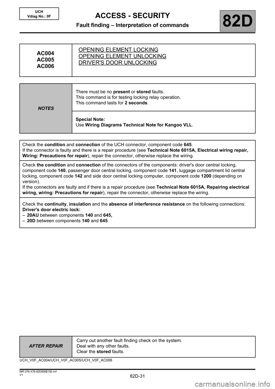
AC004
AC005
AC006OPENING ELEMENT LOCKINGOPENING ELEMENT UNLOCKING
DRIVER'S DOOR UNLOCKING
NOTESThere must be no present or stored faults.
This command is for testing locking relay operation.
This command lasts for 2 seconds.
Special Note:
Use Wiring Diagrams Technical Note for Kangoo VLL.
Check the condition and connection of the UCH connector, component code 645.
If the connector is faulty and there is a repair procedure (see Technical Note 6015A, Electrical wiring repair,
Wiring: Precautions for repair), repair the connector, otherwise replace the wiring.
Check the condition and connection of the connectors of the components: driver's door central locking,
component code 140, passenger door central locking, component code 141, luggage compartment lid central
locking, component code 142 and side door central locking computer, component code 1200 (depending on
version).
If the connectors are faulty and if there is a repair procedure (see Technical Note 6015A, Repairing electrical
wiring, wiring: Precautions for repair), repair the connector, otherwise replace the wiring.
Check the continuity, insulation and the absence of interference resistance on the following connections:
Driver's door electric lock:
–20AU between components 140 and 645,
–20D between components 140 and 645.
UCH_V0F_AC004/UCH_V0F_AC005/UCH_V0F_AC006
ACCESS - SECURITY
Fault finding – Interpretation of commands
Page 32 of 48
82D-32
AFTER REPAIRCarry out another fault finding check on the system.
Deal with any other faults.
Clear the stored faults.
V1 MR-376-X76-82D000$150.mif
ACCESS - SECURITY
Fault finding – Interpretation of commands82D
UCH
Vdiag No.: 0F
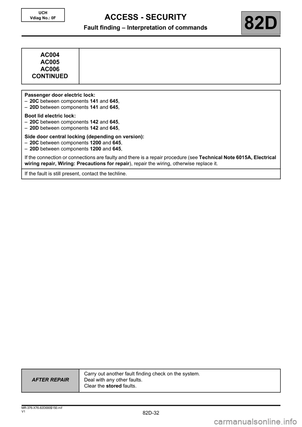
AC004
AC005
AC006
CONTINUED
Passenger door electric lock:
–20C between components 141 and 645,
–20D between components 141 and 645,
Boot lid electric lock:
–20C between components 142 and 645,
–20D between components 142 and 645,
Side door central locking (depending on version):
–20C between components 1200 and 645,
–20D between components 1200 and 645,
If the connection or connections are faulty and there is a repair procedure (see Technical Note 6015A, Electrical
wiring repair, Wiring: Precautions for repair), repair the wiring, otherwise replace it.
If the fault is still present, contact the techline.
Page 33 of 48
82D-33
AFTER REPAIRCarry out another fault finding check on the system.
Deal with any other faults.
Clear the stored faults.
V1 MR-376-X76-82D000$150.mif
ACCESS - SECURITY
Fault finding – Interpretation of commands82D
UCH
Vdiag No.: 0F
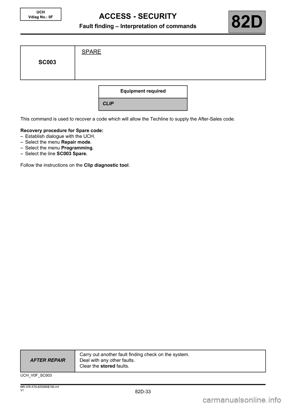
This command is used to recover a code which will allow the Techline to supply the After-Sales code.
Recovery procedure for Spare code:
– Establish dialogue with the UCH.
– Select the menu Repair mode.
– Select the menu Programming.
– Select the line SC003 Spare.
Follow the instructions on the Clip diagnostic tool.
SC003SPARE
Equipment required
CLIP
UCH_V0F_SC003
Page 34 of 48
82D-34
AFTER REPAIRCarry out another fault finding check on the system.
Deal with any other faults.
Clear the stored faults.
V1 MR-376-X76-82D000$150.mif
ACCESS - SECURITY
Fault finding – Interpretation of commands82D
UCH
Vdiag No.: 0F
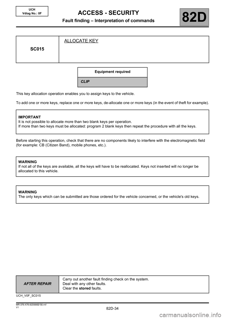
This key allocation operation enables you to assign keys to the vehicle.
To add one or more keys, replace one or more keys, de-allocate one or more keys (in the event of theft for example).
Before starting this operation, check that there are no components likely to interfere with the electromagnetic field
(for example: CB (Citizen Band), mobile phones, etc.).
SC015ALLOCATE KEY
Equipment required
CLIP
IMPORTANT
It is not possible to allocate more than two blank keys per operation.
If more than two keys must be allocated: program 2 blank keys then repeat the procedure with all the keys.
WARNING
If not all of the keys are available, all the keys will have to be reallocated. Keys not inserted will no longer be
allocated to this vehicle.
WARNING
The only keys which can be submitted are those ordered for the vehicle concerned, or the vehicle's old keys.
UCH_V0F_SC015
Page 35 of 48
82D-35
AFTER REPAIRCarry out another fault finding check on the system.
Deal with any other faults.
Clear the stored faults.
V1 MR-376-X76-82D000$150.mif
ACCESS - SECURITY
Fault finding – Interpretation of commands82D
UCH
Vdiag No.: 0F
The UCH must not be blank in order to be able to program keys.
With this system it is not possible to replace some components, such as the UCH and the key as these parts are
sold blank and uncoded.
SC015
CONTINUED 1
IMPORTANT
Do not interrupt the procedure when it is in progress.
If it is interrupted, restart the procedure in "not connected mode"; a new programming key will be displayed.
IMPORTANT
When the programming operation is complete, only remove the key once the Remove key message is displayed
on the screen. Otherwise the programming operation fails and the key will be unusable.
WARNING
When the tool issues the programming key, the user has a limited time in which to enter the immobiliser code.
If the time has elapsed, the CLIP tool displays the message: Time elapsed. Restart the procedure.
Page 36 of 48
82D-36
AFTER REPAIRCarry out another fault finding check on the system.
Deal with any other faults.
Clear the stored faults.
V1 MR-376-X76-82D000$150.mif
ACCESS - SECURITY
Fault finding – Interpretation of commands82D
UCH
Vdiag No.: 0F
Key allocation procedure
– Establish dialogue with the UCH.
– Select the Repair mode menu.
– Select the Programming menu.
– Select line SC015 Allocate key.
The key allocation procedure takes place in two stages:
1. Key insertion stage.
2. Key allocation stage.
1- Key insertion stage
Clip requires that the keys to be allocated are inserted.
Insert ALL the keys to be allocated (old and new blank keys). Any keys not inserted at this stage will be rejected at
the Key allocation stage and the operation will have to be restarted from the beginning.
Once all the keys are inserted, the Clip diagnostic tool displays the programming key in "not connected" mode.
To obtain the immobiliser code, (see Technical Note 5037A, Code delivery procedure).
2- Key allocation stage:
Continue the procedure following the instructions on the Clip diagnostic tool.
Once the keys have been allocated, make sure that all the keys can lock and start the vehicle.
SC015
CONTINUED 2
IMPORTANT
In "not connected" mode, the programming key can only be used for a limited amount of time, as indicated by the
CLIP diagnostic tool. After this time, the programming key and associated immobiliser code are no longer valid.
The operation must be restarted from the beginning.
Page 37 of 48
82D-37V1 MR-376-X76-82D000$160.mif
82D
UCH
Vdiag No.: 0F
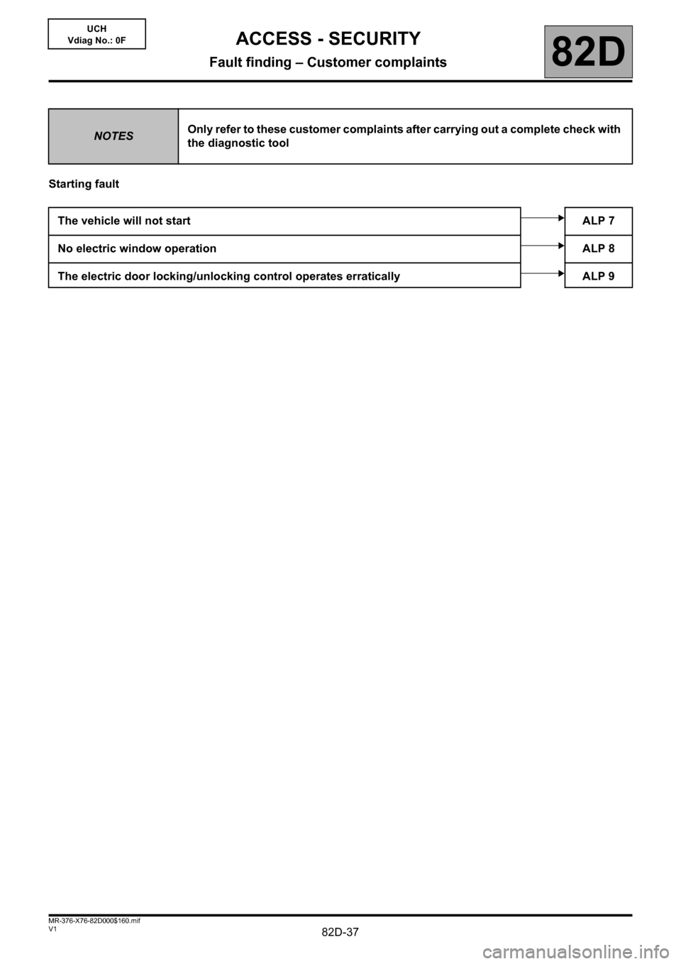
Starting fault
NOTESOnly refer to these customer complaints after carrying out a complete check with
the diagnostic tool
The vehicle will not startALP 7
No electric window operationALP 8
The electric door locking/unlocking control operates erratically ALP 9
ACCESS - SECURITY
Fault finding – Customer complaints
Page 38 of 48
82D-38
AFTER REPAIRCarry out a complete check with the diagnostic tool.
V1 MR-376-X76-82D000$170.mif
82D
UCH
Vdiag No.: 0F
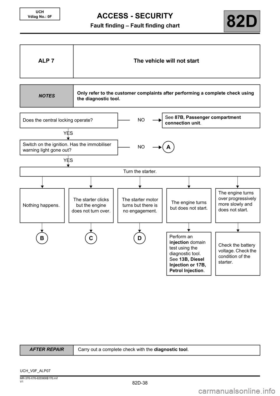
ALP 7 The vehicle will not start
NOTESOnly refer to the customer complaints after performing a complete check using
the diagnostic tool.
Does the central locking operate?See 87B, Passenger compartment
connection unit.
Switch on the ignition. Has the immobiliser
warning light gone out?
Turn the starter.
Nothing happens.The starter clicks
but the engine
does not turn over.The starter motor
turns but there is
no engagement.The engine turns
but does not start.The engine turns
over progressively
more slowly and
does not start.
Perform an
injection domain
test using the
diagnostic tool.
See 13B, Diesel
Injection or 17B,
Petrol Injection.Check the battery
voltage. Check the
condition of the
starter.
NO
YES
NOA
YES
BCD
UCH_V0F_ALP07
ACCESS - SECURITY
Fault finding – Fault finding chart
Page 39 of 48
82D-39
AFTER REPAIRCarry out a complete check with the diagnostic tool.
V1 MR-376-X76-82D000$170.mif
ACCESS - SECURITY
Fault finding – Fault finding chart82D
UCH
Vdiag No.: 0F
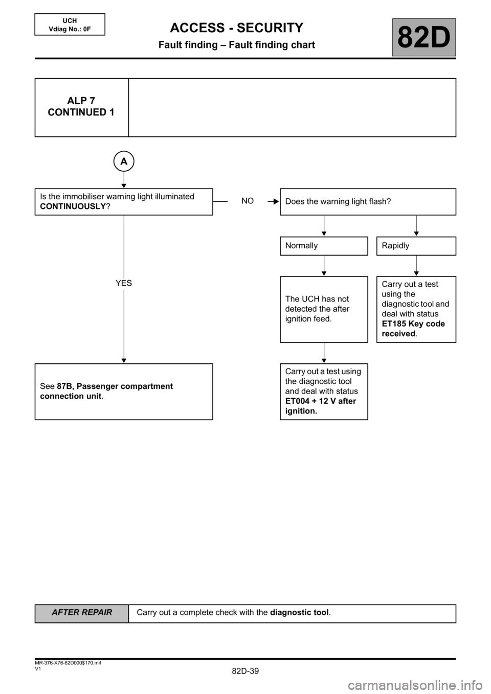
ALP 7
CONTINUED 1
Is the immobiliser warning light illuminated
CONTINUOUSLY?Does the warning light flash?
Normally Rapidly
The UCH has not
detected the after
ignition feed.Carry out a test
using the
diagnostic tool and
deal with status
ET185 Key code
received.
See 87B, Passenger compartment
connection unit.Carry out a test using
the diagnostic tool
and deal with status
ET004 + 12 V after
ignition.
A
NO
YES
Page 40 of 48
82D-40
AFTER REPAIRCarry out a complete check with the diagnostic tool.
V1 MR-376-X76-82D000$170.mif
ACCESS - SECURITY
Fault finding – Fault finding chart82D
UCH
Vdiag No.: 0F
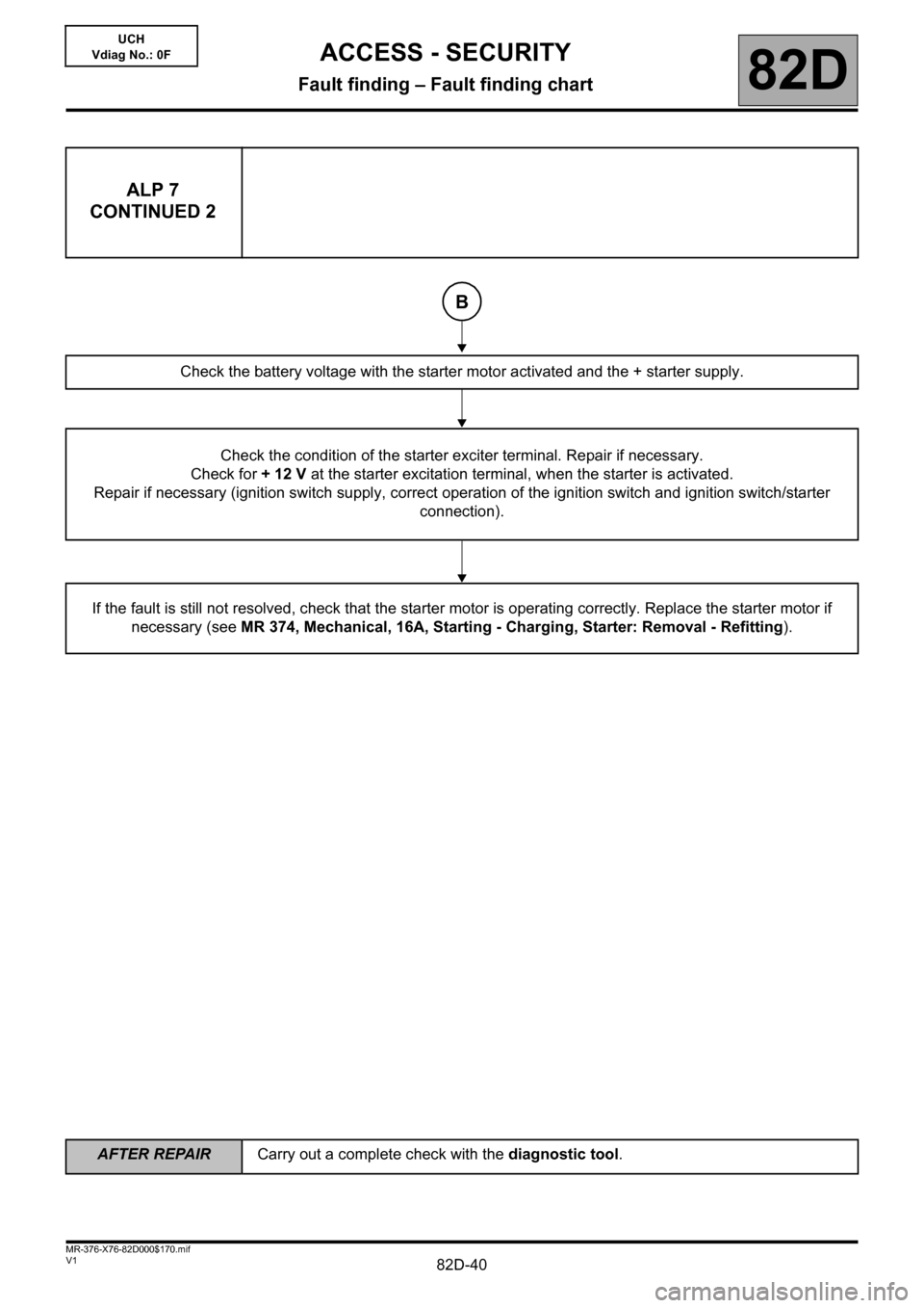
ALP 7
CONTINUED 2
Check the battery voltage with the starter motor activated and the + starter supply.
Check the condition of the starter exciter terminal. Repair if necessary.
Check for +12V at the starter excitation terminal, when the starter is activated.
Repair if necessary (ignition switch supply, correct operation of the ignition switch and ignition switch/starter
connection).
If the fault is still not resolved, check that the starter motor is operating correctly. Replace the starter motor if
necessary (see MR 374, Mechanical, 16A, Starting - Charging, Starter: Removal - Refitting).
B