ABS RENAULT SCENIC 2008 J84 / 2.G Passenger Comparment Connection Unit Service Manual
[x] Cancel search | Manufacturer: RENAULT, Model Year: 2008, Model line: SCENIC, Model: RENAULT SCENIC 2008 J84 / 2.GPages: 391
Page 155 of 391
PASSENGER COMPARTMENT CONNECTION UNIT
Fault finding - Interpretation of statuses
87B
87B -155
PASSENGER COMPARTMENT CONNECTION UNIT
Fault finding - Interpretation of statuses
87B
87B -155V9 MR-372-J84-87B000$473.mif
UCH
Vdiag No.: 44, 48,
4C, 4D, 4F, 50
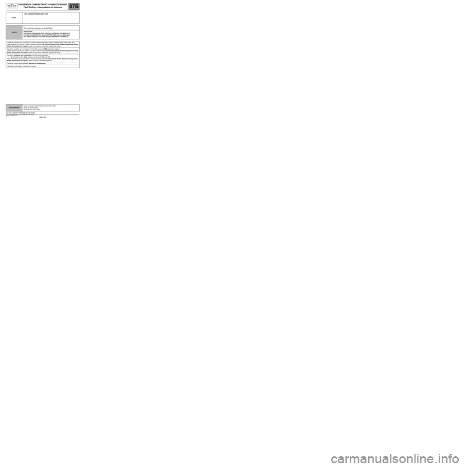
ET029
AIR CONDITIONING BUTTON
NOTESThere must be no present or stored faults.
Special note:
Information interpretable if the vehicle is configured with Manual Air
Conditioning (SC008 UCH type and CF019 Type of air conditioning).
Use Wiring Diagrams Technical Note for MEGANE II or SCENIC II.
Check the condition and connection of the air conditioning control panel connector (bent, broken tabs, etc.).
If the connector is faulty and if there is a repair method (see Technical Note 6015A, Repairing electrical wiring,
Wiring: Precautions for repair), repair the connector; otherwise, replace the wiring.
Check the condition and connection of the UCH connector PE2 (tabs bent, broken).
If the connector is faulty and if there is a repair method (see Technical Note 6015A, Repairing electrical wiring,
Wiring: Precautions for repair), repair the connector; otherwise, replace the wiring.
Check the insulation and continuity of the following connection:
●Connection code 38AL between components 645 and 319.
If the connection is faulty and there is a repair procedure (see Technical Note 6015A, Electrical wiring repair,
Wiring: Precautions for repair), repair the wiring, otherwise replace it.
Check the control panel (see 62C, Manual air conditioning).
If the fault is still present, contact the Techline.
AFTER REPAIRCarry out another fault finding check on the system.
Clear the stored faults.
Deal with any other faults.
UCH_V44_ET029/UCH_V48_ET029/ UCH_V4C_ET029/
UCH_V4D_ET029 /UCH_V4F_ET029/UCH_V50_ET029
Page 158 of 391
PASSENGER COMPARTMENT CONNECTION UNIT
Fault finding - Interpretation of statuses
87B
87B -158
PASSENGER COMPARTMENT CONNECTION UNIT
Fault finding - Interpretation of statuses
87B
87B -158V9 MR-372-J84-87B000$473.mif
UCH
Vdiag No.: 44, 48,
4C, 4D, 4F, 50
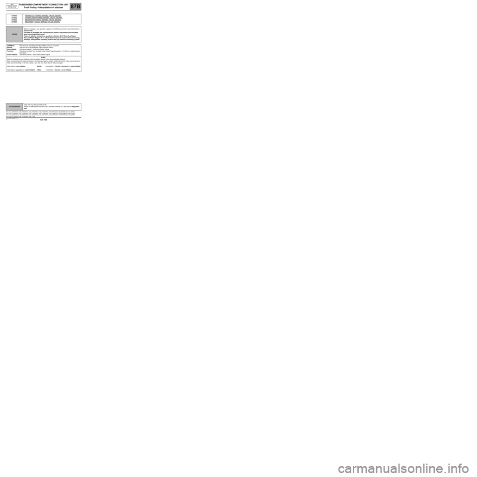
ET032
ET033
ET034
ET035FRONT LEFT-HAND WHEEL VALVE SIGNAL
FRONT RIGHT-HAND WHEEL VALVE SIGNAL
REAR RIGHT-HAND WHEEL VALVE SIGNAL
REAR LEFT-HAND WHEEL VALVE SIGNAL
NOTESBefore carrying out any operation, apply the fault finding procedure (see Introduction).
Special note:
If a wheel is equipped with a tyre pressure sensor, precautions must be taken
when removing/refitting tyres.
Failure to take the precautions specified in Section 35 of Workshop Repair
Manual 364 (for Mégane II) or 370 (for Scénic II) could result in the sensor being
damaged, and potential operating faults in the tyre pressure monitoring system.
CORRECT:The sensor is operating correctly and the pressure is correct.
Absent:The UCH is not receiving the signal from the sensor.
Over-inflated:The sensor sends a "tyre over-inflated" signal.
Puncture:The sensor sends a "tyre severely under-inflated" signal (pressure - 0.6 bar) or a rapid pressure
loss signal.
Under-inflated:The sensor sends a "tyre under-inflated" signal.
STEP 1
Start by checking the tyre inflation and if necessary restore to the recommended pressure.
Next, to ensure that the wheel sensors are functioning properly, at each conformity check, make sure all sensors
really are transmitting. To do this, create a tyre leak and check that its status changes:
Initial status = over-inflated deflate Final status = Correct or puncture or under-inflated
Initial status = puncture or under-inflated inflate Final status = Correct or over-inflated
AFTER REPAIRDeal with any other possible faults.
Switch off the ignition and carry out a road test followed by a test with the diagnostic
tool.
UCH_V44_ET032/UCH_V48_ET032/UCH_V4C_ET032/UCH_V4D_ET032/UCH_V4F_ET032/UCH_V50_ET032/UCH_V44_ET033/
UCH_V48_ET033/UCH_V4C_ET033/UCH_V4D_ET033/UCH_V4F_ET033/UCH_V50_ET033/UCH_V44_ET034/UCH_V48_ET034/
UCH_V4C_ET034/UCH_V4D_ET034/UCH_V4F_ET034/UCH_V50_ET034/UCH_V44_ET035/UCH_V48_ET035/UCH_V4C_ET035/
UCH_V4D_ET035/UCH_V4F_ET035/UCH_V50_ET035
Page 159 of 391
PASSENGER COMPARTMENT CONNECTION UNIT
Fault finding - Interpretation of statuses
87B
87B -159
PASSENGER COMPARTMENT CONNECTION UNIT
Fault finding - Interpretation of statuses
87B
87B -159V9 MR-372-J84-87B000$473.mif
UCH
Vdiag No.: 44, 48,
4C, 4D, 4F, 50
ET032
ET033
ET034
ET035
CONTINUED
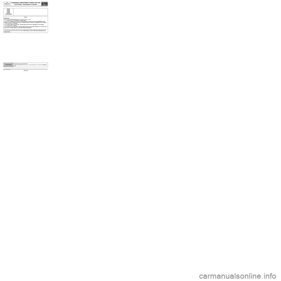
STEP 2
IMPORTANT:
Wait 1 minute and 30 seconds before checking the change of status.
–If the original status is: over-inflated or under-inflated
Consult ALP 52 "Adjust tyre pressure" message appears (the wheel concerned is highlighted on the
display) and ALP 56 "Adjust tyre pressure" message appears (2 wheels are highlighted on the display).
–If the original status is: puncture
Consult ALP 56 "Stop! Tyre puncture" message appears (the wheel is highlighted on the display).
–If the original status is: absent
Consult ALP 54 "Tyre sensor fault" message appears (wheel warning light disappears) and ALP 55 "Tyre
sensor fault" message appears (4 wheel warning lights disappear).
If the status does not change, replace the sensor on the wheel concerned by following the instructions and the
programming procedure for the four valve codes, SC002 Program 4 valve codes (see Configurations and
programming).
AFTER REPAIRDeal with any other possible faults.
Switch off the ignition and carry out a road test followed by a test with the diagnostic
tool.
Page 160 of 391
PASSENGER COMPARTMENT CONNECTION UNIT
Fault finding - Interpretation of statuses
87B
87B -160
PASSENGER COMPARTMENT CONNECTION UNIT
Fault finding - Interpretation of statuses
87B
87B -160V9 MR-372-J84-87B000$473.mif
UCH
Vdiag No.: 44, 48,
4C, 4D, 4F, 50
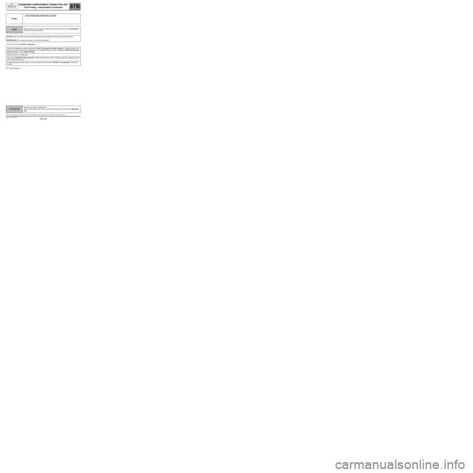
In the event that status ET040 is inoperative:
RF*: Radio frequency.
ET040TYRE PRESSURE MONITOR SYSTEM
NOTESBefore carrying out any operation, apply the fault finding procedure (see Introduction).
Check that no fault is present.
ACTIVE: If the four wheel valves transmit their signal and if the signal is correctly received by the UCH.
INOPERATIVE: If a component is faulty or incorrectly configured.
Check the configuration reading to ensure that LC017 Tyre pressure monitor function is correctly entered in the
UCH. If this is not the case, start configuration in the "Programming" menu with configuration CF023 Tyre pressure
monitor function, under SC008 UCH type.
Check that there is no ABS fault.
Check status ET045 RF* frame received to make sure the receiver aerial is working properly by requesting central
door locking with the card.
If, after performing all these checks, no fault has been found and status ET040 is still Inoperative, contact the
Techline.
AFTER REPAIRDeal with any other possible faults.
Switch off the ignition and carry out a road test followed by a test with the diagnostic
tool.
UCH_V44_ET040/UCH_V48_ET040/UCH_V4C_ET040/UCH_V4D_ET040/UCH_V4F_ET040 / UCH_V50_ET040
Page 161 of 391
PASSENGER COMPARTMENT CONNECTION UNIT
Fault finding - Interpretation of statuses
87B
87B -161
PASSENGER COMPARTMENT CONNECTION UNIT
Fault finding - Interpretation of statuses
87B
87B -161V9 MR-372-J84-87B000$473.mif
UCH
Vdiag No.: 44, 48,
4C, 4D, 4F, 50
ET042
PASSENGER DOOR
NOTESThere must be no faults present.
Use Wiring Diagrams Technical Note for MEGANE II or SCENIC II.
Check the condition and connection of the PE1 connector of the UCH (tabs bent, broken, oxidised etc.).
If the connector is faulty and if there is a repair method (see Technical Note 6015A, Repairing electrical wiring,
Wiring: Precautions for repair), repair the connector; otherwise, replace the wiring.
Check the condition and connection of the passenger's side door lock connector (bent, broken, oxidised tabs, etc.).
If the connector is faulty and if there is a repair method (see Technical Note 6015A, Repairing electrical wiring,
Wiring: Precautions for repair), repair the connector; otherwise, replace the wiring.
Check the insulation and continuity of the following connection:
●Connection code 87G between components 645 and 141.
If the connection is faulty and there is a repair procedure (see Technical Note 6015A, Electrical wiring repair,
Wiring: Precautions for repair), repair the wiring, otherwise replace it.
Check:
The continuity between connections 87G and MAN of component 141 (in the rest position).
The insulation between connections 87G and MAN of component 141 (in the engaged position).
Replace the lock if it is not correct.
In case of inconsistency, contact the Techline.
AFTER REPAIRCarry out another fault finding check on the system.
Clear the stored faults.
Deal with any other faults.
UCH_V44_ET042/UCH_V48_ET042/ UCH_V4C_ET042/
UCH_V4D_ET042 /UCH_V4F_ET042/UCH_V50_ET042
Page 163 of 391
PASSENGER COMPARTMENT CONNECTION UNIT
Fault finding - Interpretation of statuses
87B
87B -163
PASSENGER COMPARTMENT CONNECTION UNIT
Fault finding - Interpretation of statuses
87B
87B -163V9 MR-372-J84-87B000$473.mif
UCH
Vdiag No.: 44, 48,
4C, 4D, 4F, 50
*CPE: Electric central door lockingET044
CPE* BUTTON
NOTESThere must be no present or stored faults.
Use Wiring Diagrams Technical Note for MEGANE II or SCENIC II.
Check the condition and connection of the PE1 connector of the UCH (tabs bent, broken, oxidised etc.).
If the connector is faulty and if there is a repair method (see Technical Note 6015A, Repairing electrical wiring,
Wiring: Precautions for repair), repair the connector; otherwise, replace the wiring.
Check the condition and connection of the connector of the Electric central door locking switch (tabs bent,
broken, oxidised, etc.).
If the connector is faulty and if there is a repair method (see Technical Note 6015A, Repairing electrical wiring,
Wiring: Precautions for repair), repair the connector; otherwise, replace the wiring.
Check the insulation and continuity of the following connections:
●Connection code 20AW,
●Connection code 20M between components 645 and 1391.
If the connection or connections are faulty and there is a repair procedure (see Technical Note 6015A, Electrical
wiring repair, Wiring: Precautions for repair), repair the wiring, otherwise replace it.
Check the insulation and continuity of the following connection:
●Connection code MAM between component 1391 and earth.
If the connection is faulty and there is a repair procedure (see Technical Note 6015A, Electrical wiring repair,
Wiring: Precautions for repair), repair the wiring, otherwise replace it.
Check:
–The continuity of the following connections (switch pressed):
●Connection code 20M,
●Connection code 20AW of component 1391.
–The insulation of the following connections (switch in rest position):
●Connection code 20M,
●Connection code 20AW of component 1391.
Replace the switch if it is not correct.
If the fault is still present, contact the Techline.
AFTER REPAIRCarry out another fault finding check on the system.
Clear the stored faults.
Deal with any other faults.
UCH_V44_ET044/UCH_V48_ET044/ UCH_V4C_ET044/
UCH_V4D_ET044 /UCH_V4F_ET044/UCH_V50_ET044
Page 168 of 391
PASSENGER COMPARTMENT CONNECTION UNIT
Fault finding - Interpretation of statuses
87B
87B -168
PASSENGER COMPARTMENT CONNECTION UNIT
Fault finding - Interpretation of statuses
87B
87B -168V9 MR-372-J84-87B000$473.mif
UCH
Vdiag No.: 44, 48,
4C, 4D, 4F, 50
ET047
CONTINUED 2
ET047 Inconsistency without depressing the pedal.
Check the condition and connection of the brake pedal switch connector.
If the connector is faulty and if there is a repair method (see Technical Note 6015A, Repairing electrical wiring,
Wiring: Precautions for repair), repair the connector; otherwise, replace the wiring.
With the brake pedal switch disconnected:
Check the insulation between connections 65A and SP17 of component 160 (brake light switch piston pressed).
Only replace the brake pedal switch if it is not correct.
Check the condition and connection of the UCH connector PE2.
If the connector is faulty and if there is a repair method (see Technical Note 6015A, Repairing electrical wiring,
Wiring: Precautions for repair), repair the connector; otherwise, replace the wiring.
With the UCH and brake pedal switch disconnected:
Check the insulation in relation to + 12 V of connection 5A between components 645 and 160.
The line is shared with the ABS computer or the electronic stability program (ESP) relay (depending on equipment)
and the brake lights.
In the event of faulty insulation, use a wiring diagram to check the connections between the brake pedal switch
connector and these components.
If the fault is still present, contact the Techline.
AFTER REPAIRCarry out another fault finding check on the system.
Clear the stored faults.
Deal with any other faults.
Page 169 of 391
PASSENGER COMPARTMENT CONNECTION UNIT
Fault finding - Interpretation of statuses
87B
87B -169
PASSENGER COMPARTMENT CONNECTION UNIT
Fault finding - Interpretation of statuses
87B
87B -169V9 MR-372-J84-87B000$473.mif
UCH
Vdiag No.: 44, 48,
4C, 4D, 4F, 50
ET047
CONTINUED 3
ET047 Undetermined with the pedal depressed.
Check the condition and connection of the brake pedal switch connector.
If the connector is faulty and if there is a repair method (see Technical Note 6015A, Repairing electrical wiring,
Wiring: Precautions for repair), repair the connector; otherwise, replace the wiring.
With the brake pedal switch disconnected:
Check for + 12 V on component 160 on connection SP17.
If not correct:
–Check the condition and connection of fuse 1H in the passenger compartment relay and fuse box.
–Check the condition and the connection of the passenger compartment fuse and relay box connector. If the
connector is faulty and if there is a repair method (see Technical Note 6015A, Repairing electrical wiring,
Wiring: Precautions for repair), repair the connector; otherwise, replace the wiring.
–Check the insulation and continuity of connection SP17 between components 160 and 260. If the connection
is faulty and there is a repair procedure (see Technical Note 6015A, Electrical wiring repair, Wiring:
Precautions for repair), repair the wiring, otherwise replace it.
If it is still faulty, contact Techline.
With the brake pedal switch disconnected:
Check the continuity of the following connections:
●Connection code 65A,
●Connection code SP17 of component 160 (brake pedal switch piston free).
Only replace the brake pedal switch if it is not correct.
Check the condition and connection of the UCH connector PE2.
If the connector is faulty and if there is a repair method (see Technical Note 6015A, Repairing electrical wiring,
Wiring: Precautions for repair), repair the connector; otherwise, replace the wiring.
With the UCH and brake pedal switch disconnected:
Check the insulation and continuity of the following connection:
●Connection code 65A between components 645 and 160.
If the connection is faulty and there is a repair procedure (see Technical Note 6015A, Electrical wiring repair,
Wiring: Precautions for repair), repair the wiring, otherwise replace it.
The line is shared with the ABS computer or the ESP relay (depending on equipment) and the brake lights. In the
event of faulty insulation, it is therefore necessary, using a wiring diagram, to check the connections between the
brake pedal switch connector and these components.
AFTER REPAIRCarry out another fault finding check on the system.
Clear the stored faults.
Deal with any other faults.
Page 172 of 391
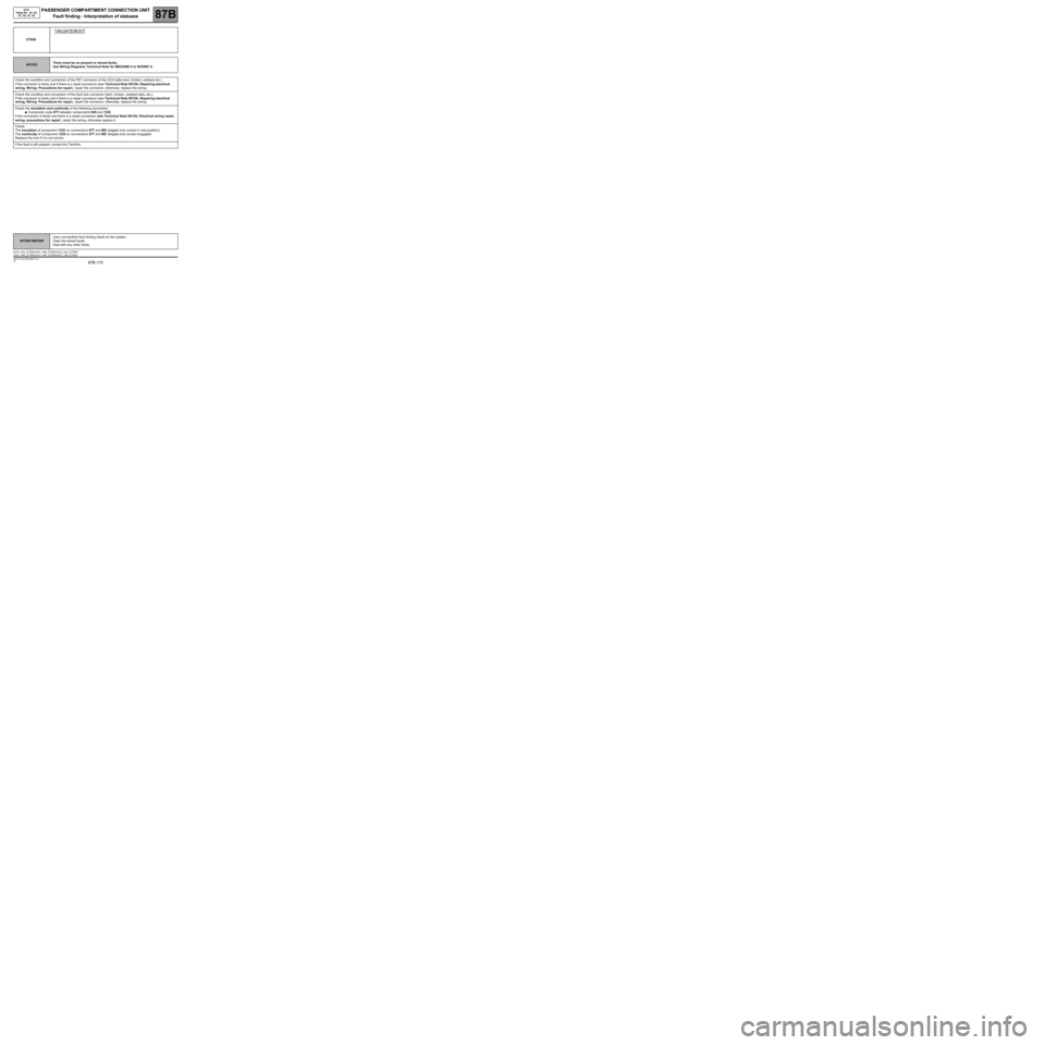
PASSENGER COMPARTMENT CONNECTION UNIT
Fault finding - Interpretation of statuses
87B
87B -172
PASSENGER COMPARTMENT CONNECTION UNIT
Fault finding - Interpretation of statuses
87B
87B -172V9 MR-372-J84-87B000$473.mif
UCH
Vdiag No.: 44, 48,
4C, 4D, 4F, 50
ET050
TAILGATE/BOOT
NOTESThere must be no present or stored faults.
Use Wiring Diagrams Technical Note for MEGANE II or SCENIC II.
Check the condition and connection of the PE1 connector of the UCH (tabs bent, broken, oxidised etc.).
If the connector is faulty and if there is a repair procedure (see Technical Note 6015A, Repairing electrical
wiring, Wiring: Precautions for repair), repair the connector; otherwise, replace the wiring.
Check the condition and connection of the boot lock connector (bent, broken, oxidised tabs, etc.).
If the connector is faulty and if there is a repair procedure (see Technical Note 6015A, Repairing electrical
wiring, Wiring: Precautions for repair), repair the connector; otherwise, replace the wiring.
Check the insulation and continuity of the following connection:
●Connection code 87T between components 645 and 1322.
If the connection is faulty and there is a repair procedure (see Technical Note 6015A, Electrical wiring repair,
wiring: precautions for repair), repair the wiring, otherwise replace it.
Check:
The insulation of component 1332 on connections 87T and MZ (tailgate lock contact in rest position).
The continuity of component 1332 on connections 87T and MZ (tailgate lock contact engaged).
Replace the lock if it is not correct.
If the fault is still present, contact the Techline.
AFTER REPAIRCarry out another fault finding check on the system.
Clear the stored faults.
Deal with any other faults.
UCH_V44_ET050/UCH_V48_ET050/ UCH_V4C_ET050/
UCH_V4D_ET050 /UCH_V4F_ET050/UCH_V50_ET050
Page 173 of 391
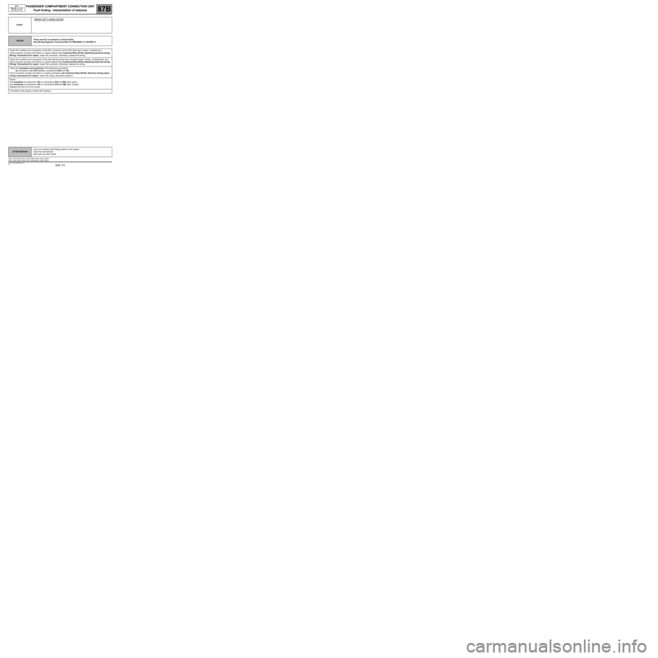
PASSENGER COMPARTMENT CONNECTION UNIT
Fault finding - Interpretation of statuses
87B
87B -173
PASSENGER COMPARTMENT CONNECTION UNIT
Fault finding - Interpretation of statuses
87B
87B -173V9 MR-372-J84-87B000$473.mif
UCH
Vdiag No.: 44, 48,
4C, 4D, 4F, 50
ET051
REAR LEFT-HAND DOOR
NOTESThere must be no present or stored faults.
Use Wiring Diagrams Technical Note for MEGANE II or SCENIC II.
Check the condition and connection of the PE1 connector of the UCH (tabs bent, broken, oxidised etc.).
If the connector is faulty and if there is a repair method (see Technical Note 6015A, Repairing electrical wiring,
Wiring: Precautions for repair), repair the connector; otherwise, replace the wiring.
Check the condition and connection of the rear left-hand door lock connector (bent, broken, oxidised tabs, etc.).
If the connector is faulty and if there is a repair method (see Technical Note 6015A, Repairing electrical wiring,
Wiring: Precautions for repair), repair the connector; otherwise, replace the wiring.
Check the insulation and continuity of the following connection:
●Connection code 87A between components 645 and 139.
If the connection is faulty and there is a repair procedure (see Technical Note 6015A, Electrical wiring repair,
wiring: precautions for repair), repair the wiring, otherwise replace it.
Check:
The insulation of component 139 on connections 87A and MZ (door open).
The continuity of component 139 on connections 87A and MZ (door closed).
Replace the lock if it is not correct.
If the fault is still present, contact the Techline.
AFTER REPAIRCarry out another fault finding check on the system.
Clear the stored faults.
Deal with any other faults.
UCH_V44_ET051/UCH_V48_ET051/ UCH_V4C_ET051/
UCH_V4D_ET051 /UCH_V4F_ET051/UCH_V50_ET051