ignition RENAULT SCENIC 2008 J84 / 2.G Passenger Comparment Connection Unit Repair Manual
[x] Cancel search | Manufacturer: RENAULT, Model Year: 2008, Model line: SCENIC, Model: RENAULT SCENIC 2008 J84 / 2.GPages: 391
Page 184 of 391
PASSENGER COMPARTMENT CONNECTION UNIT
Fault finding - Interpretation of statuses87B
87B - 184
PASSENGER COMPARTMENT CONNECTION UNIT
Fault finding - Interpretation of statuses87B
87B - 184V9 MR-372-J84-87B000$516.mif
UCH
Vdiag No.: 44, 48,
4C, 4D, 4F, 50
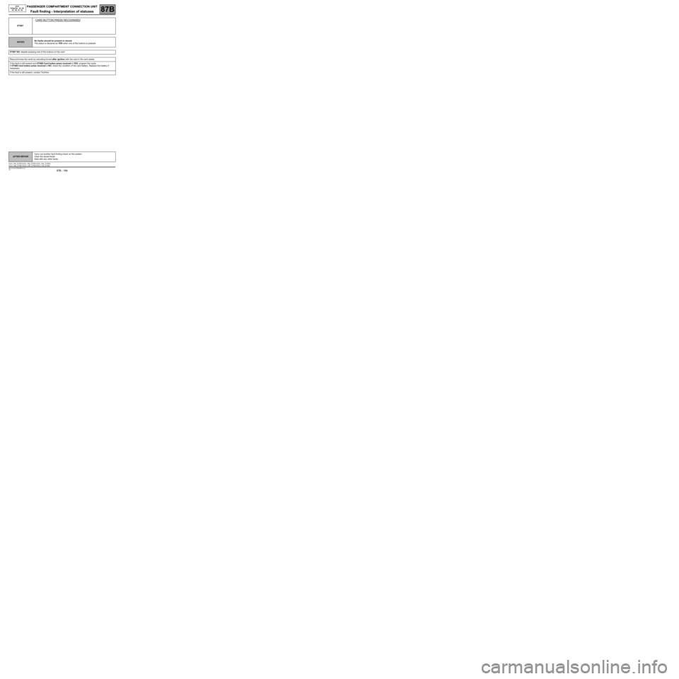
ET067
CARD BUTTON PRESS RECOGNISED
NOTESNo faults should be present or stored.
The status is declared as YES when one of the buttons is pressed.
ET067 NO, despite pressing one of the buttons on the card.
Resynchronise the cards by activating forced after ignition with the card in the card reader.
If the fault is still present and ET066 Card button press received is YES, program the cards.
If ET066 Card button press received is NO, check the condition of the card battery. Replace the battery if
necessary.
If the fault is still present, contact Techline.
AFTER REPAIRCarry out another fault finding check on the system.
Clear the stored faults.
Deal with any other faults.
UCH_V44_ET067/UCH_V48_ET067/ UCH_V4C_ET067/
UCH_V4D_ET067 /UCH_V4F_ET067/UCH_V50_ET067
Page 190 of 391
PASSENGER COMPARTMENT CONNECTION UNIT
Fault finding - Interpretation of statuses87B
87B - 190
PASSENGER COMPARTMENT CONNECTION UNIT
Fault finding - Interpretation of statuses87B
87B - 190V9 MR-372-J84-87B000$516.mif
UCH
Vdiag No.: 44, 48,
4C, 4D, 4F, 50
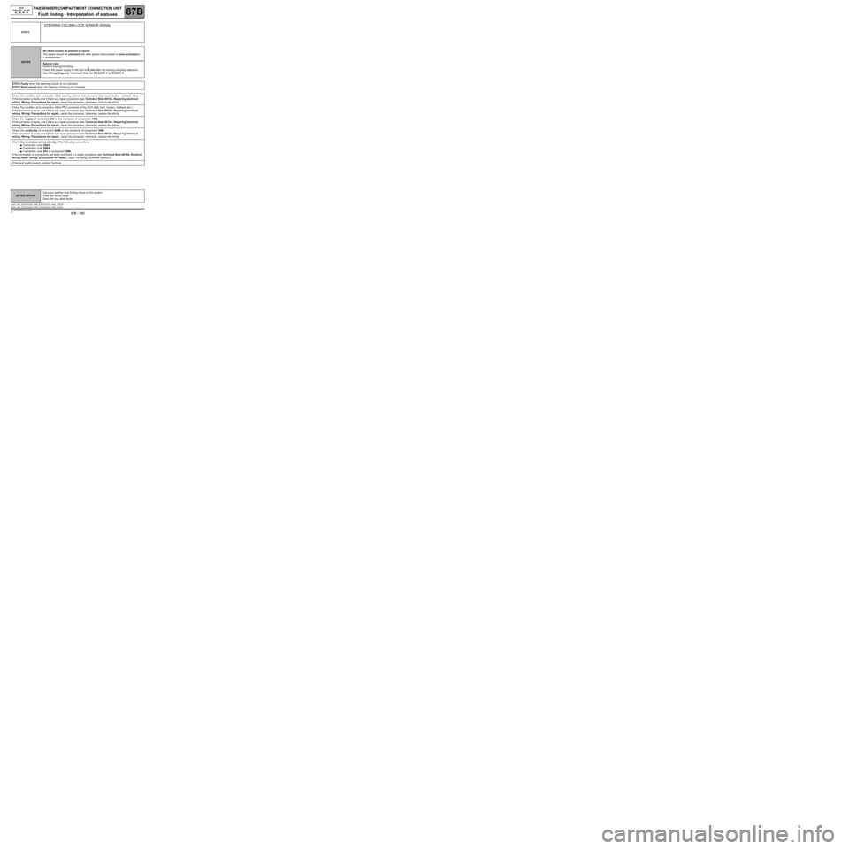
ET073
STEERING COLUMN LOCK SENSOR SIGNAL
NOTESNo faults should be present or stored.
The status should be unlocked with after ignition feed present or semi activated to
+ accessories.
Special note:
Perform locking/unlocking.
Check the power supply to the lock for 5 min after the locking-unlocking operation.
Use Wiring Diagrams Technical Note for MEGANE II or SCENIC II.
ET073 Faulty when the steering column is not unlocked.
ET073 Short circuit when the steering column is not unlocked.
Check the condition and connection of the steering column lock connector (tabs bent, broken, oxidised, etc.).
If the connector is faulty and if there is a repair procedure (see Technical Note 6015A, Repairing electrical
wiring, Wiring: Precautions for repair), repair the connector; otherwise, replace the wiring.
Check the condition and connection of the PE2 connector of the UCH (tabs bent, broken, oxidised, etc.).
If the connector is faulty and if there is a repair procedure (see Technical Note 6015A, Repairing electrical
wiring, Wiring: Precautions for repair), repair the connector; otherwise, replace the wiring.
Check the supply of connection 26I on the connector of component 1088.
If the connector is faulty and if there is a repair procedure (see Technical Note 6015A, Repairing electrical
wiring, Wiring: Precautions for repair), repair the connector; otherwise, replace the wiring.
Check the continuity of connection NAM on the connector of component 1088.
If the connector is faulty and if there is a repair procedure (see Technical Note 6015A, Repairing electrical
wiring, Wiring: Precautions for repair), repair the connector; otherwise, replace the wiring.
Check the insulation and continuity of the following connections:
●Connection code 26AZ,
●Connection code 26BA,
●Connection code 26J of component 1088.
If the connection or connections are faulty and there is a repair procedure (see Technical Note 6015A, Electrical
wiring repair, wiring: precautions for repair), repair the wiring, otherwise replace it.
If the fault is still present, contact Techline.
AFTER REPAIRCarry out another fault finding check on the system.
Clear the stored faults.
Deal with any other faults.
UCH_V44_ET073/UCH_V48_ET073/ UCH_V4C_ET073/
UCH_V4D_ET073 /UCH_V4F_ET073/UCH_V50_ET073
Page 191 of 391
PASSENGER COMPARTMENT CONNECTION UNIT
Fault finding - Interpretation of statuses87B
87B - 191
PASSENGER COMPARTMENT CONNECTION UNIT
Fault finding - Interpretation of statuses87B
87B - 191V9 MR-372-J84-87B000$516.mif
UCH
Vdiag No.: 44, 48,
4C, 4D, 4F, 50
ET073
CONTINUED
ET073 Unlocked and + after ignition absent.
The status remains UNLOCKED, with the ignition off, in case of failure of the airbag system or the speed signal. If
everything is OK, see dealing with fault DF029: Steering column lock circuit.
ET073 Semi-activated and + after ignition present.
In the semi-activated status, the lock bolt is pulled out, but the UCH cannot determine its position precisely.
In case of inconsistency, contact the Techline.
ET073 Undetermined.
The status is Undetermined. in the event that neither the steering column lock nor the lock sensor can inform the
UCH regarding its position.
Refer to processing of the DF029 Steering column lock circuit fault.
AFTER REPAIRCarry out another fault finding check on the system.
Clear the stored faults.
Deal with any other faults.
Page 192 of 391
PASSENGER COMPARTMENT CONNECTION UNIT
Fault finding - Interpretation of statuses87B
87B - 192
PASSENGER COMPARTMENT CONNECTION UNIT
Fault finding - Interpretation of statuses87B
87B - 192V9 MR-372-J84-87B000$516.mif
UCH
Vdiag No.: 44, 48,
4C, 4D, 4F, 50
ET075
+ ACCESSORIES PRESENT
NOTESNo faults should be present or stored.
Special note:
Check that the start switch operates correctly: ET070 Start button.
Use Wiring Diagrams Technical Note for MEGANE II or SCENIC II.
ET075 is YES but + accessories is absent.
Check for + 12 V on component 260 (on the left-hand side of the centre console) on connection BP11 (track E1).
If the connector is faulty and if there is a repair procedure (see Technical Note 6015A, Repairing electrical
wiring, Wiring: Precautions for repair), repair the connector; otherwise, replace the wiring.
Check the power-supply fuses.
Check that there is no + 12 V on connection S of component 645 (with + after ignition feed).
If NO, contact the techline.
If YES, check the continuity of the following connection:
●Connection code S between components 645 and 260.
If the connection is faulty and there is a repair procedure (see Technical Note 6015A, Electrical wiring repair,
Wiring: Precautions for repair), repair the wiring, otherwise replace it.
AFTER REPAIRCarry out another fault finding check on the system.
Clear the stored faults.
Deal with any other faults.
UCH_V44_ET075/UCH_V48_ET075/ UCH_V4C_ET075/
UCH_V4D_ET075 /UCH_V4F_ET075/UCH_V50_ET075
Page 215 of 391
PASSENGER COMPARTMENT CONNECTION UNIT
Fault finding - Interpretation of statuses87B
87B - 215
PASSENGER COMPARTMENT CONNECTION UNIT
Fault finding - Interpretation of statuses87B
87B - 215V9 MR-372-J84-87B000$559.mif
UCH
Vdiag No.: 44, 48,
4C, 4D, 4F, 50
*CPE: Electric central door locking.ET088
ET090
SOURCE OF DEADLOCK ACTIVATION
SOURCE OF DEADLOCK DEACTIVATION
NOTESNo faults should be present or stored.
Enables determination of what component is the source of the last locking or unlocking operation.
ET088.
CARD: upon pressing the card for the second time.
HANDS-FREE: on pressing the door handle button for the second time.
FAULT FINDING: using the diagnostic tool, with the ignition on and running command AC004 Central locking
of doors and boot.
ET090.
CPE*: on pressing the locking/unlocking button.
CARD: press on card button.
HANDS-FREE: placing a hand in the handle.
FAULT FINDING: using the diagnostic tool, with the ignition on and running command AC005 Central door
unlocking.
+ after ignition feed: no deadlocking at this power supply level.
AFTER REPAIRCarry out another fault finding check on the system.
Clear the stored faults.
Deal with any other faults.
UCH_V44_ET088/UCH_V48_ET088/ UCH_V4C_ET088/UCH_V4D_ET088/ UCH_V4F_ET088/UCH_V50_ET088/
UCH_V44_ET090/UCH_V48_ET090/ UCH_V4C_ET090/UCH_V4D_ET090/ UCH_V4F_ET090/UCH_V50_ET090
Page 226 of 391
PASSENGER COMPARTMENT CONNECTION UNIT
Fault finding - Interpretation of statuses87B
87B - 226
PASSENGER COMPARTMENT CONNECTION UNIT
Fault finding - Interpretation of statuses87B
87B - 226V9 MR-372-J84-87B000$559.mif
UCH
Vdiag No.: 44, 48,
4C, 4D, 4F, 50
ET110
UCH REQUEST TO INJECTION COMPUTER OR PROTECTION
AND SWITCHING UNIT
NOTESNo faults should be present or stored.
This status gives information concerning the type of request made by the UCH to these computers.
"ENGINE STOP": when an engine stop is requested.
"INACTIVE": without action on the vehicle.
"+ AFTER IGNITION FEED": on pressing the start button for more than 5 seconds.
"START": when starting is requested.
If the status does not correspond to the current user request, carry out a test of the multiplex network.
If the fault is still present, contact Techline.
AFTER REPAIRCarry out another fault finding check on the system.
Clear the stored faults.
Deal with any other faults.
UCH_V44_ET110/UCH_V48_ET110/UCH_V4C_ET110/
UCH_V4D_ET110/UCH_V4F_ET110/UCH_V50_ET110
Page 237 of 391
PASSENGER COMPARTMENT CONNECTION UNIT
Fault finding - Interpretation of statuses87B
87B - 237
PASSENGER COMPARTMENT CONNECTION UNIT
Fault finding - Interpretation of statuses87B
87B - 237V9 MR-372-J84-87B000$602.mif
UCH
Vdiag No.: 44, 48,
4C, 4D, 4F, 50
ET229
INJECTION IMMOBILISER CODE
NOTESNo faults should be present or stored.
Apply the checks only if the status remains INCORRECT after the ignition is switched
off and back on.
INCORRECT
Try to start the vehicle, ensuring that the steering column lock unlocks properly and that
the + after ignition feed has been established on the vehicle using ET014 Control
power level.
First check the operation of status ET046 Engine immobiliser.
Carry out a multiplex network test.
Run fault finding on the injection system.
If the fault is still present, contact the Techline.
AFTER REPAIRCarry out another fault finding check on the system.
Clear the stored faults.
Deal with any other faults.
UCH_V44_ET229/UCH_V48_ET229/ UCH_V4C_ET229/
UCH_V4D_ET229 /UCH_V4F_ET229/UCH_V50_ET229
Page 257 of 391
PASSENGER COMPARTMENT CONNECTION UNIT
Fault finding - Interpretation of commands87B
87B - 257
PASSENGER COMPARTMENT CONNECTION UNIT
Fault finding - Interpretation of commands87B
87B - 257V9 MR-372-J84-87B000$774.mif
UCH
Vdiag No.: 44, 48,
4C, 4D, 4F, 50
AC015
AIR-CONDITIONING BUTTON INDICATOR LIGHT
Manual air conditioning only
NOTESNo faults should be present or stored.
This command is for testing operation of the air-conditioning indicator light.
Apply the after ignition feed, and the air conditioning control panel should light up.
The command lasts 7 seconds.
Use Wiring Diagrams Technical Note for MEGANE II or SCENIC II.
The indicator light does not light up when the command is activated.
Check the condition and connection of the heater control panel connector.
If the connector is faulty and if there is a repair procedure (see Technical Note 6015A, Repairing electrical
wiring, Wiring: Precautions for repair), repair the connector; otherwise, replace the wiring.
Check for earth on connection NAM of component 316.
If the connector is faulty and if there is a repair procedure (see Technical Note 6015A, Repairing electrical
wiring, Wiring: Precautions for repair), repair the connector; otherwise, replace the wiring.
With the command running, check for + 12 V feed on connection 38ES of component 316.
If OK, replace the control panel.
Check the condition and connection of connector PE2 on the UCH
If the connector is faulty and if there is a repair procedure (see Technical Note 6015A, Repairing electrical
wiring, Wiring: Precautions for repair), repair the connector; otherwise, replace the wiring.
Check the insulation and continuity of the following connection:
●Connection code 38ES between components 645 and 319.
●Connection code NAM between component 319 and earth.
If the connection or connections are faulty and there is a repair procedure (see Technical Note 6015A, Electrical
wiring repair, Wiring: Precautions for repair), repair the wiring, otherwise replace it.
If the fault is still present, contact Techline.
AFTER REPAIRCarry out another fault finding check on the system.
Clear the stored faults.
Deal with any other faults.
Page 264 of 391
PASSENGER COMPARTMENT CONNECTION UNIT
Fault finding - Interpretation of commands87B
87B - 264
PASSENGER COMPARTMENT CONNECTION UNIT
Fault finding - Interpretation of commands87B
87B - 264V9 MR-372-J84-87B000$774.mif
UCH
Vdiag No.: 44, 48,
4C, 4D, 4F, 50
AC019
HEATED REAR SCREEN INDICATOR LIGHT
Except with climate control
NOTESNo faults should be present or stored.
This command is for testing operation of the heated rear screen indicator light.
Apply after ignition feed.
The command lasts 7 seconds.
Use Wiring Diagrams Technical Note for MEGANE II or SCENIC II.
The heated rear screen indicator light does not light up when the command is activated.
Check the condition and connection of the heater control panel connector.
If the connector is faulty and if there is a repair procedure (see Technical Note 6015A, Repairing electrical
wiring, Wiring: Precautions for repair), repair the connector; otherwise, replace the wiring.
Check for earth on connection NAM of component 319.
If the connector is faulty and if there is a repair procedure (see Technical Note 6015A, Repairing electrical
wiring, Wiring: Precautions for repair), repair the connector; otherwise, replace the wiring.
With the command running, check for + 12 V feed on connection 15A of component 316.
If OK, replace the control panel.
Check the condition and connection of connector PE2 on the UCH
If the connector is faulty and if there is a repair procedure (see Technical Note 6015A, Repairing electrical
wiring, Wiring: Precautions for repair), repair the connector; otherwise, replace the wiring.
Check the insulation and continuity of the following connection:
●Connection code 15A between components 645 and 319.
If the connection is faulty and there is a repair procedure (see Technical Note 6015A, Electrical wiring repair,
Wiring: Precautions for repair), repair the wiring, otherwise replace it.
If the fault is still present, contact Techline.
AFTER REPAIRCarry out another fault finding check on the system.
Clear the stored faults.
Deal with any other faults.
Page 267 of 391
PASSENGER COMPARTMENT CONNECTION UNIT
Fault finding - Interpretation of commands87B
87B - 267
PASSENGER COMPARTMENT CONNECTION UNIT
Fault finding - Interpretation of commands87B
87B - 267V9 MR-372-J84-87B000$774.mif
UCH
Vdiag No.: 44, 48,
4C, 4D, 4F, 50
AC022
Left-hand direction indicator
NOTESNo faults should be present or stored.
This command is for testing direction indicator operation.
Apply after ignition feed.
Check the bulbs.
Use Wiring Diagrams Technical Note for MEGANE II or SCENIC II.
The direction indicators do not light when the command is activated.
Check the condition and connection of the connectors for the left-hand headlight, the left-hand repeater and the
rear left-hand light.
If the connector is faulty and if there is a repair procedure (see Technical Note 6015A, Repairing electrical
wiring, Wiring: Precautions for repair), repair the connector; otherwise, replace the wiring.
Check for earth on the following connections:
●Connection code MAS.
Between component 227 and earth.
Between component 268 and earth.
●Connection code MZ between component 173 and earth.
If the connection or connections are faulty and there is a repair procedure (see Technical Note 6015A, Electrical
wiring repair, Wiring: Precautions for repair), repair the wiring, otherwise replace it.
Check for the + 12 V feed with the command running on the following connections:
●Connection code 64C.
Between component 227 and earth.
Between component 173 and earth.
●Connection code 64V between component 268 and earth.
If the connection or connections are faulty and there is a repair procedure (see Technical Note 6015A, Electrical
wiring repair, Wiring: Precautions for repair), repair the wiring, otherwise replace it.
If the + 12 V feed is correct, check the bulbs again and if the bulbs still do not work, replace the rear light(s).
Check the condition and connection of the PP3 connector on the UCH.
If the connector is faulty and if there is a repair procedure (see Technical Note 6015A, Repairing electrical
wiring, Wiring: Precautions for repair), repair the connector; otherwise, replace the wiring.
AFTER REPAIRCarry out another fault finding check on the system.
Clear the stored faults.
Deal with any other faults.