low beam RENAULT SCENIC 2008 J84 / 2.G Passenger Comparment Connection Unit Workshop Manual
[x] Cancel search | Manufacturer: RENAULT, Model Year: 2008, Model line: SCENIC, Model: RENAULT SCENIC 2008 J84 / 2.GPages: 391
Page 8 of 391
PASSENGER COMPARTMENT CONNECTION UNIT
Fault finding - System operation
87B
87B-8
PASSENGER COMPARTMENT CONNECTION UNIT
Fault finding - System operation
87B
87B-8V9 MR-372-J84-87B000$086.mif
UCH
Vdiag No.: 44, 48,
4C, 4D, 4F, 50
The ACCESS/SAFETY function is divided into three sub-functions: Access, Protection and Starting.
The maximum number of Renault cards which can be programmed on the vehicle is 4. There is no master Renault
card.
1 ACCESS/SAFETY FUNCTION
1.1 SUB-FUNCTION: ACCESS
The Megane II allows:
–locking/unlocking by pressing the buttons on the Renault card (remote control function),
–locking/unlocking by pressing the central door locking button,
–locking via the Renault Anti-Intruder Device (RAID),
–automatic relocking.
If the vehicle is fitted with the hands-free function:
–hands-free unlocking of the entire vehicle, by cutting the optical beam on one of the door handles,
–hands-free boot-only unlocking by pressing the boot opening switch,
–hands-free locking (by pressing the handle closure switch or the switch located in the boot badge).
If the vehicle is fitted with:
–electric child safety locking,
–deadlocking,
–selective opening element unlocking,
–the valet card function.
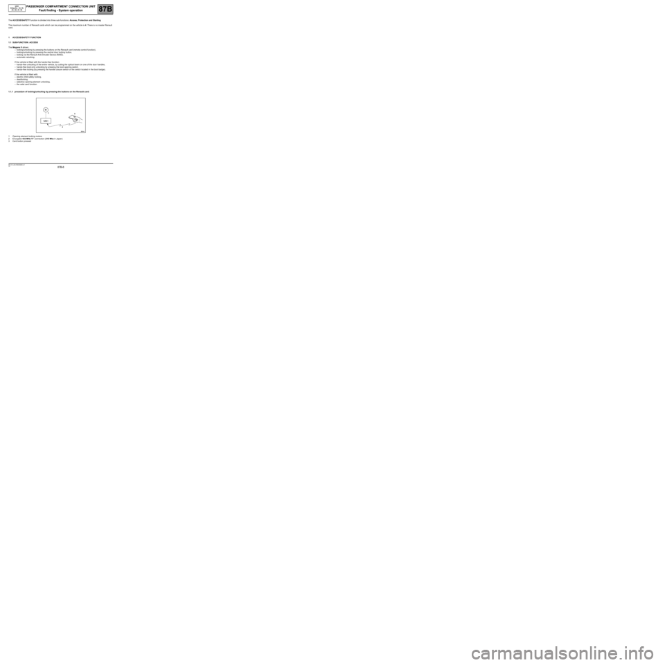
1.1.1 procedure of locking/unlocking by pressing the buttons on the Renault card:
1Opening element locking motors
2Encrypted 433 MHz RF connection (315 Mhz in Japan)
3Card button pressed
Page 40 of 391
PASSENGER COMPARTMENT CONNECTION UNIT
Fault finding - System operation
87B
87B-40
PASSENGER COMPARTMENT CONNECTION UNIT
Fault finding - System operation
87B
87B-40V9 MR-372-J84-87B000$129.mif
UCH
Vdiag No.: 44, 48,
4C, 4D, 4F, 50
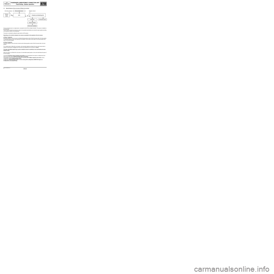
3.3 Special features of the rain sensor (if fitted to the vehicle)
The rain and light sensor is a single sensor, connected to the UCH by a single connection. This sensor is installed on
the windscreen.
The rain sensor enables the windscreen wipers to be operated automatically and controls the wiper speeds according
to the quantity of water on the windscreen.
The sensor is activated by setting the wiper stalk to AUTO position.
Depending on the vehicle's bodywork, two cases are possible for the operation of the rain sensor:
a) Phase 1 bodywork:
Automatic operation of the rain sensor is inhibited following ignition switch-off with the wiper stalk in the Auto position.
To reactivate operation when next switching on the ignition, set the wiper control stalk in the neutral position then
return it to the Auto position.
b) Phase 2 bodywork:
Automatic operation of the rain sensor remains active following ignition switch-off with the wiper stalk in the Auto
position.
For a vehicle which is fitted with a rain sensor, with automatic detection activated, the rear screen wiper starts to
operate if reverse gear is engaged and if the sensor has detected rain for more than 1 minute.
The wiper intermittent speed ring is used to modify the sensor's sensitivity to rain and therefore the time
between wipes.
When the vehicle is not fitted with a rain sensor, the intermittent speed position on the control stalk takes the place of
the Auto position.
The status ET118 Rain sensor sensitivity ring position can be interpreted if the vehicle is configured with rain
sensor and inhibits status ET096 Intermittent wipe ring position.
The operation of the rain sensor can be displayed using status ET114 Wiper request by rain sensor, and by
configuration reading LC044 Rain/light sensor.
Configuration CF035 Rain/light sensor is available during UCH configuration (SC008 UCH type) (see
Configurations and programming). Information displays Rain and light sensor Multiplex network
Steering
column
control UCH Protection and Switching Unit
Side lights Windscreen wiper
Dipped headlights
Main beam headlights
Page 43 of 391
PASSENGER COMPARTMENT CONNECTION UNIT
Fault finding - System operation
87B
87B-43
PASSENGER COMPARTMENT CONNECTION UNIT
Fault finding - System operation
87B
87B-43V9 MR-372-J84-87B000$129.mif
UCH
Vdiag No.: 44, 48,
4C, 4D, 4F, 50
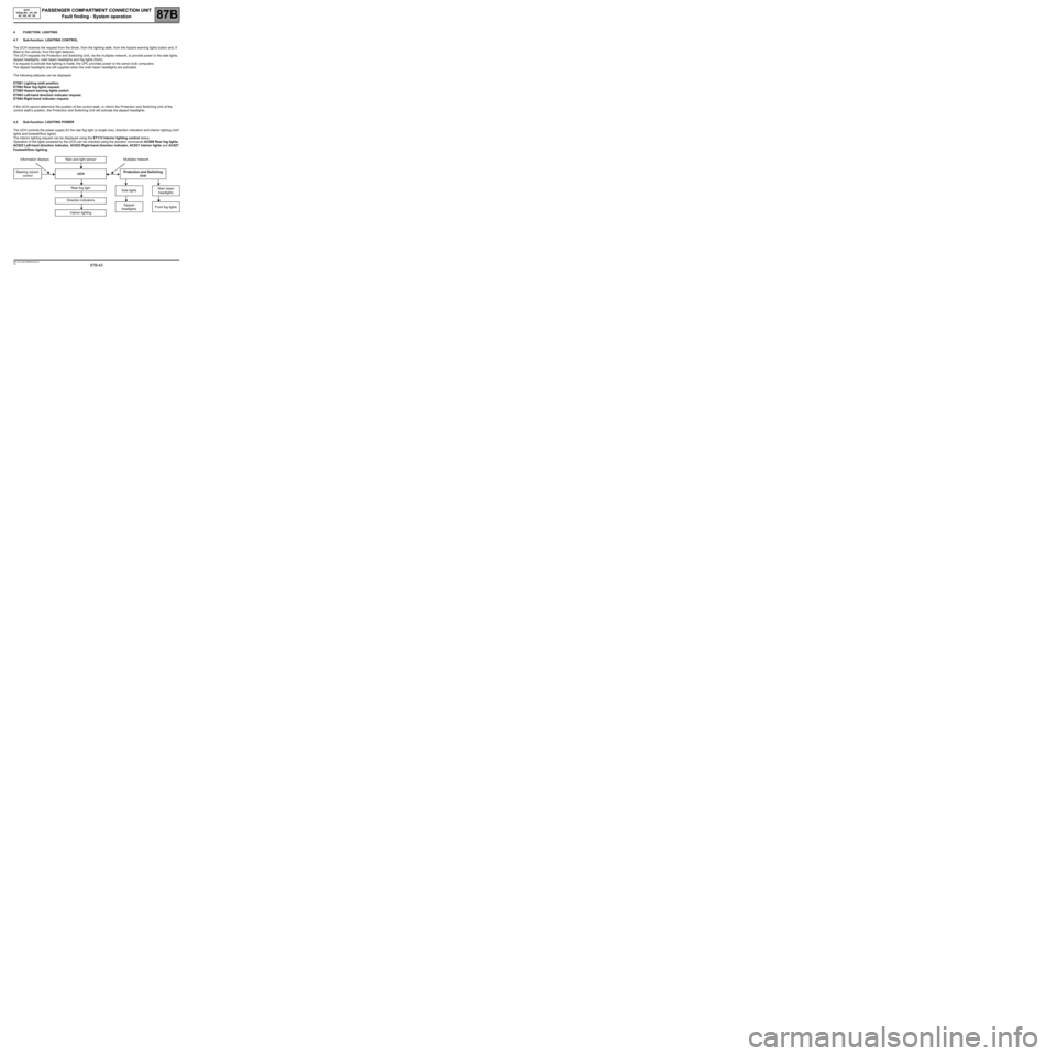
4FUNCTION: LIGHTING
4.1 Sub-function: LIGHTING CONTROL
The UCH receives the request from the driver, from the lighting stalk, from the hazard warning lights button and, if
fitted to the vehicle, from the light detector.
The UCH requests the Protection and Switching Unit, via the multiplex network, to provide power to the side lights,
dipped headlights, main beam headlights and fog lights (front).
If a request to activate the lighting is made, the UPC provides power to the xenon bulb computers.
The dipped headlights are still supplied when the main beam headlights are activated.
The following statuses can be displayed:
ET081 Lighting stalk position.
ET082 Rear fog lights request.
ET085 Hazard warning lights switch.
ET083 Left-hand direction indicator request.
ET084 Right-hand indicator request.
If the UCH cannot determine the position of the control stalk, or inform the Protection and Switching Unit of the
control stalk's position, the Protection and Switching Unit will activate the dipped headlights.
4.2 Sub-function: LIGHTING POWER
The UCH controls the power supply for the rear fog light (a single one), direction indicators and interior lighting (roof
lights and footwell/floor lights).
The interior lighting request can be displayed using the ET112 Interior lighting control status.
Operation of the lights powered by the UCH can be checked using the actuator commands AC009 Rear fog lights,
AC022 Left-hand direction indicator, AC023 Right-hand direction indicator, AC021 Interior lights and AC027
Footwell/floor lighting.
Information displays Rain and light sensor Multiplex network
Steering column
controlUCHProtection and Switching
Unit
Rear fog light
Direction indicators
Interior lighting
Side lightsMain beam
headlights
Dipped
headlightsFront fog lights
Page 198 of 391
PASSENGER COMPARTMENT CONNECTION UNIT
Fault finding - Interpretation of statuses87B
87B - 198
PASSENGER COMPARTMENT CONNECTION UNIT
Fault finding - Interpretation of statuses87B
87B - 198V9 MR-372-J84-87B000$516.mif
UCH
Vdiag No.: 44, 48,
4C, 4D, 4F, 50
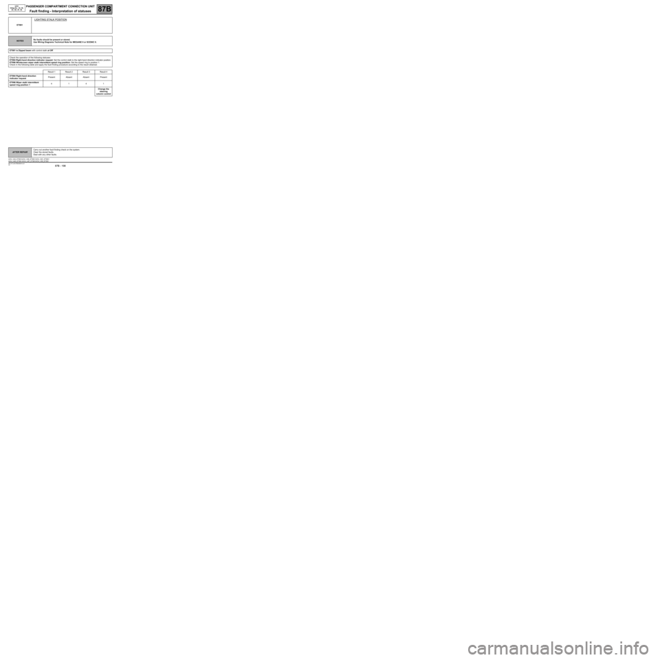
ET081
LIGHTING STALK POSITION
NOTESNo faults should be present or stored.
Use Wiring Diagrams Technical Note for MEGANE II or SCENIC II.
ET081 is Dipped beam with control stalk at Off.
Check the operation of the following statuses:
ET084 Right-hand direction indicator request: Set the control stalk to the right-hand direction indicator position.
ET096 Windscreen wiper stalk intermittent speed ring position: Set the speed ring to position 1.
Check in the following table and apply the fault finding procedure according to the result obtained.
Result 1 Result 2 Result 3 Result 4
ET084 Right-hand direction
indicator requestPresent Absent Absent Present
ET096 Wiper stalk intermittent
speed ring position 14141
Change the
steering
column control
AFTER REPAIRCarry out another fault finding check on the system.
Clear the stored faults.
Deal with any other faults.
UCH_V44_ET081/UCH_V48_ET081/ UCH_V4C_ET081/
UCH_V4D_ET081 /UCH_V4F_ET081/UCH_V50_ET081
Page 200 of 391
PASSENGER COMPARTMENT CONNECTION UNIT
Fault finding - Interpretation of statuses87B
87B - 200
PASSENGER COMPARTMENT CONNECTION UNIT
Fault finding - Interpretation of statuses87B
87B - 200V9 MR-372-J84-87B000$516.mif
UCH
Vdiag No.: 44, 48,
4C, 4D, 4F, 50
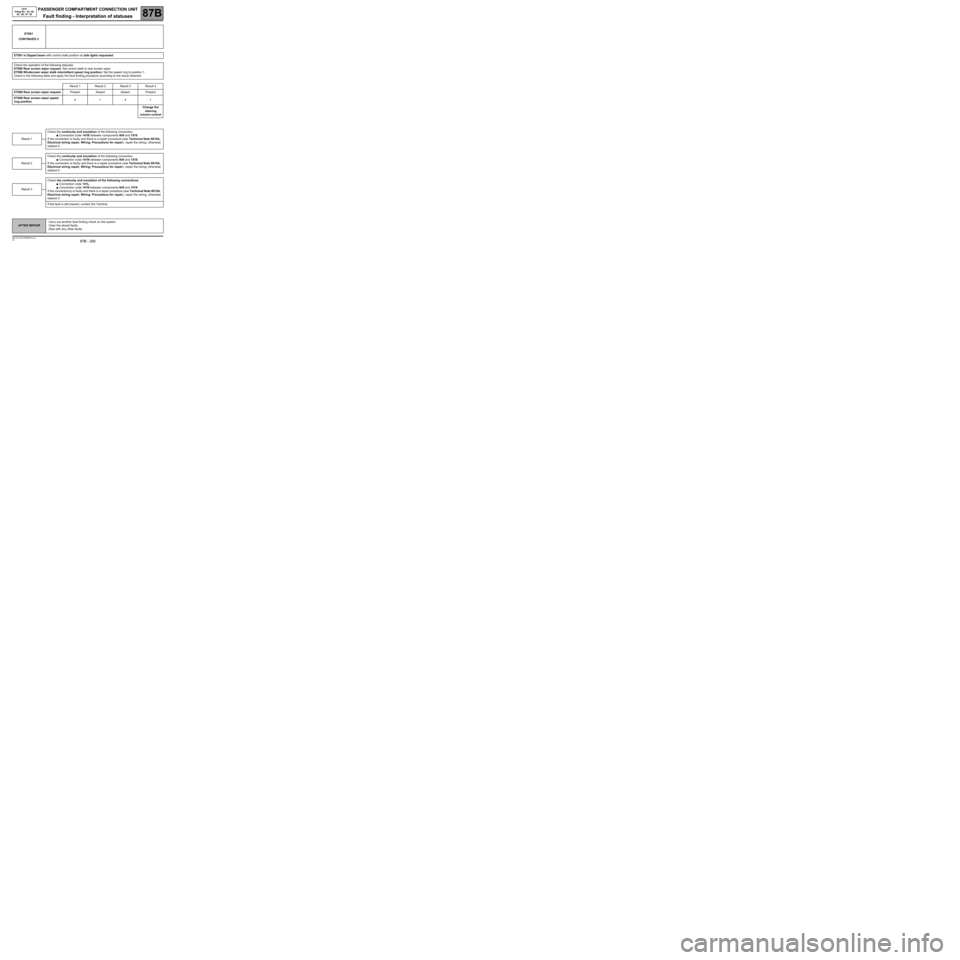
ET081
CONTINUED 2
ET081 is Dipped beam with control stalk position at side lights requested.
Check the operation of the following statuses:
ET080 Rear screen wiper request: Set control stalk to rear screen wiper.
ET096 Windscreen wiper stalk intermittent speed ring position: Set the speed ring to position 1.
Check in the following table and apply the fault finding procedure according to the result obtained.
Result 1 Result 2 Result 3 Result 4
ET080 Rear screen wiper requestPresent Absent Absent Present
ET096 Rear screen wiper speed
ring position4141
Change the
steering
column control
Check the continuity and insulation of the following connection:
●Connection code 141B between components 645 and 1519.
If the connection is faulty and there is a repair procedure (see Technical Note 6015A,
Electrical wiring repair, Wiring: Precautions for repair), repair the wiring, otherwise
replace it.
Check the continuity and insulation of the following connection:
●Connection code 141N between components 645 and 1519.
If the connection is faulty and there is a repair procedure (see Technical Note 6015A,
Electrical wiring repair, Wiring: Precautions for repair), repair the wiring, otherwise
replace it.
Check the continuity and insulation of the following connections:
●Connection code 141L.
●Connection code 141N between components 645 and 1519.
If the connection(s) is faulty and there is a repair procedure (see Technical Note 6015A,
Electrical wiring repair, Wiring: Precautions for repair), repair the wiring, otherwise
replace it.
If the fault is still present, contact the Techline.
Result 1
Result 2
Result 3
AFTER REPAIRCarry out another fault finding check on the system.
Clear the stored faults.
Deal with any other faults.
Page 201 of 391
PASSENGER COMPARTMENT CONNECTION UNIT
Fault finding - Interpretation of statuses87B
87B - 201
PASSENGER COMPARTMENT CONNECTION UNIT
Fault finding - Interpretation of statuses87B
87B - 201V9 MR-372-J84-87B000$516.mif
UCH
Vdiag No.: 44, 48,
4C, 4D, 4F, 50
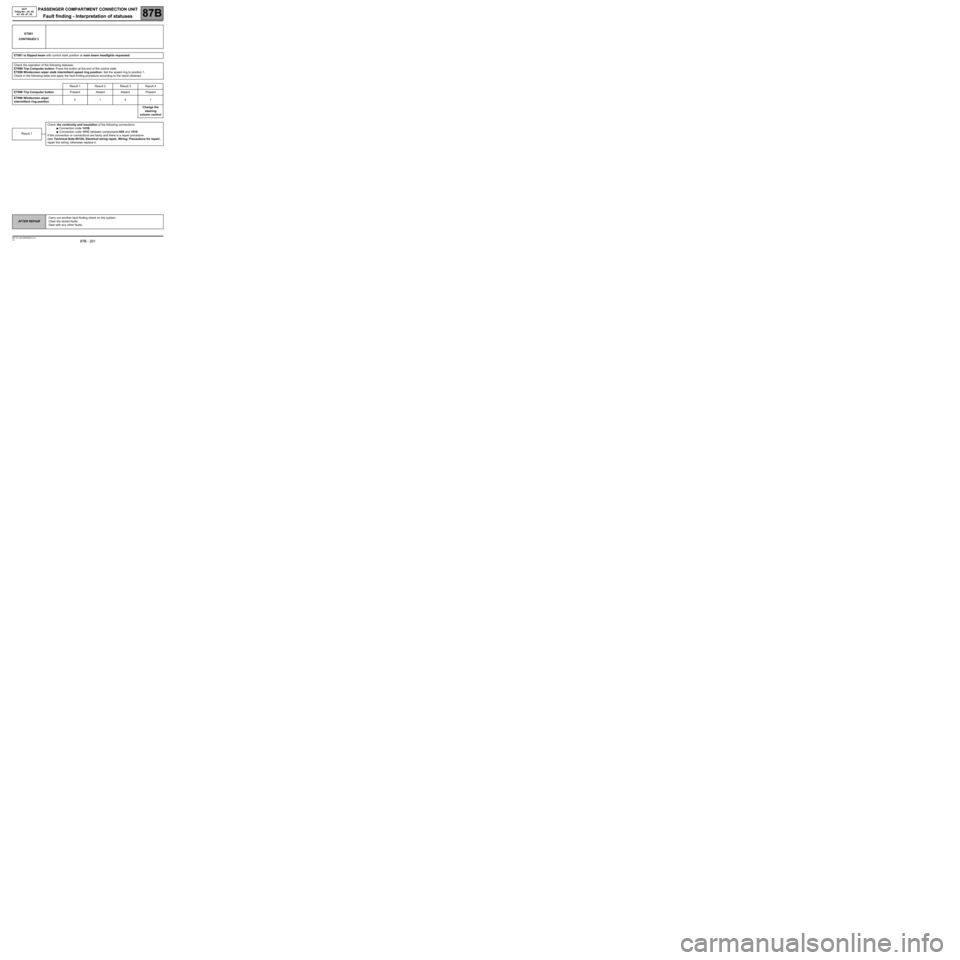
ET081
CONTINUED 3
ET081 is Dipped beam with control stalk position at main beam headlights requested.
Check the operation of the following statuses:
ET098 Trip Computer button: Press the button at the end of the control stalk.
ET096 Windscreen wiper stalk intermittent speed ring position: Set the speed ring to position 1.
Check in the following table and apply the fault finding procedure according to the result obtained.
Result 1 Result 2 Result 3 Result 4
ET098 Trip Computer buttonPresent Absent Absent Present
ET096 Windscreen wiper
intermittent ring position4141
Change the
steering
column control
Check the continuity and insulation of the following connections:
●Connection code 141B.
●Connection code 141C between components 645 and 1519.
If the connection or connections are faulty and there is a repair procedure
(see Technical Note 6015A, Electrical wiring repair, Wiring: Precautions for repair),
repair the wiring, otherwise replace it.Result 1
AFTER REPAIRCarry out another fault finding check on the system.
Clear the stored faults.
Deal with any other faults.
Page 203 of 391
PASSENGER COMPARTMENT CONNECTION UNIT
Fault finding - Interpretation of statuses87B
87B - 203
PASSENGER COMPARTMENT CONNECTION UNIT
Fault finding - Interpretation of statuses87B
87B - 203V9 MR-372-J84-87B000$516.mif
UCH
Vdiag No.: 44, 48,
4C, 4D, 4F, 50
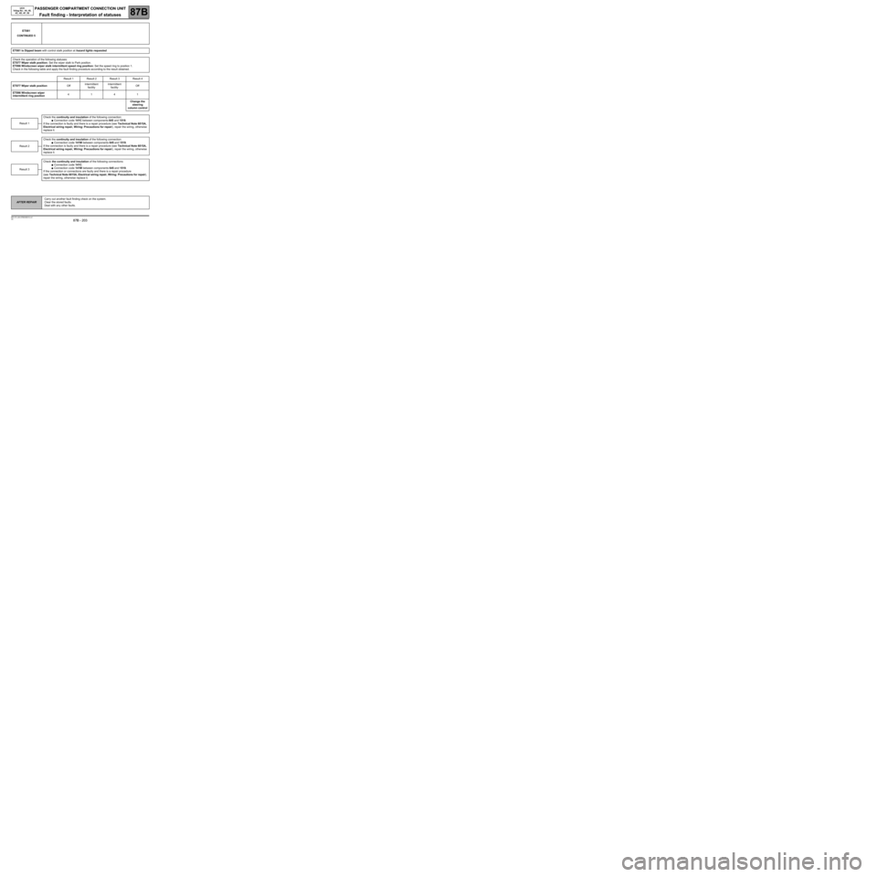
ET081
CONTINUED 5
ET081 is Dipped beam with control stalk position at hazard lights requested.
Check the operation of the following statuses:
ET077 Wiper stalk position: Set the wiper stalk to Park position.
ET096 Windscreen wiper stalk intermittent speed ring position: Set the speed ring to position 1.
Check in the following table and apply the fault finding procedure according to the result obtained.
Result 1 Result 2 Result 3 Result 4
ET077 Wiper stalk positionOffIntermittent
facilityIntermittent
facilityOff
ET096 Windscreen wiper
intermittent ring position4141
Change the
steering
column control
Check the continuity and insulation of the following connection:
●Connection code 141C between components 645 and 1519.
If the connection is faulty and there is a repair procedure (see Technical Note 6015A,
Electrical wiring repair, Wiring: Precautions for repair), repair the wiring, otherwise
replace it.
Check the continuity and insulation of the following connection:
●Connection code 141M between components 645 and 1519.
If the connection is faulty and there is a repair procedure (see Technical Note 6015A,
Electrical wiring repair, Wiring: Precautions for repair), repair the wiring, otherwise
replace it.
Check the continuity and insulation of the following connections:
●Connection code 141C.
●Connection code 141M between components 645 and 1519.
If the connection or connections are faulty and there is a repair procedure
(see Technical Note 6015A, Electrical wiring repair, Wiring: Precautions for repair),
repair the wiring, otherwise replace it.
Result 1
Result 2
Result 3
AFTER REPAIRCarry out another fault finding check on the system.
Clear the stored faults.
Deal with any other faults.
Page 219 of 391
PASSENGER COMPARTMENT CONNECTION UNIT
Fault finding - Interpretation of statuses87B
87B - 219
PASSENGER COMPARTMENT CONNECTION UNIT
Fault finding - Interpretation of statuses87B
87B - 219V9 MR-372-J84-87B000$559.mif
UCH
Vdiag No.: 44, 48,
4C, 4D, 4F, 50
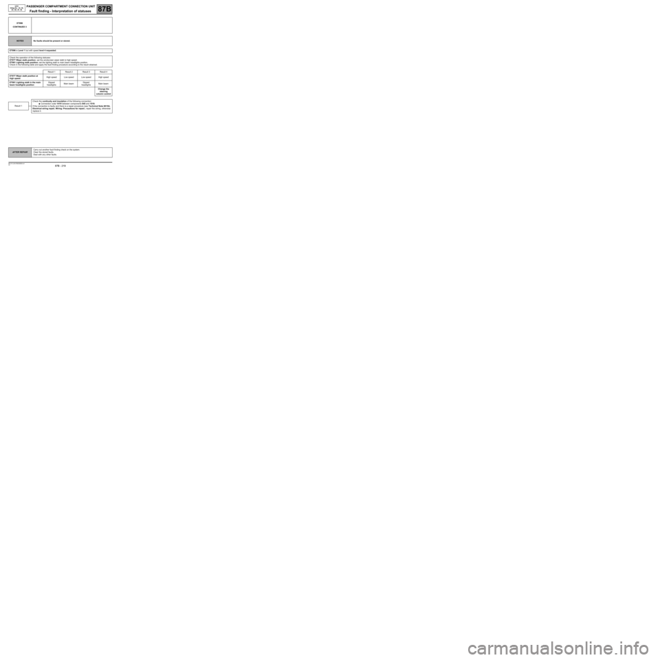
ET096
CONTINUED 3
NOTESNo faults should be present or stored.
ET096 is Level 1 but with speed level 4 requested.
Check the operation of the following statuses:
ET077 Wiper stalk position: set the windscreen wiper stalk to high speed.
ET081 Lighting stalk position: set the lighting stalk to main beam headlights position.
Check in the following table and apply the fault finding procedure according to the result obtained.
Result 1 Result 2 Result 3 Result 4
ET077 Wiper stalk position at
high speedHigh speed Low speed Low speed High speed
ET081 Lighting stalk in the main
beam headlights position Dipped
headlightsMain beamDipped
headlightsMain beam
Change the
steering
column control
Check the continuity and insulation of the following connection:
●Connection code 141H between components 645 and 1519.
If the connection is faulty and there is a repair procedure (see Technical Note 6015A,
Electrical wiring repair, Wiring: Precautions for repair), repair the wiring, otherwise
replace it.
Result 1
AFTER REPAIRCarry out another fault finding check on the system.
Clear the stored faults.
Deal with any other faults.