display RENAULT SCENIC 2009 J84 / 2.G Engine And Peripherals EDC16 Owner's Manual
[x] Cancel search | Manufacturer: RENAULT, Model Year: 2009, Model line: SCENIC, Model: RENAULT SCENIC 2009 J84 / 2.GPages: 273
Page 85 of 273
DIESEL INJECTION
Fault finding – Interpretation of faults13B
13B-85V3 MR-372-J84-13B250$360.mif
EDC16
PROGRAM No.: C1
Vdiag No.: 51
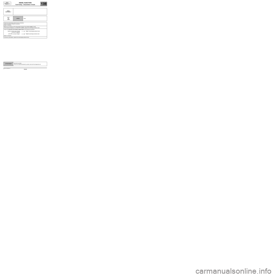
DF054
CONTINUED 1
CC.0
CO
3.DEF
NOTESNone
Check the turbocharging solenoid valve connections.
Check the injection computer connections.
Repair if necessary.
Measure the resistance of the turbocharging solenoid valve between tracks 1 and 2:
If the resistance displayed is not 15.4 ± 0.7 Ω at 20˚C, replace the turbocharger solenoid valve.
Check the continuity and insulation against earth of the following connections:
Injection computer grey 32-track
connector C, track E1Track 1 turbocharging solenoid valve
UPC PPM1 connector Track 1 Track 2 turbocharger solenoid valve
Repair if necessary.
If the fault is still present, replace the turbocharging solenoid valve.
AFTER REPAIRDeal with any faults.
Carry out a road test followed by another check with the diagnostic tool.
Page 86 of 273
DIESEL INJECTION
Fault finding – Interpretation of faults13B
13B-86V3 MR-372-J84-13B250$360.mif
EDC16
PROGRAM No.: C1
Vdiag No.: 51
*Opening cyclic ratioDF054
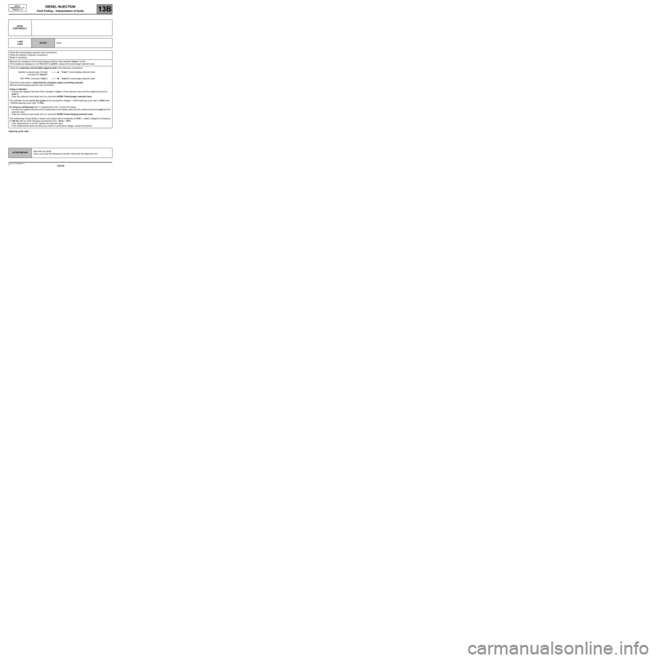
CONTINUED 2
1.DEF
2.DEF
NOTESNone
Check the turbocharging solenoid valve connections.
Check the injection computer connections.
Repair if necessary.
Measure the resistance of the turbocharging solenoid valve between tracks 1 and 2:
If the resistance displayed is not 15.4 ± 0.7 Ω at 20˚C, replace the turbocharger solenoid valve.
Check the continuity and insulation against earth of the following connections:
Injection computer grey 32-track
connector C, track E1Track 1 turbocharging solenoid valve
UPC PPM1 connector Track 1 Track 2 Turbocharger solenoid valve
If the fault is still present, check that the computer output is working correctly.
With the turbocharging solenoid valve connected:
Using a voltmeter:
–Connect the negative terminal of the voltmeter to track 1 of the solenoid valve and the negative terminal to
track 2.
–Clear any solenoid valve faults and run command AC004 Turbocharger solenoid valve.
The voltmeter should display ten cycles of two successive voltages: ~ 2.5 V (opening cyclic ratio* of 20%) then
~ 8.75 V (opening cyclic ratio* of 70%).
Or using an oscilloscope (at 5 V range/division and 1 ms/div time base):
–Connect the negative terminal of the oscilloscope to the battery earth and the positive terminal to track 2 of the
solenoid valve.
–Clear any solenoid valve faults and run command AC004 Turbocharging solenoid valve.
The oscilloscope should display a square wave signal with an amplitude of 12.5V (~ battery voltage) at a frequency
of 140 Hz (with an OCR changing successively from ~ 20 to ~ 70%).
–if the measurement is correct, replace the solenoid valve.
–if the measurement does not show any control or continuous voltage, contact the techline.
AFTER REPAIRDeal with any faults.
Carry out a road test followed by another check with the diagnostic tool.
Page 101 of 273
DIESEL INJECTION
Fault finding – Interpretation of faults13B
13B -101V3 MR-372-J84-13B250$405.mif
EDC16
PROGRAM No.: C1
Vdiag No.: 51
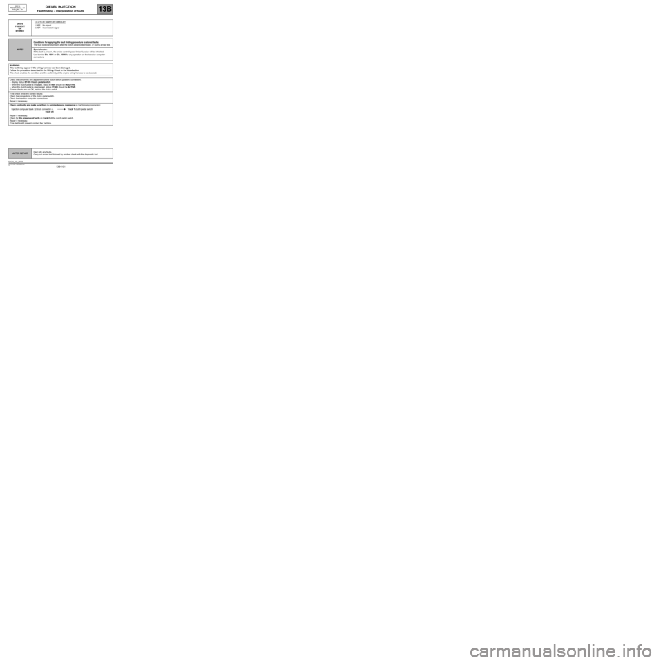
DF070
PRESENT
OR
STOREDCLUTCH SWITCH CIRCUIT
1.DEF : No signal
2.DEF : Inconsistent signal
NOTESConditions for applying the fault finding procedure to stored faults:
The fault is declared present after the clutch pedal is depressed, or during a road test.
Special notes:
If this fault is present, the cruise control/speed limiter function will be inhibited.
Use bornier Ele. 1681 or Ele. 1590 for any operation on the injection computer
connectors.
WARNING
This fault may appear if the wiring harness has been damaged.
Follow the procedure described in the Wiring Check in the Introduction.
This check enables the condition and the conformity of the engine wiring harness to be checked.
Check the conformity and adjustment of the clutch switch (position, connection).
–display status ET405 Clutch pedal switch:
–when the clutch pedal is engaged, status ET405 should be INACTIVE,
–when the clutch pedal is disengaged, status ET405 should be ACTIVE.
If these checks are not OK, replace the clutch switch.
If the check show the correct results:
Check the connections of the clutch pedal switch.
Check the injection computer connections.
Repair if necessary.
Check continuity and make sure there is no interference resistance on the following connection:
Injection computer black 32-track connector A,
track C4Track 1 clutch pedal switch
Repair if necessary.
Check for the presence of earth on track 2 of the clutch pedal switch.
Repair if necessary.
If the fault is still present, contact the Techline.
AFTER REPAIRDeal with any faults.
Carry out a road test followed by another check with the diagnostic tool.
EDC16_V51_DF070
Page 106 of 273
DIESEL INJECTION
Fault finding – Interpretation of faults13B
13B -106V3 MR-372-J84-13B250$405.mif
EDC16
PROGRAM No.: C1
Vdiag No.: 51
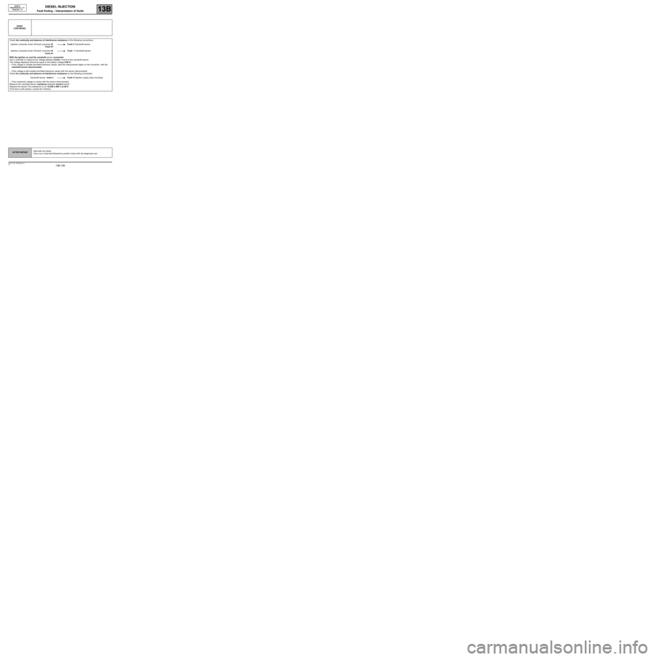
DF097
CONTINUED
Check the continuity and absence of interference resistance of the following connections:
Injection computer brown 48-track connector B,
Track D1Track 2 Camshaft sensor
Injection computer brown 48-track connector B,
Track A1Track 1 Camshaft sensor
With the ignition on and the camshaft sensor connected:
Use a voltmeter to measure the voltage between tracks 1 and 3 of the camshaft sensor:
The voltage displayed should be equal to the battery voltage 0.08 V)
–If the voltage is outside permitted tolerance values, take the measurement again on the connector, with the
camshaft sensor disconnected,
–If the voltage is still outside permitted tolerance values with the sensor disconnected.
Check for continuity and absence of interference resistance on the following connection:
Camshaft sensor, track 3 Track 5 injection supply relay mounting
–If the measured voltage is correct with the sensor disconnected.
Measure the camshaft sensor resistance between tracks 2 and 3.
Replace the sensor if its resistance is not 10,250 ± 500 Ω at 20˚C
If the fault is still present, contact the Techline.
AFTER REPAIRDeal with any faults.
Carry out a road test followed by another check with the diagnostic tool.
Page 109 of 273
DIESEL INJECTION
Fault finding – Interpretation of faults13B
13B -109V3 MR-372-J84-13B250$405.mif
EDC16
PROGRAM No.: C1
Vdiag No.: 51
DF195
CONTINUED
With the ignition on and the camshaft sensor connected:
Use a voltmeter to measure the voltage between tracks 1 and 3 of the camshaft sensor:
The voltage displayed should be equal to the battery voltage 0.08 V)
–If the voltage is outside permitted tolerance values, take the measurement again on the connector, with the
camshaft sensor disconnected,
–If the voltage is still outside permitted tolerance values with the sensor disconnected.
Check for continuity and absence of interference resistance on the following connection:
Camshaft sensor, track 3 + after ignition feed after relay
–If the measured voltage is correct with the sensor disconnected,
Measure the resistance of the camshaft sensor between tracks 2 and 3.
Replace the sensor if its resistance is not 10,250 ± 500 Ω at 20˚C
Check that the engine speed sensor is correctly mounted and that the flywheel target is not damaged.
Check that the gap between the engine speed sensor and the flywheel is 0.5 to 1.8 mm.
Measure the resistance of the engine speed sensor between terminals A and B of its black connector.
If the winding resistance is not between 510 Ω and 850 Ω at an engine temperature of 20˚C, replace the engine
speed sensor.
AFTER REPAIRDeal with any faults.
Carry out a road test followed by another check with the diagnostic tool.
Page 112 of 273
DIESEL INJECTION
Fault finding – Interpretation of faults13B
13B-112V3 MR-372-J84-13B250$405.mif
EDC16
PROGRAM No.: C1
Vdiag No.: 51
DF209
CONTINUED 2
CC.1
1.DEF
NOTESNone.
Check the EGR valve connections.
Check the injection computer connections.
Repair if necessary.
Check for continuity and insulation to + 12 V on the following connections:
Injection computer brown 48-track connector B, track J2 Track 6 EGR valve.
Injection computer 32-track grey connector C track C2 Track 4 EGR valve
Injection computer brown 48-track connector B, track F4 Track 2 EGR valve
If the connection or connections are faulty and there is a repair method (see Technical Note 6015A, Repairing
electrical wiring, Wiring: Precautions for repair), repair the wiring, otherwise replace it.
Ensure the presence of + 5 V on track 2 of the EGR valve.
EGR valve with a square connector:
Measure the resistance of the EGR valve position feedback potentiometer between tracks 2 and 4.
If the resistance displayed is not between 3.9 k
Ω < X < 9.1 kΩ at 20˚C, replace the EGR valve.
EGR valve with a flat connector:
Replace the EGR valve.
If the valve is jammed or irrevocably seized, replace the EGR valve.
When replacing the EGR valve, run command SC036 Reinitialise programming and select EGR valve to
reinitialise the EGR valve offsets (see Replacement of components).
AFTER REPAIRDeal with any faults.
Carry out a road test followed by another check with the diagnostic tool.
Page 116 of 273
DIESEL INJECTION
Fault finding – Interpretation of faults13B
13B-116V3 MR-372-J84-13B250$405.mif
EDC16
PROGRAM No.: C1
Vdiag No.: 51
DF226
CONTINUED 3
1.DEF
to 3.DEF
NOTESAfter any work is carried out on the damper valve, run SC036
Reinitialise programming and select Damper valve, then
switch off the ignition and wait 1 minute.
Check the damper valve connections.
Check the injection computer connections.
Repair if necessary.
Check the continuity, insulation and absence of interference resistance of the following connections:
Earth Track 1 of the damper valve
Injection supply relay mounting, Track 5 Track 2 of the damper valve
Injection computer brown 48-track connector B, track J4 Track 3 of the damper valve
Injection computer brown 48-track connector B, track B2 Track 4 of the damper valve
Repair if necessary.
If the fault is still present, check that the computer output is working correctly.
Damper valve connected:
–connect the negative terminal of the voltmeter to track 1 of the damper valve,
–connect the positive terminal of the voltmeter to track 3 of the damper valve,
–use command AC012 Damper valve:
The voltmeter should display ten cycles of two successive voltages: ~ 2.5 V (OCR of 20%) then ~ 8.75 V (OCR
of 70%).
If the voltmeter does not indicate any control while the command is running (ten 1-second cycles), contact the
Techline.
AFTER REPAIRDeal with any faults.
Carry out a road test followed by another check with the diagnostic tool.
Page 118 of 273
DIESEL INJECTION
Fault finding – Interpretation of faults13B
13B-118V3 MR-372-J84-13B250$405.mif
EDC16
PROGRAM No.: C1
Vdiag No.: 51
DF272
PRESENT
OR
STOREDEGR VALVE CONTROL CIRCUIT
1.DEF : Valve jammed open
2.DEF : Valve jammed closed
NOTESConditions for applying the fault finding procedure to stored faults:
The fault is declared present after a road test.
Special notes:
The EGR function is deactivated if several faults with DF226 Damper valve circuit are
present.
If 1.DEF is present,
–the level 1 warning light is lit,
–the vehicle performance is reduced,
–there is smoke coming from the exhaust.
Use bornier Ele. 1681 or Ele. 1590 for any operation on the injection computer
connectors.
Check the EGR valve connections.
Check the injection computer connections.
Repair if necessary.
Check the continuity and the absence of interference resistance on the following connections:
Injection computer brown 48-track connector B, track C2 Track 1 EGR valve connector
Injection computer brown 48-track connector B, track D2 Track 5 EGR valve connector
If the connection or connections are faulty and there is a repair method (see Technical Note 6015A, Repairing
electrical wiring, Wiring: Precautions for repair), repair the wiring, otherwise replace it.
Check that there are no leaks on the EGR circuit (pipes pierced or damaged) and that the clamps are properly
tightened.
Measure the resistance of the EGR valve motor between tracks 1 and 5.
If the resistance displayed is not between 1
Ω < X < 400Ω at 20˚C, replace the EGR valve.
If the valve is jammed or irrevocably seized, replace the EGR valve.
Run command SC036 Reset programming and select EGR valve to reset the EGR valve offsets (see
Replacement of components).
AFTER REPAIRDeal with any faults.
Carry out a road test followed by another check with the diagnostic tool.
EDC16_V51_DF272
Page 133 of 273
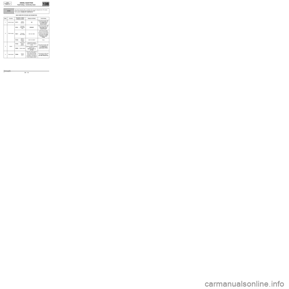
DIESEL INJECTION
Fault finding – Conformity check13B
13B - 133V3 MR-372-J84-13B250$450.mif
EDC16
PROGRAM NO.: C1
Vdiag No.: 51DIESEL INJECTION
Fault finding – Conformity check
MAIN COMPUTER STATUSES AND PARAMETERS
NOTESOnly check conformity after a complete check using the diagnostic tool. The values
shown in this conformity check are given as a guide.
Test conditions: ENGINE OFF, IGNITION ON.
Order FunctionParameter or Status
checked or ActionDisplay and Notes Fault finding
1Vehicle impactET077:Impact
detectedNOIn the event of a fault, refer
to the interpretation of
fault DF069 Impact
detected signal.
2Power supplyET001:Computer
+ after ignition
feedPRESENTIn the event of a fault, refer
to the interpretation of
DF015 Main relay
control circuit.
PR071:Computer
feed voltage9 V < X < 16 VIn the event of a fault,
carry out a fault finding
procedure on the charging
circuit and refer to the
interpretation for DF047
Computer supply
voltage.
PR358:Sensor
reference
voltage3.4 V < X <3.8 VNone
3SpeedPR190:Engine idle
speed
setpoint.Indicates the engine's
rotational speed setpoint
in rpm.In the event of a fault, refer
to the interpretation for
fault DF005 Engine
speed sensor circuit.
PR055:Engine speedGives the engine's rotational
speed in rpm.
With the ignition on
at 0 rpm
4Speed signalPR089:Vehicle
speedGives the vehicle speed in
mph. This parameter is
transmitted by the ABS
computer. This signal is
transmitted to the injection
on the multiplex network.In the event of a fault, test
the multiplex network.
(See 88B, Multiplexing).
EDC16_V51_CCONF
MR-372-J84-13B250$450.mif
Page 134 of 273
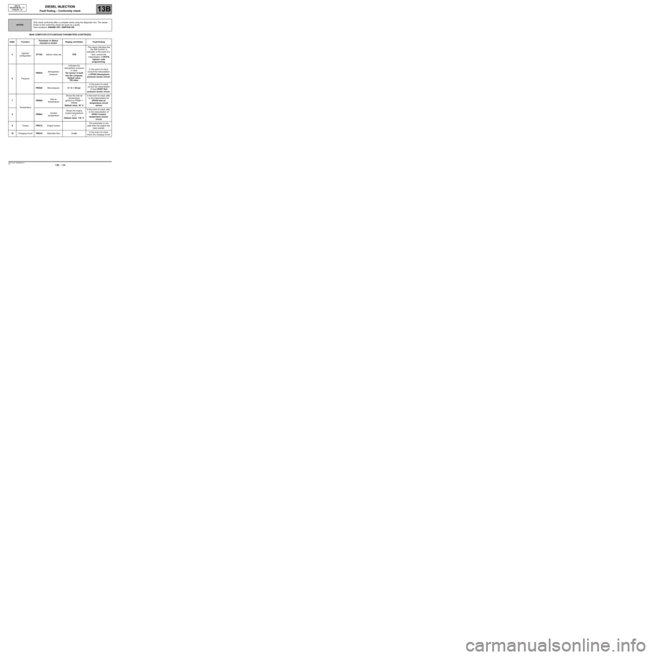
DIESEL INJECTION
Fault finding – Conformity check13B
13B - 134V3 MR-372-J84-13B250$450.mif
EDC16
PROGRAM NO.: C1
Vdiag No.: 51
MAIN COMPUTER STATUSES AND PARAMETERS (CONTINUED)
NOTESOnly check conformity after a complete check using the diagnostic tool. The values
shown in this conformity check are given as a guide.
Test conditions: ENGINE OFF, IGNITION ON.
Order FunctionParameter or Status
checked or ActionDisplay and Notes Fault finding
5Injection
configurationET104:Injector code useYESThis status indicates that
the IMA function is
activated. In the event of a
fault, consult the
interpretation of DF276
Injector code
programming.
6PressurePR035:Atmospheric
pressureIndicates the
atmospheric pressure
in mbar.
The sensor is built
into the computer.
Default value:
750 mbar.In the event of a fault,
consult the interpretation
of DF003 Atmospheric
pressure sensor circuit.
PR038:Rail pressure0 < X < 30 barIn the event of a fault,
consult the interpretation
of fault DF007 Rail
pressure sensor circuit.
7
TemperaturePR059:Inlet air
temperatureShows the inlet air
temperature
Ignition on PR061 =
PR059
Default value: 20 ˚CIn the event of a fault, refer
to the interpretation for
DF039 Inlet air
temperature circuit
sensor
8PR064:Coolant
temperatureShows the engine
coolant temperature
in ˚C
Default value: 119 ˚CIn the event of a fault, refer
to the interpretation of
DF001 Coolant
temperature sensor
circuit.
9TorquePR015:Engine torqueThis parameter is only
valid when the engine has
been started.
10Charging circuitPR016:Alternator flow0 mAIn the event of a fault,
check the charging circuit.