display RENAULT SCENIC 2009 J84 / 2.G Engine And Peripherals EDC16 Owner's Guide
[x] Cancel search | Manufacturer: RENAULT, Model Year: 2009, Model line: SCENIC, Model: RENAULT SCENIC 2009 J84 / 2.GPages: 273
Page 135 of 273
DIESEL INJECTION
Fault finding – Conformity check13B
13B - 135V3 MR-372-J84-13B250$450.mif
EDC16
PROGRAM NO.: C1
Vdiag No.: 51
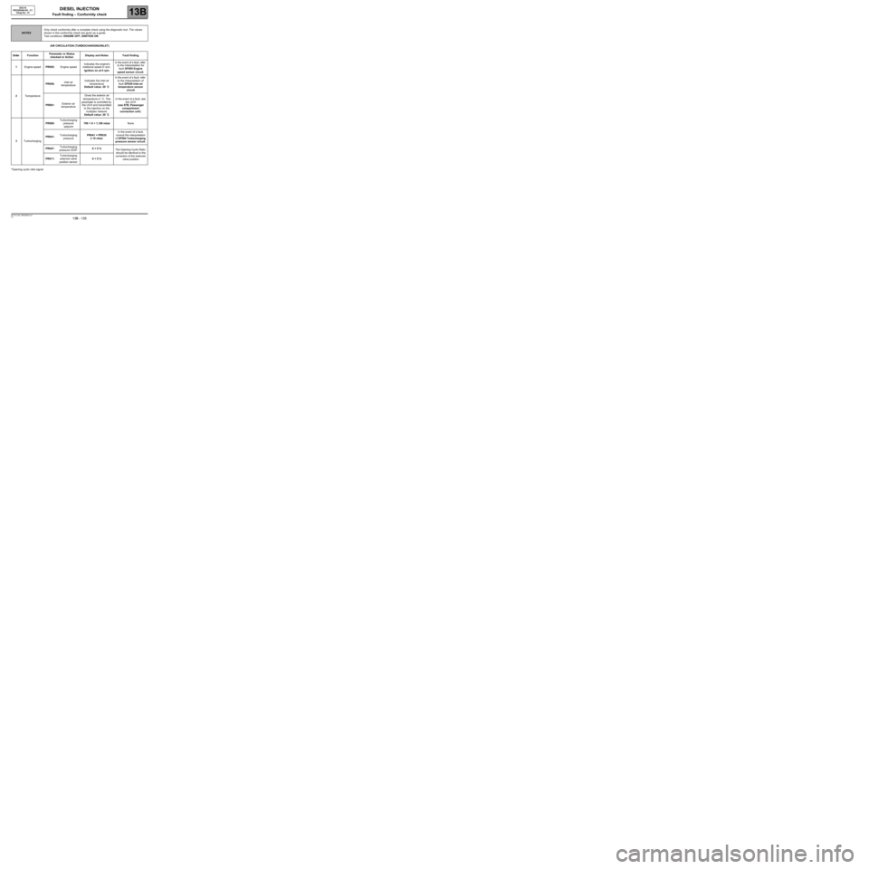
AIR CIRCULATION (TURBOCHARGING/INLET)
*Opening cyclic ratio signal
NOTESOnly check conformity after a complete check using the diagnostic tool. The values
shown in this conformity check are given as a guide.
Test conditions: ENGINE OFF, IGNITION ON.
Order FunctionParameter or Status
checked or ActionDisplay and Notes Fault finding
1Engine speedPR055:Engine speedIndicates the engine's
rotational speed in rpm.
Ignition on at 0 rpmIn the event of a fault, refer
to the interpretation for
fault DF005 Engine
speed sensor circuit.
2TemperaturePR059:Inlet air
temperatureIndicates the inlet air
temperature
Default value: 20 ˚CIn the event of a fault, refer
to the interpretation of
fault DF039 Inlet air
temperature sensor
circuit
PR061:Exterior air
temperatureGives the exterior air
temperature in ˚C. This
parameter is controlled by
the UCH and transmitted
to the injection on the
multiplex network.
Default value: 20 ˚CIn the event of a fault, see
the UCH
(see 87B, Passenger
compartment
connection unit).
3TurbochargingPR009:Turbocharging
pressure
setpoint790 < X < 1,190 mbarNone
PR041:Turbocharging
pressurePR041 = PR035
± 10 mbarIn the event of a fault,
consult the interpretation
of DF004 Turbocharging
pressure sensor circuit.
PR047:Turbocharging
pressure OCR*X < 5 %
The Opening Cyclic Ratio
should be identical to the
correction of the solenoid
valve position PR011:Turbocharging
solenoid valve
position sensorX < 5 %
Page 136 of 273
DIESEL INJECTION
Fault finding – Conformity check13B
13B - 136V3 MR-372-J84-13B250$450.mif
EDC16
PROGRAM NO.: C1
Vdiag No.: 51
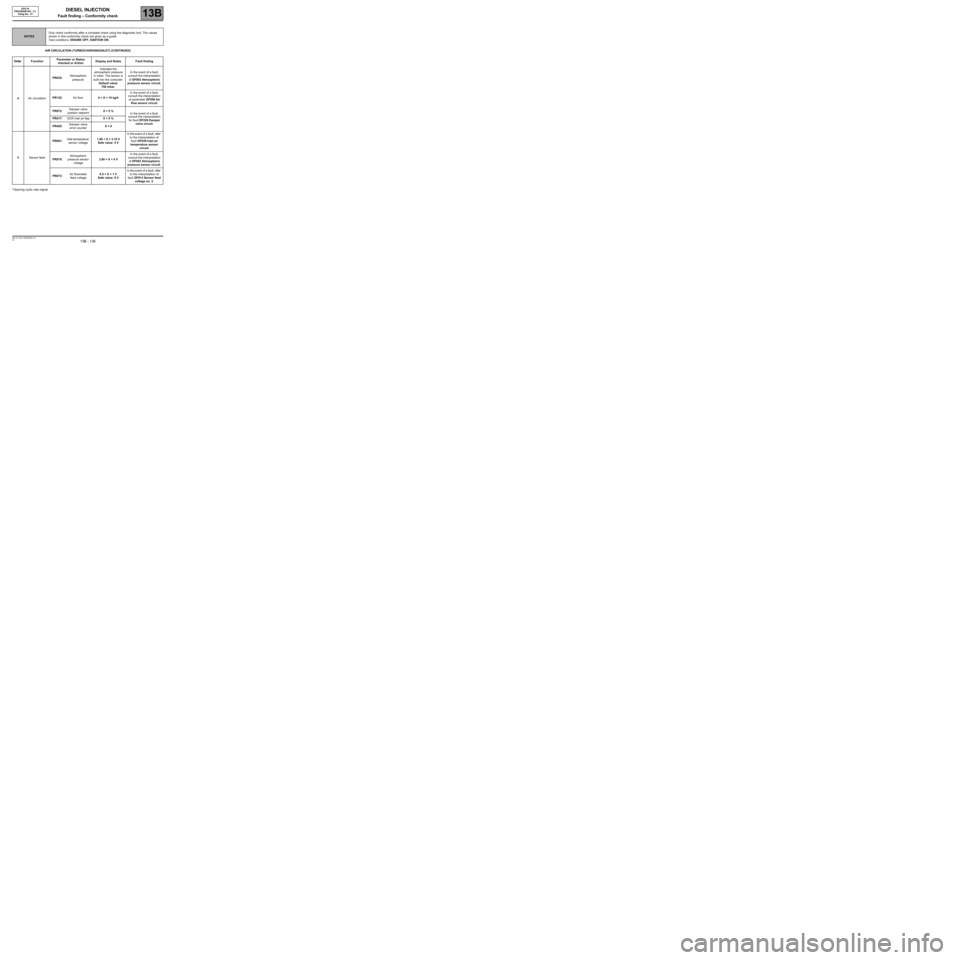
AIR CIRCULATION (TURBOCHARGING/INLET) (CONTINUED)
*Opening cyclic ratio signal
NOTESOnly check conformity after a complete check using the diagnostic tool. The values
shown in this conformity check are given as a guide.
Test conditions: ENGINE OFF, IGNITION ON.
Order FunctionParameter or Status
checked or ActionDisplay and Notes Fault finding
4Air circulationPR035:Atmospheric
pressureIndicates the
atmospheric pressure
in mbar. The sensor is
built into the computer.
Default value:
750 mbar.In the event of a fault,
consult the interpretation
of DF003 Atmospheric
pressure sensor circuit.
PR132:Air flow0 < X < 10 kg/hIn the event of a fault,
consult the interpretation
of parameter DF056 Air
flow sensor circuit.
PR672:Damper valve
position setpointX < 5 %
In the event of a fault,
consult the interpretation
for fault DF226 Damper
valve circuit. PR417:OCR inlet air flapX < 5 %
PR420:Damper valve
error counterX = 0
5Sensor feedPR081:Inlet temperature
sensor voltage1.90 < X < 3.10 V
Safe value: 5 VIn the event of a fault, refer
to the interpretation of
fault DF039 Inlet air
temperature sensor
circuit.
PR079:Atmospheric
pressure sensor
voltage3.80 < X < 4 VIn the event of a fault,
consult the interpretation
of DF003 Atmospheric
pressure sensor circuit.
PR073:Air flowmeter
feed voltage0.5 < X < 1 V
Safe value: 0 VIn the event of a fault, refer
to the interpretation of
fault DF013 Sensor feed
voltage no. 3.
Page 137 of 273
DIESEL INJECTION
Fault finding – Conformity check13B
13B - 137V3 MR-372-J84-13B250$450.mif
EDC16
PROGRAM NO.: C1
Vdiag No.: 51
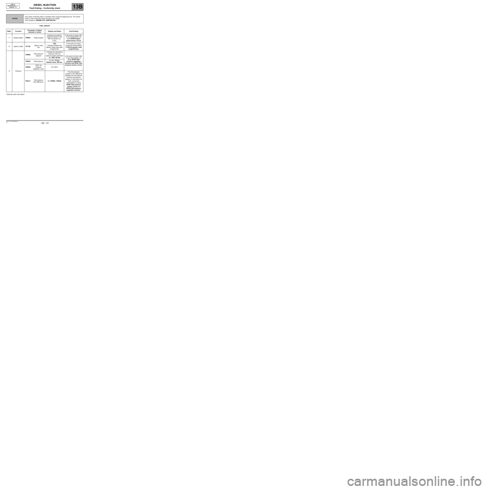
FUEL CIRCUIT
*Opening cyclic ratio signal
NOTESOnly check conformity after a complete check using the diagnostic tool. The values
shown in this conformity check are given as a guide.
Test conditions: ENGINE OFF, IGNITION ON.
Order FunctionParameter or Status
checked or ActionDisplay and Notes Fault finding
1Engine speedPR055:Engine speedIndicates the engine's
rotational speed in rpm.
With the ignition on,
0 rpm.In the event of a fault, refer
to the interpretation for
fault DF005 Engine
speed sensor circuit.
2Injector codesET104:Injector code
useYES
Indicates whether the
injector codes have been
programmedIn the event of a fault,
consult the interpretation
of DF276 Injector code
programming.
3PressurePR008:Rail pressure
setpointIndicates the theoretical
pressure value for
optimum engine operation
X = 250 ± 50 barIn the event of a fault, refer
to the interpretation of
faults DF053 Rail
pressure regulation
function and DF007 Rail
pressure sensor circuit. PR038:Rail pressure0 < X < 10 bar
Default value: 250 bar.
PR048:OCR* rail
pressure
regulation valveX = 15 %
PR213:Rail pressure
loop differenceX = PR008 - PR038The fuel pressure
variation is the difference
between the rail pressure
and the rail pressure
setpoint. In the event of a
fault, consult the
interpretation of faults
DF007 Rail pressure
sensor circuit and
DF053 Rail pressure
regulation function.
Page 138 of 273
DIESEL INJECTION
Fault finding – Conformity check13B
13B - 138V3 MR-372-J84-13B250$450.mif
EDC16
PROGRAM NO.: C1
Vdiag No.: 51
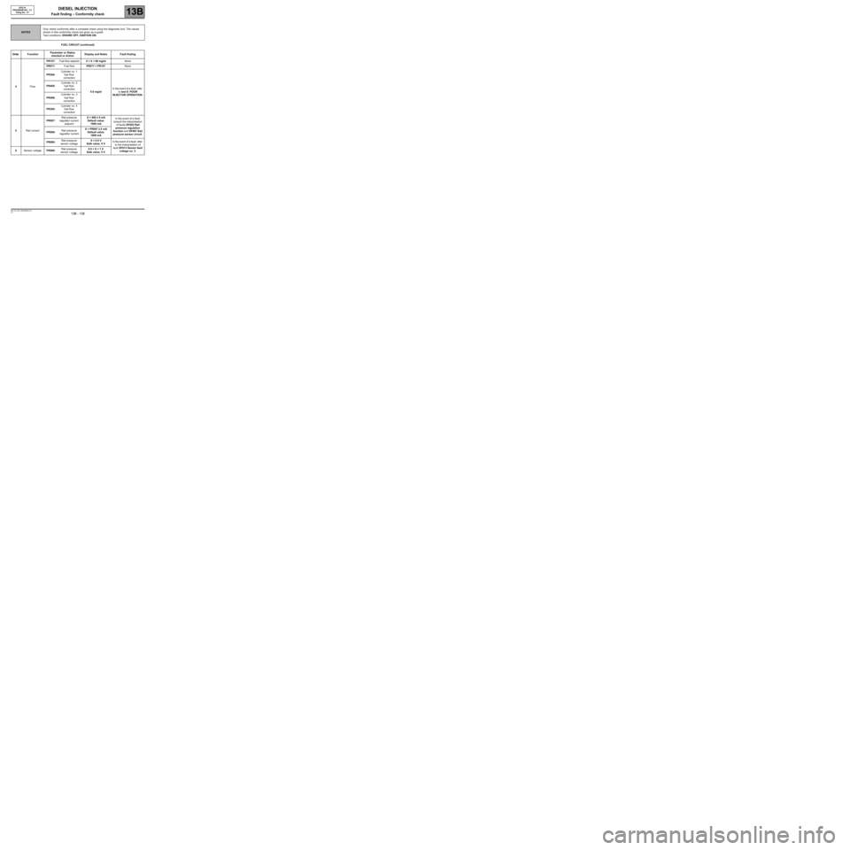
FUEL CIRCUIT (continued)
NOTESOnly check conformity after a complete check using the diagnostic tool. The values
shown in this conformity check are given as a guide.
Test conditions: ENGINE OFF, IGNITION ON.
Order FunctionParameter or Status
checked or ActionDisplay and Notes Fault finding
4FlowPR157:Fuel flow setpoint0 < X < 60 mg/stNone
PR017:Fuel flowPR017 = PR157None
PR364:Cylinder no. 1
fuel flow
correction
0.0 mg/stIn the event of a fault, refer
to test 8: POOR
INJECTOR OPERATION. PR405:Cylinder no. 2
fuel flow
correction
PR406:Cylinder no. 3
fuel flow
correction
PR365:Cylinder no. 4
fuel flow
correction
5Rail currentPR007:Rail pressure
regulator current
setpointX = 400 ± 5 mA
Default value:
1600 mAIn the event of a fault,
consult the interpretation
of faults DF053 Rail
pressure regulation
function and DF007 Rail
pressure sensor circuit. PR006:Rail pressure
regulator currentX = PR007 ± 5 mA
Default value:
1600 mA
PR080:Rail pressure
sensor voltageX = 0.5 V
Safe value: 5 VIn the event of a fault, refer
to the interpretation of
fault DF013 Sensor feed
voltage no. 3. 6Sensor voltagePR080:Rail pressure
sensor voltage0.5 < X < 1 V
Safe value: 5 V
Page 139 of 273
DIESEL INJECTION
Fault finding – Conformity check13B
13B - 139V3 MR-372-J84-13B250$450.mif
EDC16
PROGRAM NO.: C1
Vdiag No.: 51
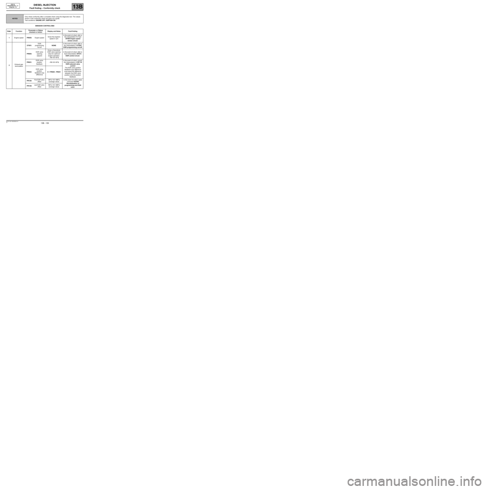
EMISSION CONTROL/OBD
NOTESOnly check conformity after a complete check using the diagnostic tool. The values
shown in this conformity check are given as a guide.
Test conditions: ENGINE OFF, IGNITION ON.
Order FunctionParameter or Status
checked or ActionDisplay and Notes Fault finding
1Engine speedPR055:Engine speedGives the engine's
speed in rpmIn the event of a fault, refer to
the interpretation for fault
DF005 Engine speed
sensor circuit.
2Exhaust gas
recirculationET651:EGR
programming
cut-offNONEIn the event of a fault, refer to
the interpretation of ET651
EGR programming cut-off.
PR005:EGR valve
opening
setpointGives a theoretical
EGR valve opening
value for optimum
engine operation.
- 10 < X < 0 %In the event of a fault, refer to
fault interpretation DF272
EGR control circuit.
PR051:EGR valve
position
feedback- 10 < X < 0 %In the event of a fault, consult
the interpretation of DF118
EGR solenoid valve
control
The EGR valve position
feedback loop difference
must equal the difference
between the EGR valve
position and the position
feedback. PR022:EGR valve
position
feedback loop
differenceX = PR005 - PR051
PR128:First EGR valve
offset10 % < X < 40 %
(average value)In the event of a fault, apply
command SC036
Reinitialisation of
programming and EGR
valve. PR129:Last EGR valve
offset10 % < X < 40 %
(average value)
Page 140 of 273
DIESEL INJECTION
Fault finding – Conformity check13B
13B - 140V3 MR-372-J84-13B250$450.mif
EDC16
PROGRAM NO.: C1
Vdiag No.: 51
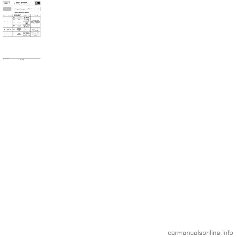
EMISSION CONTROL/OBD (CONTINUED)
NOTESOnly check conformity after a complete check using the diagnostic tool. The values
shown in this conformity check are given as a guide.
Test conditions: ENGINE OFF, IGNITION ON.
Order FunctionParameter or Status
checked or ActionDisplay and Notes Fault finding
3Air regulationPR171:Air flow setpoint
for the EGR750 ± 200 mg/st
In the event of a fault,
consult the interpretation of
parameter DF056 Air flow
sensor circuit. PR132:Air flow0 < X < 10 kg/h
PR146:Inlet air flowIndicates the air flow
entering the engine
in mg/st
0 mg/st
PR131:EGR air flow
variationX = PR146 - PR171
should be close to 0
with ignition on
4Sensor feedPR077:EGR valve
position sensor
voltage0.5 < X < 1.5 V
default value: 0 VIn the event of a fault, refer
to the interpretation of fault
DF012 Sensor supply
voltage no. 2.
5TemperaturePR064:Coolant
temperatureShows the engine
coolant temperature
in ˚C
Default value: 119 ˚CIn the event of a fault, refer
to the interpretation of
DF001 Coolant
temperature sensor
circuit.
Page 141 of 273
DIESEL INJECTION
Fault finding – Conformity check13B
13B - 141V3 MR-372-J84-13B250$450.mif
EDC16
PROGRAM NO.: C1
Vdiag No.: 51
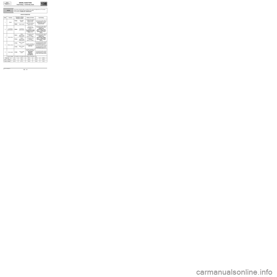
DRIVER PARAMETERS
NOTESOnly check conformity after a complete check using the diagnostic tool. The values
shown in this conformity check are given as a guide.
Test conditions: ENGINE OFF, IGNITION ON.
Order FunctionParameter or Status
checked or ActionDisplay and Notes Fault finding
1EnginePR190:Idle speed
setpointIndicates the engine's
rotational speed
setpoint in rpm.In the event of a fault, refer to
the interpretation for fault
DF005 Engine speed
sensor circuit.
PR055:Engine speedGives the engine's
speed in rpm
2Accelerator
pedal position *PR030:Accelerator
pedal positionIndicates the
accelerator pedal
position.
If no pressure is being
applied to the pedal
PR030 = 0 %In the event of a fault, refer to
the interpretation of fault
DF008 Pedal
potentiometer circuit
gang 1 or DF009 Pedal
potentiometer circuit
gang 2.
3Sensor feedPR147:Pedal
potentiometer
voltage gang 1Accelerator pedal
released
0.70 < X < 0.80 VIn the event of a fault, refer to
the interpretation of fault
DF008 Pedal
potentiometer voltage
track 1 or DF009 Pedal
potentiometer voltage
track 2. PR148:Pedal
potentiometer
voltage gang 2Accelerator pedal
released
0.35 < X < 0.40 V
4Brake contactET704:Brake contact
no. 1
Indicates recognition of
brake pedal contacts
INACTIVEIn the event of a fault, consult
the interpretation of status
ET704 Brake switch no. 1.
ET705:Brake contact
no. 2In the event of a fault, consult
the interpretation for status
ET705 Brake switch no. 2.
5Clutch pedalET405:Clutch pedal
switchIndicates recognition of
clutch pedal contacts
RELEASED
(MANUAL)
or WITHOUT
(AUTOMATIC)In the event of a fault, consult
the interpretation of status
ET405 Clutch pedal switch.
(*) Pedal voltages - cold, ignition on (average values stated for information only).
Pedal load 0 % 25 % 50 % 100 % 120 %
Gang 1 voltage 0.74 V 1.52 V 2.09 V 3.23 V 3.67 V
Gang 2 voltage 0.37 V 0.77 V 1.06 V 1.64 V 1.87 V
Page 142 of 273
DIESEL INJECTION
Fault finding – Conformity check13B
13B - 142V3 MR-372-J84-13B250$450.mif
EDC16
PROGRAM NO.: C1
Vdiag No.: 51
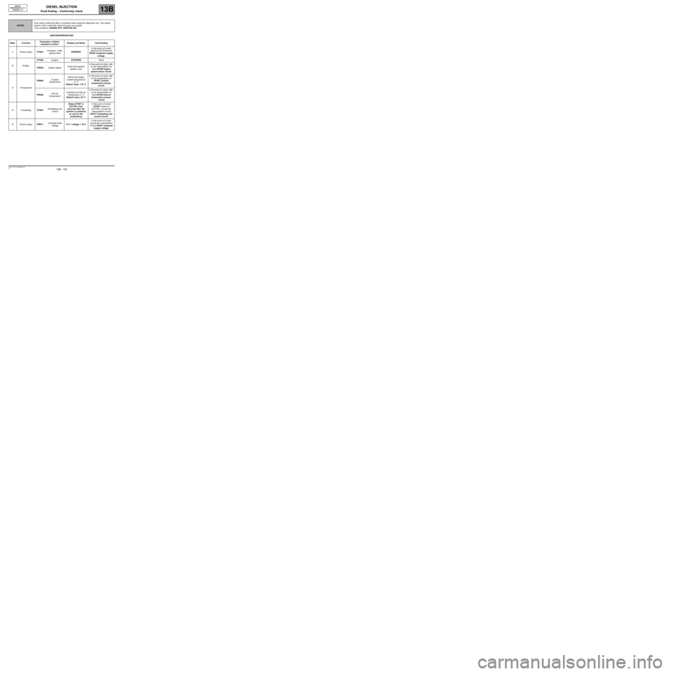
IGNITION/PREHEATING
NOTESOnly check conformity after a complete check using the diagnostic tool. The values
shown in this conformity check are given as a guide.
Test conditions: ENGINE OFF, IGNITION ON.
Order FunctionParameter or Status
checked or ActionDisplay and Notes Fault finding
1Power supplyET001:Computer + after
ignition feedPRESENTIn the event of a fault,
perform fault finding for
DF047 Computer supply
voltage.
2EngineET038:EngineSTOPPEDNone
PR055:Engine speedGives the engine's
speed in rpmIn the event of a fault, refer
to the interpretation for
fault DF005 Engine
speed sensor circuit.
3TemperaturePR064:Coolant
temperatureShows the engine
coolant temperature
in ˚C
Default value: 119 ˚CIn the event of a fault, refer
to the interpretation of
DF001 Coolant
temperature sensor
circuit.
PR059:Inlet air
temperatureIndicates the inlet air
temperature in ˚C
Default value: 20 ˚CIn the event of a fault, refer
to the interpretation of
fault DF039 Inlet air
temperature sensor
circuit
4PreheatingET007:Preheating unit
controlStatus ET007 is
ACTIVE a few
seconds after the
ignition is switched
on and for the
postheatingIn the event of a fault
(ET007 locked on
ACTIVE), consult the
interpretation of fault
DF017 Preheating unit
control circuit.
5Power supplyPR071:Computer feed
voltage9 V < voltage < 16 VIn the event of a fault,
consult the interpretation
of fault DF047 computer
supply voltage.
Page 143 of 273
DIESEL INJECTION
Fault finding – Conformity check13B
13B - 143V3 MR-372-J84-13B250$450.mif
EDC16
PROGRAM NO.: C1
Vdiag No.: 51
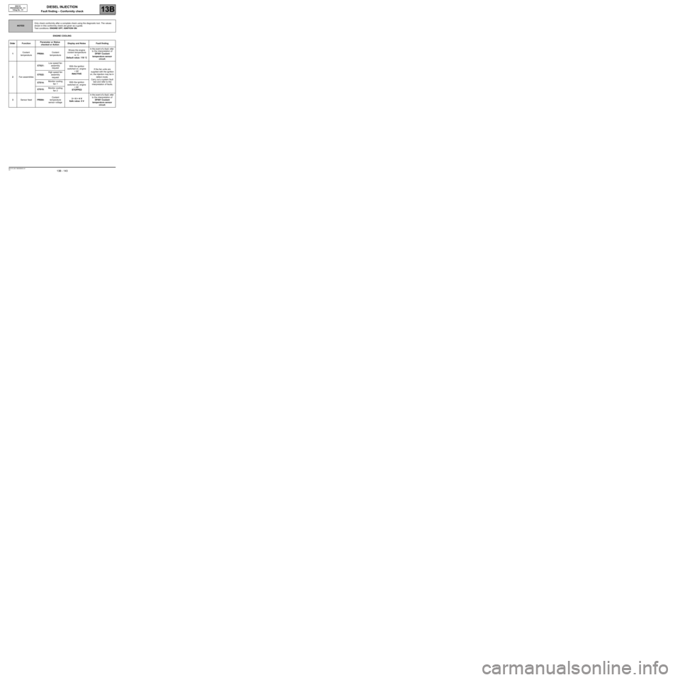
ENGINE COOLING
NOTESOnly check conformity after a complete check using the diagnostic tool. The values
shown in this conformity check are given as a guide.
Test conditions: ENGINE OFF, IGNITION ON.
Order FunctionParameter or Status
checked or ActionDisplay and Notes Fault finding
1Coolant
temperaturePR064:Coolant
temperatureShows the engine
coolant temperature
in ˚C
Default value: 119 ˚CIn the event of a fault, refer
to the interpretation of
DF001 Coolant
temperature sensor
circuit.
2Fan assembliesET021:Low speed fan
assembly
requestWith the ignition
switched on, engine
< 80˚
INACTIVEIf the fan units are
supplied with the ignition
on, the injection may be in
defect mode.
Carry out a system fault
test and refer to the
interpretation of faults. ET022:High speed fan
assembly
request
ET014:Monitor cooling
fan 1With the ignition
switched on, engine
< 80˚
STOPPED ET015:Monitor cooling
fan 2
3Sensor feedPR084:Coolant
temperature
sensor voltage3 < X < 4 V
Safe value: 5 VIn the event of a fault, refer
to the interpretation of
DF001 Coolant
temperature sensor
circuit.
Page 144 of 273
DIESEL INJECTION
Fault finding – Conformity check13B
13B - 144V3 MR-372-J84-13B250$450.mif
EDC16
PROGRAM NO.: C1
Vdiag No.: 51
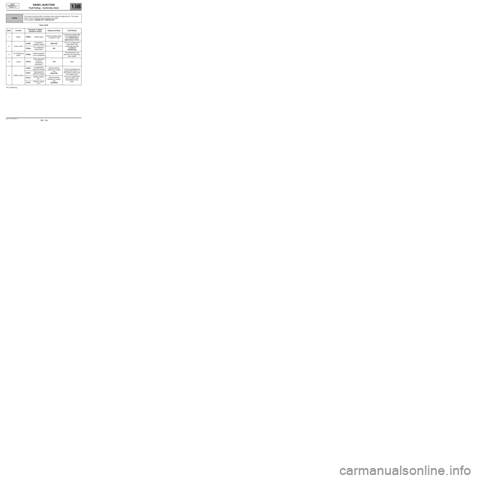
COLD LOOP
*Air Conditioning
NOTESOnly check conformity after a complete check using the diagnostic tool. The values
shown in this conformity check are given as a guide.
Test conditions: ENGINE OFF, IGNITION ON.
Order FunctionParameter or Status
checked or ActionDisplay and Notes Fault finding
1EnginePR055:Engine speedGives the engine speed
of rotation in rpmIn the event of a fault, refer
to the interpretation for
fault DF005 Engine
speed sensor circuit.
2Driver controlET088:Compressor
actuation requestINACTIVEIf the air conditioning is
authorised or the
compressor actuated
see 62A air
conditioning. ET004:Air conditioning
authorisationNO
3Air conditioning
speedPR053:Speed requested
by air conditioningThis parameter is only
valid when the engine has
been started
4OutputPR125:Power absorbed
by the air
conditioning
compressor*0 WNone
5Engine coolingET022:Low speed fan
assembly requestWith the ignition
switched on, engine
< 80˚
INACTIVEIf the fan assemblies are
supplied with ignition on,
the injection system may
be in defect mode.
Carry out a system fault
test and refer to the
interpretation of any
faults. ET021:High speed fan
assembly request
ET014:Monitor cooling
fan 1With the ignition
switched on, engine
< 80˚
STOPPED ET015:Monitor cooling
fan 2