RENAULT SCENIC 2011 J95 / 3.G Engine And Peripherals EDC16 Workshop Manual
Manufacturer: RENAULT, Model Year: 2011, Model line: SCENIC, Model: RENAULT SCENIC 2011 J95 / 3.GPages: 365, PDF Size: 2.11 MB
Page 321 of 365
13B-321
MR-372-J84-13B200$828.mif
V13
DIESEL INJECTION
Fault finding – Fault Finding Chart
EDC16
Program No.: C1
Vdiag no.: 18, 1C, 20,
50, 58, 5C
13B
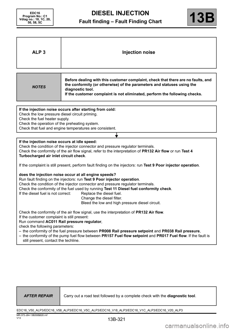
ALP 3 Injection noise
NOTESBefore dealing with this customer complaint, check that there are no faults, and
the conformity (or otherwise) of the parameters and statuses using the
diagnostic tool.
If the customer complaint is not eliminated, perform the following checks.
If the injection noise occurs after starting from cold:
Check the low pressure diesel circuit priming.
Check the fuel heater supply.
Check the operation of the preheating system.
Check that fuel and engine temperatures are consistent.
If the injection noise occurs at idle speed:
Check the condition of the injector connector and pressure regulator terminals.
Check the conformity of the air flow signal, refer to the interpretation of PR132 Air flow or run Test 4
Turbocharged air inlet circuit check.
If the complaint is still present, perform fault finding on the injectors: run Test 9 Poor injector operation.
does the injection noise occur at all engine speeds?
Run fault finding on the injectors: run Test 9 Poor injector operation.
Check the condition of the injector connector and pressure regulator terminals.
Check the conformity of the fuel used by running Test 11 Diesel fuel conformity check.
If the diesel fuel is not correct: Replace the diesel fuel.
Change the diesel filter.
Bleed the low and high pressure diesel circuit.
Check the conformity of the air flow signal, use the interpretation of PR132 Air flow.
If the customer complaint is still present:
Run command AC011 Rail pressure regulator,
check the following parameters:
– the conformity of the fuel pressure between PR008 Rail pressure setpoint and PR038 Rail pressure,
– the conformity of the pump fuel flow between PR157 Fuel flow setpoint and PR017 Fuel flow. If the fault is
still present, contact the techline.
AFTER REPAIRCarry out a road test followed by a complete check with the diagnostic tool.
EDC16_V50_ALP3/EDC16_V58_ALP3/EDC16_V5C_ALP3/EDC16_V18_ALP3/EDC16_V1C_ALP3/EDC16_V20_ALP3
Page 322 of 365
13B-322
MR-372-J84-13B200$828.mif
V13
EDC16
Program No.: C1
Vdiag no.: 18, 1C, 20,
50, 58, 5CDIESEL INJECTION
Fault finding – Fault Finding Chart13B
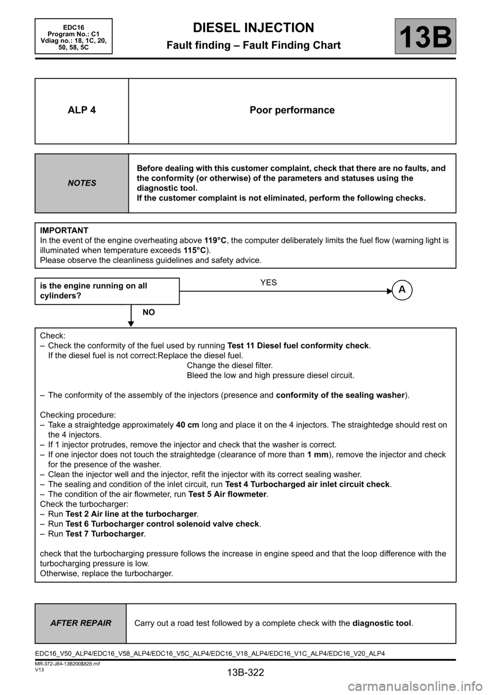
ALP 4 Poor performance
NOTESBefore dealing with this customer complaint, check that there are no faults, and
the conformity (or otherwise) of the parameters and statuses using the
diagnostic tool.
If the customer complaint is not eliminated, perform the following checks.
IMPORTANT
In the event of the engine overheating above 119°C, the computer deliberately limits the fuel flow (warning light is
illuminated when temperature exceeds 115 ° C).
Please observe the cleanliness guidelines and safety advice.
is the engine running on all
cylinders?
NO
Check:
– Check the conformity of the fuel used by running Test 11 Diesel fuel conformity check.
If the diesel fuel is not correct:Replace the diesel fuel.
Change the diesel filter.
Bleed the low and high pressure diesel circuit.
– The conformity of the assembly of the injectors (presence and conformity of the sealing washer).
Checking procedure:
– Take a straightedge approximately 40 cm long and place it on the 4 injectors. The straightedge should rest on
the 4 injectors.
– If 1 injector protrudes, remove the injector and check that the washer is correct.
– If one injector does not touch the straightedge (clearance of more than 1 mm), remove the injector and check
for the presence of the washer.
– Clean the injector well and the injector, refit the injector with its correct sealing washer.
– The sealing and condition of the inlet circuit, run Test 4 Turbocharged air inlet circuit check.
– The condition of the air flowmeter, run Test 5 Air flowmeter.
Check the turbocharger:
–Run Test 2 Air line at the turbocharger.
–Run Test 6 Turbocharger control solenoid valve check.
–Run Test 7 Turbocharger.
check that the turbocharging pressure follows the increase in engine speed and that the loop difference with the
turbocharging pressure is low.
Otherwise, replace the turbocharger.
YES
AFTER REPAIRCarry out a road test followed by a complete check with the diagnostic tool.
EDC16_V50_ALP4/EDC16_V58_ALP4/EDC16_V5C_ALP4/EDC16_V18_ALP4/EDC16_V1C_ALP4/EDC16_V20_ALP4
Page 323 of 365
13B-323
MR-372-J84-13B200$828.mif
V13
DIESEL INJECTION
Fault finding – Fault Finding Chart
EDC16
Program No.: C1
Vdiag no.: 18, 1C, 20,
50, 58, 5C
13B
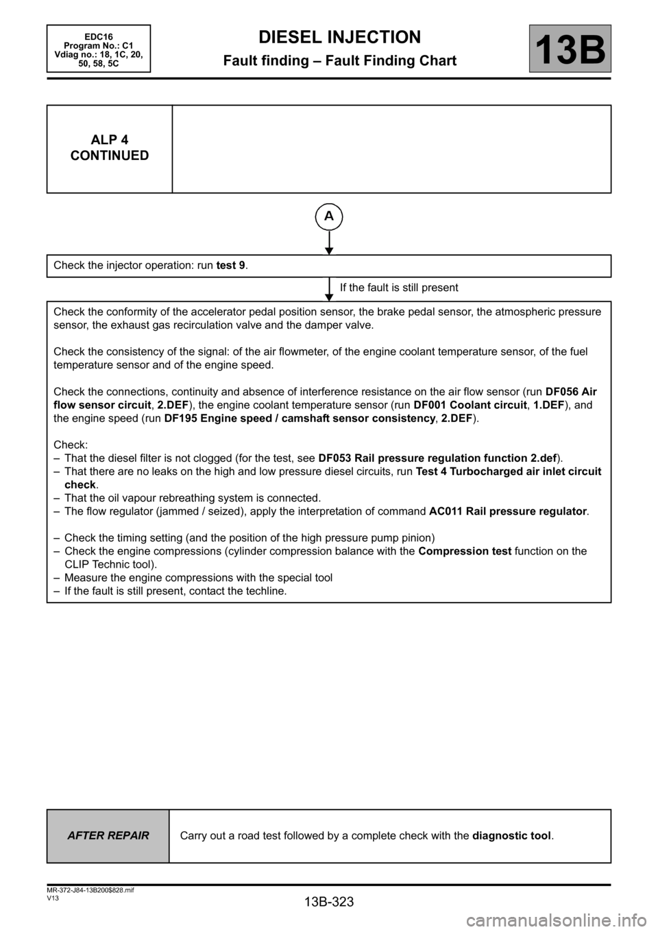
ALP 4
CONTINUED
Check the injector operation: run test 9.
If the fault is still present
Check the conformity of the accelerator pedal position sensor, the brake pedal sensor, the atmospheric pressure
sensor, the exhaust gas recirculation valve and the damper valve.
Check the consistency of the signal: of the air flowmeter, of the engine coolant temperature sensor, of the fuel
temperature sensor and of the engine speed.
Check the connections, continuity and absence of interference resistance on the air flow sensor (run DF056 Air
flow sensor circuit, 2.DEF), the engine coolant temperature sensor (run DF001 Coolant circuit, 1.DEF), and
the engine speed (run DF195 Engine speed / camshaft sensor consistency, 2.DEF).
Check:
– That the diesel filter is not clogged (for the test, see DF053 Rail pressure regulation function 2.def).
– That there are no leaks on the high and low pressure diesel circuits, run Test 4 Turbocharged air inlet circuit
check.
– That the oil vapour rebreathing system is connected.
– The flow regulator (jammed / seized), apply the interpretation of command AC011 Rail pressure regulator.
– Check the timing setting (and the position of the high pressure pump pinion)
– Check the engine compressions (cylinder compression balance with the Compression test function on the
CLIP Technic tool).
– Measure the engine compressions with the special tool
– If the fault is still present, contact the techline.
AFTER REPAIRCarry out a road test followed by a complete check with the diagnostic tool.
Page 324 of 365
13B-324
MR-372-J84-13B200$828.mif
V13
DIESEL INJECTION
Fault finding – Fault Finding Chart
EDC16
Program No.: C1
Vdiag no.: 18, 1C, 20,
50, 58, 5C
13B
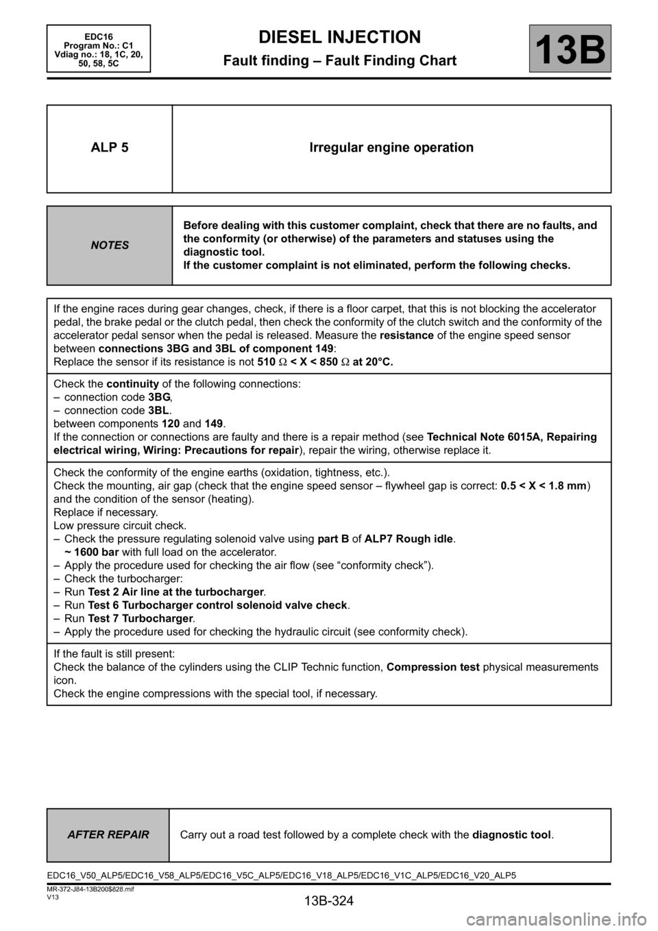
ALP 5 Irregular engine operation
NOTESBefore dealing with this customer complaint, check that there are no faults, and
the conformity (or otherwise) of the parameters and statuses using the
diagnostic tool.
If the customer complaint is not eliminated, perform the following checks.
If the engine races during gear changes, check, if there is a floor carpet, that this is not blocking the accelerator
pedal, the brake pedal or the clutch pedal, then check the conformity of the clutch switch and the conformity of the
accelerator pedal sensor when the pedal is released. Measure the resistance of the engine speed sensor
between connections 3BG and 3BL of component 149:
Replace the sensor if its resistance is not 510 Ω < X < 850 Ω at 20°C.
Check the continuity of the following connections:
– connection code 3BG,
– connection code 3BL.
between components 120 and 149.
If the connection or connections are faulty and there is a repair method (see Technical Note 6015A, Repairing
electrical wiring, Wiring: Precautions for repair), repair the wiring, otherwise replace it.
Check the conformity of the engine earths (oxidation, tightness, etc.).
Check the mounting, air gap (check that the engine speed sensor – flywheel gap is correct: 0.5 < X < 1.8 mm)
and the condition of the sensor (heating).
Replace if necessary.
Low pressure circuit check.
– Check the pressure regulating solenoid valve using part B of ALP7 Rough idle.
~ 1600 bar with full load on the accelerator.
– Apply the procedure used for checking the air flow (see “conformity check”).
– Check the turbocharger:
–Run Test 2 Air line at the turbocharger.
–Run Test 6 Turbocharger control solenoid valve check.
–Run Test 7 Turbocharger.
– Apply the procedure used for checking the hydraulic circuit (see conformity check).
If the fault is still present:
Check the balance of the cylinders using the CLIP Technic function, Compression test physical measurements
icon.
Check the engine compressions with the special tool, if necessary.
AFTER REPAIRCarry out a road test followed by a complete check with the diagnostic tool.
EDC16_V50_ALP5/EDC16_V58_ALP5/EDC16_V5C_ALP5/EDC16_V18_ALP5/EDC16_V1C_ALP5/EDC16_V20_ALP5
Page 325 of 365
13B-325
MR-372-J84-13B200$828.mif
V13
EDC16
Program No.: C1
Vdiag no.: 18, 1C, 20,
50, 58, 5CDIESEL INJECTION
Fault finding – Fault Finding Chart13B
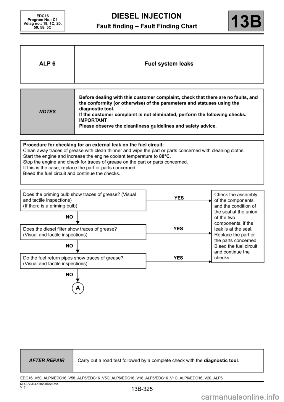
ALP 6 Fuel system leaks
NOTESBefore dealing with this customer complaint, check that there are no faults, and
the conformity (or otherwise) of the parameters and statuses using the
diagnostic tool.
If the customer complaint is not eliminated, perform the following checks.
IMPORTANT
Please observe the cleanliness guidelines and safety advice.
Procedure for checking for an external leak on the fuel circuit:
Clean away traces of grease with clean thinner and wipe the part or parts concerned with cleaning cloths.
Start the engine and increase the engine coolant temperature to 80°C.
Stop the engine and check for traces of grease on the part or parts concerned.
If this is the case, replace the part or parts concerned.
Bleed the fuel circuit and continue the checks.
Does the priming bulb show traces of grease? (Visual
and tactile inspections)
(If there is a priming bulb)
NO
Does the diesel filter show traces of grease?
(Visual and tactile inspections)
NO
Do the fuel return pipes show traces of grease?
(Visual and tactile inspections)
NO
YESCheck the assembly
of the components
and the condition of
the seal at the union
of the two
components, if the
leak is at the seal.
Replace the part or
the parts concerned.
Bleed the fuel circuit
and continue the
checks.
YES
YES
AFTER REPAIRCarry out a road test followed by a complete check with the diagnostic tool.
EDC16_V50_ALP6/EDC16_V58_ALP6/EDC16_V5C_ALP6/EDC16_V18_ALP6/EDC16_V1C_ALP6/EDC16_V20_ALP6
Page 326 of 365
13B-326
MR-372-J84-13B200$828.mif
V13
EDC16
Program No.: C1
Vdiag no.: 18, 1C, 20,
50, 58, 5CDIESEL INJECTION
Fault finding – Fault Finding Chart13B
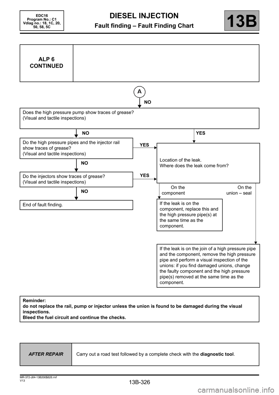
ALP 6
CONTINUED
NO
Does the high pressure pump show traces of grease?
(Visual and tactile inspections)
NO YES
Do the high pressure pipes and the injector rail
show traces of grease?
(Visual and tactile inspections)
NO
Do the injectors show traces of grease?
(Visual and tactile inspections)
NO
End of fault finding.
Reminder:
do not replace the rail, pump or injector unless the union is found to be damaged during the visual
inspections.
Bleed the fuel circuit and continue the checks.
YES
Location of the leak.
Where does the leak come from?
On the
componentOn the
union – seal
If the leak is on the
component, replace this and
the high pressure pipe(s) at
the same time as the
component.
If the leak is on the join of a high pressure pipe
and the component, remove the high pressure
pipe and perform a visual inspection of the
unions: if you find damaged unions, change
the faulty component and the high pressure
pipe(s) removed at the same time as the
component.
YES
AFTER REPAIRCarry out a road test followed by a complete check with the diagnostic tool.
Page 327 of 365
13B-327
MR-372-J84-13B200$828.mif
V13
DIESEL INJECTION
Fault finding – Fault Finding Chart
EDC16
Program No.: C1
Vdiag no.: 18, 1C, 20,
50, 58, 5C
13B
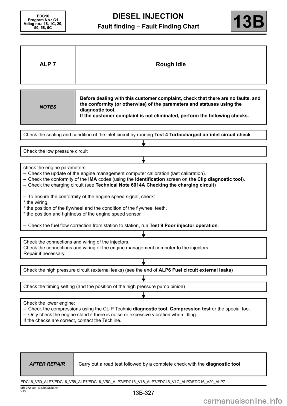
ALP 7 Rough idle
NOTESBefore dealing with this customer complaint, check that there are no faults, and
the conformity (or otherwise) of the parameters and statuses using the
diagnostic tool.
If the customer complaint is not eliminated, perform the following checks.
Check the sealing and condition of the inlet circuit by running Test 4 Turbocharged air inlet circuit check
Check the low pressure circuit
check the engine parameters:
– Check the update of the engine management computer calibration (last calibration).
– Check the conformity of the IMA codes (using the Identification screen on the Clip diagnostic tool).
– Check the charging circuit (see Technical Note 6014A Checking the charging circuit)
– To ensure the conformity of the engine speed signal, check:
* the wiring,
* the position of the flywheel and the condition of the flywheel teeth.
* the position and tightness of the engine speed sensor.
– Check the fuel flow correction from station to station, run Test 9 Poor injector operation.
Check the connections and wiring of the injectors.
Check the connections and wiring of the engine management computer to the injectors.
Repair if necessary.
Check the high pressure circuit (external leaks) (see the end of ALP6 Fuel circuit external leaks)
Check the timing setting (and the position of the high pressure pump pinion)
Check the lower engine:
– Check the compressions using the CLIP Technic diagnostic tool, Compression test or the special tool.
– Only check the engine stand if there is noise or excessive vibration when idling.
If the checks are correct, contact the Techline.
AFTER REPAIRCarry out a road test followed by a complete check with the diagnostic tool.
EDC16_V50_ALP7/EDC16_V58_ALP7/EDC16_V5C_ALP7/EDC16_V18_ALP7/EDC16_V1C_ALP7/EDC16_V20_ALP7
Page 328 of 365
13B-328
MR-372-J84-13B200$828.mif
V13
EDC16
Program No.: C1
Vdiag no.: 18, 1C, 20,
50, 58, 5CDIESEL INJECTION
Fault finding – Fault Finding Chart13B
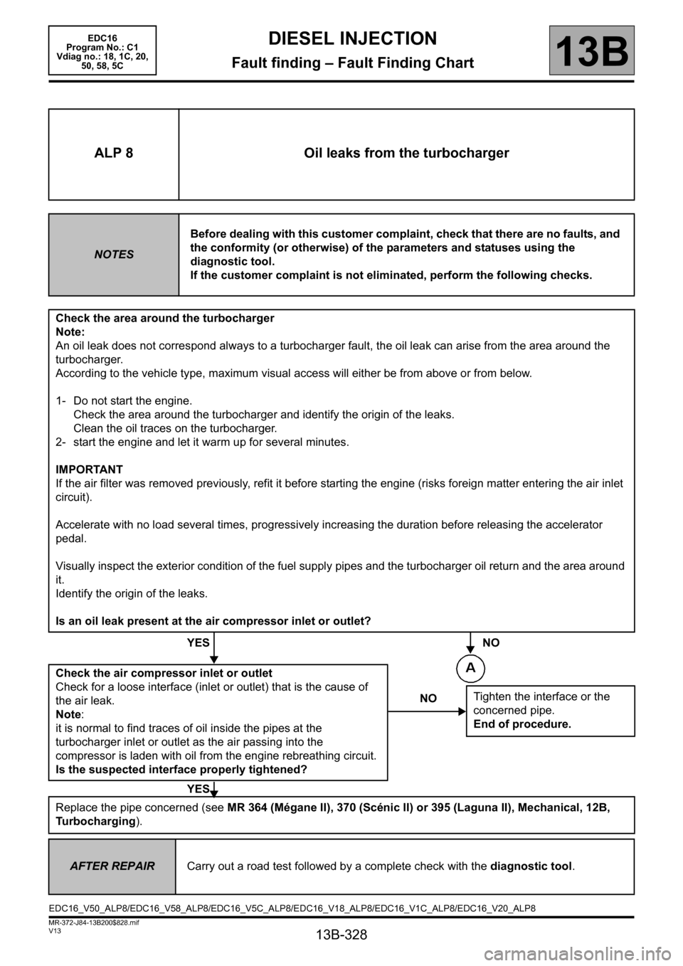
ALP 8 Oil leaks from the turbocharger
NOTESBefore dealing with this customer complaint, check that there are no faults, and
the conformity (or otherwise) of the parameters and statuses using the
diagnostic tool.
If the customer complaint is not eliminated, perform the following checks.
Check the area around the turbocharger
Note:
An oil leak does not correspond always to a turbocharger fault, the oil leak can arise from the area around the
turbocharger.
According to the vehicle type, maximum visual access will either be from above or from below.
1- Do not start the engine.
Check the area around the turbocharger and identify the origin of the leaks.
Clean the oil traces on the turbocharger.
2- start the engine and let it warm up for several minutes.
IMPORTANT
If the air filter was removed previously, refit it before starting the engine (risks foreign matter entering the air inlet
circuit).
Accelerate with no load several times, progressively increasing the duration before releasing the accelerator
pedal.
Visually inspect the exterior condition of the fuel supply pipes and the turbocharger oil return and the area around
it.
Identify the origin of the leaks.
Is an oil leak present at the air compressor inlet or outlet?
YES NO
Check the air compressor inlet or outlet
Check for a loose interface (inlet or outlet) that is the cause of
the air leak.
Note:
it is normal to find traces of oil inside the pipes at the
turbocharger inlet or outlet as the air passing into the
compressor is laden with oil from the engine rebreathing circuit.
Is the suspected interface properly tightened?
YES
Replace the pipe concerned (see MR 364 (Mégane II), 370 (Scénic II) or 395 (Laguna II), Mechanical, 12B,
Turbocharging).
NOTighten the interface or the
concerned pipe.
End of procedure.
AFTER REPAIRCarry out a road test followed by a complete check with the diagnostic tool.
EDC16_V50_ALP8/EDC16_V58_ALP8/EDC16_V5C_ALP8/EDC16_V18_ALP8/EDC16_V1C_ALP8/EDC16_V20_ALP8
Page 329 of 365
13B-329
MR-372-J84-13B200$828.mif
V13
EDC16
Program No.: C1
Vdiag no.: 18, 1C, 20,
50, 58, 5CDIESEL INJECTION
Fault finding – Fault Finding Chart13B
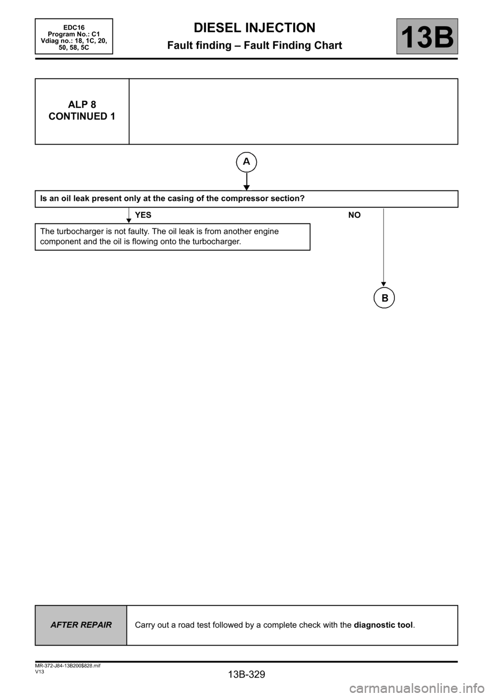
ALP 8
CONTINUED 1
Is an oil leak present only at the casing of the compressor section?
YES NO
The turbocharger is not faulty. The oil leak is from another engine
component and the oil is flowing onto the turbocharger.
AFTER REPAIRCarry out a road test followed by a complete check with the diagnostic tool.
Page 330 of 365
13B-330
MR-372-J84-13B200$828.mif
V13
EDC16
Program No.: C1
Vdiag no.: 18, 1C, 20,
50, 58, 5CDIESEL INJECTION
Fault finding – Fault Finding Chart13B
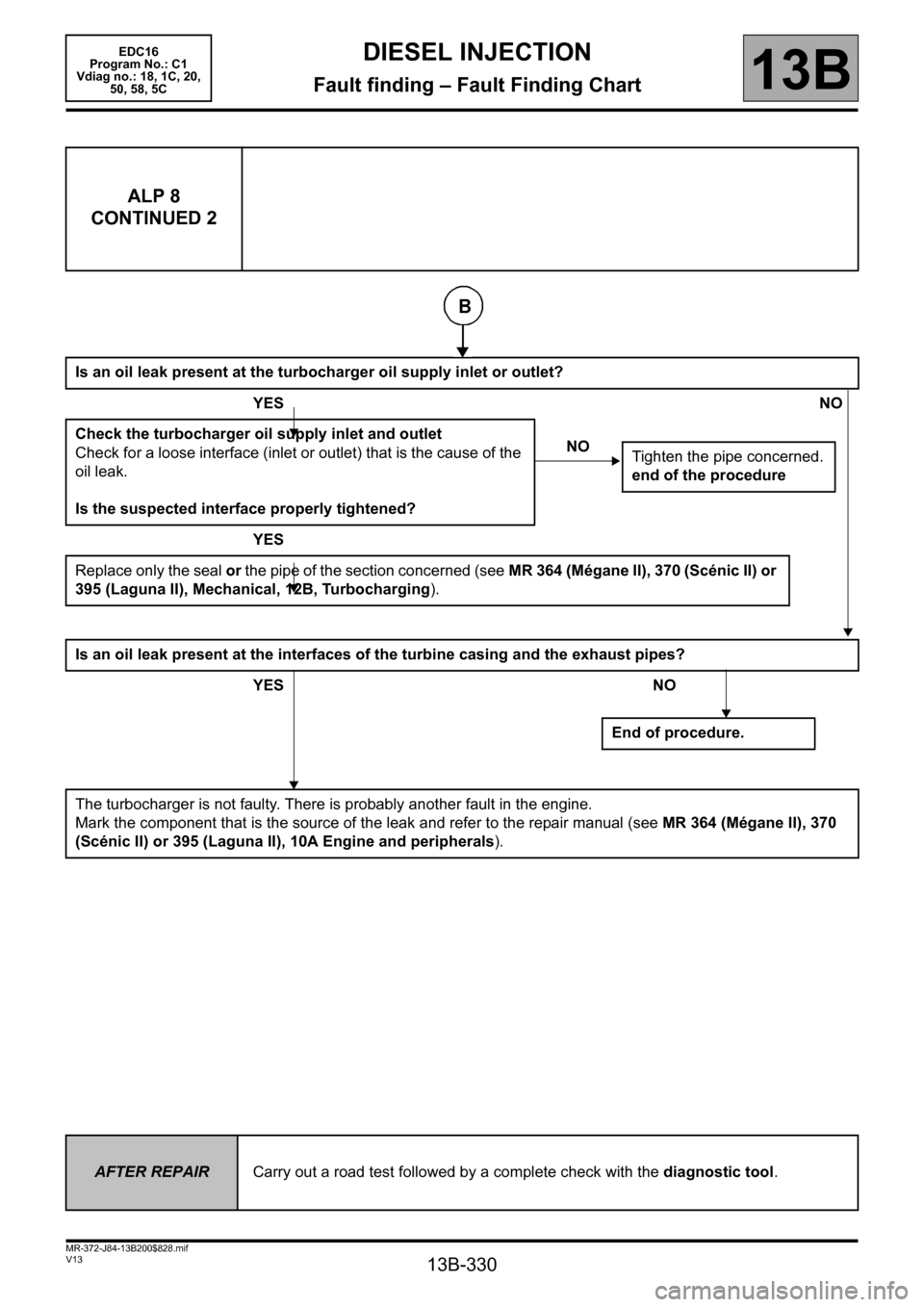
ALP 8
CONTINUED 2
Is an oil leak present at the turbocharger oil supply inlet or outlet?
YESNO
Check the turbocharger oil supply inlet and outlet
Check for a loose interface (inlet or outlet) that is the cause of the
oil leak.
Is the suspected interface properly tightened?
YES
Replace only the seal or the pipe of the section concerned (see MR 364 (Mégane II), 370 (Scénic II) or
395 (Laguna II), Mechanical, 12B, Turbocharging).
Is an oil leak present at the interfaces of the turbine casing and the exhaust pipes?
YES NO
The turbocharger is not faulty. There is probably another fault in the engine.
Mark the component that is the source of the leak and refer to the repair manual (see MR 364 (Mégane II), 370
(Scénic II) or 395 (Laguna II), 10A Engine and peripherals).
NO
Tighten the pipe concerned.
end of the procedure
End of procedure.
AFTER REPAIRCarry out a road test followed by a complete check with the diagnostic tool.